EP4157617B1 - Verfahren zur herstellung eines holmgurts für ein windturbinenschaufelteil - Google Patents
Verfahren zur herstellung eines holmgurts für ein windturbinenschaufelteil Download PDFInfo
- Publication number
- EP4157617B1 EP4157617B1 EP20728708.7A EP20728708A EP4157617B1 EP 4157617 B1 EP4157617 B1 EP 4157617B1 EP 20728708 A EP20728708 A EP 20728708A EP 4157617 B1 EP4157617 B1 EP 4157617B1
- Authority
- EP
- European Patent Office
- Prior art keywords
- stack
- precured
- elements
- mould
- interlayer
- Prior art date
- Legal status (The legal status is an assumption and is not a legal conclusion. Google has not performed a legal analysis and makes no representation as to the accuracy of the status listed.)
- Active
Links
Images




Classifications
-
- B—PERFORMING OPERATIONS; TRANSPORTING
- B29—WORKING OF PLASTICS; WORKING OF SUBSTANCES IN A PLASTIC STATE IN GENERAL
- B29C—SHAPING OR JOINING OF PLASTICS; SHAPING OF MATERIAL IN A PLASTIC STATE, NOT OTHERWISE PROVIDED FOR; AFTER-TREATMENT OF THE SHAPED PRODUCTS, e.g. REPAIRING
- B29C33/00—Moulds or cores; Details thereof or accessories therefor
- B29C33/56—Coatings, e.g. enameled or galvanised; Releasing, lubricating or separating agents
- B29C33/58—Applying the releasing agents
-
- B—PERFORMING OPERATIONS; TRANSPORTING
- B29—WORKING OF PLASTICS; WORKING OF SUBSTANCES IN A PLASTIC STATE IN GENERAL
- B29C—SHAPING OR JOINING OF PLASTICS; SHAPING OF MATERIAL IN A PLASTIC STATE, NOT OTHERWISE PROVIDED FOR; AFTER-TREATMENT OF THE SHAPED PRODUCTS, e.g. REPAIRING
- B29C70/00—Shaping composites, i.e. plastics material comprising reinforcements, fillers or preformed parts, e.g. inserts
- B29C70/04—Shaping composites, i.e. plastics material comprising reinforcements, fillers or preformed parts, e.g. inserts comprising reinforcements only, e.g. self-reinforcing plastics
- B29C70/06—Fibrous reinforcements only
-
- B—PERFORMING OPERATIONS; TRANSPORTING
- B29—WORKING OF PLASTICS; WORKING OF SUBSTANCES IN A PLASTIC STATE IN GENERAL
- B29C—SHAPING OR JOINING OF PLASTICS; SHAPING OF MATERIAL IN A PLASTIC STATE, NOT OTHERWISE PROVIDED FOR; AFTER-TREATMENT OF THE SHAPED PRODUCTS, e.g. REPAIRING
- B29C70/00—Shaping composites, i.e. plastics material comprising reinforcements, fillers or preformed parts, e.g. inserts
- B29C70/04—Shaping composites, i.e. plastics material comprising reinforcements, fillers or preformed parts, e.g. inserts comprising reinforcements only, e.g. self-reinforcing plastics
- B29C70/28—Shaping operations therefor
- B29C70/40—Shaping or impregnating by compression not applied
- B29C70/42—Shaping or impregnating by compression not applied for producing articles of definite length, i.e. discrete articles
- B29C70/44—Shaping or impregnating by compression not applied for producing articles of definite length, i.e. discrete articles using isostatic pressure, e.g. pressure difference-moulding, vacuum bag-moulding, autoclave-moulding or expanding rubber-moulding
- B29C70/443—Shaping or impregnating by compression not applied for producing articles of definite length, i.e. discrete articles using isostatic pressure, e.g. pressure difference-moulding, vacuum bag-moulding, autoclave-moulding or expanding rubber-moulding and impregnating by vacuum or injection
-
- B—PERFORMING OPERATIONS; TRANSPORTING
- B29—WORKING OF PLASTICS; WORKING OF SUBSTANCES IN A PLASTIC STATE IN GENERAL
- B29C—SHAPING OR JOINING OF PLASTICS; SHAPING OF MATERIAL IN A PLASTIC STATE, NOT OTHERWISE PROVIDED FOR; AFTER-TREATMENT OF THE SHAPED PRODUCTS, e.g. REPAIRING
- B29C70/00—Shaping composites, i.e. plastics material comprising reinforcements, fillers or preformed parts, e.g. inserts
- B29C70/04—Shaping composites, i.e. plastics material comprising reinforcements, fillers or preformed parts, e.g. inserts comprising reinforcements only, e.g. self-reinforcing plastics
- B29C70/28—Shaping operations therefor
- B29C70/40—Shaping or impregnating by compression not applied
- B29C70/42—Shaping or impregnating by compression not applied for producing articles of definite length, i.e. discrete articles
- B29C70/46—Shaping or impregnating by compression not applied for producing articles of definite length, i.e. discrete articles using matched moulds, e.g. for deforming sheet moulding compounds [SMC] or prepregs
- B29C70/48—Shaping or impregnating by compression not applied for producing articles of definite length, i.e. discrete articles using matched moulds, e.g. for deforming sheet moulding compounds [SMC] or prepregs and impregnating the reinforcements in the closed mould, e.g. resin transfer moulding [RTM], e.g. by vacuum
-
- B—PERFORMING OPERATIONS; TRANSPORTING
- B29—WORKING OF PLASTICS; WORKING OF SUBSTANCES IN A PLASTIC STATE IN GENERAL
- B29C—SHAPING OR JOINING OF PLASTICS; SHAPING OF MATERIAL IN A PLASTIC STATE, NOT OTHERWISE PROVIDED FOR; AFTER-TREATMENT OF THE SHAPED PRODUCTS, e.g. REPAIRING
- B29C70/00—Shaping composites, i.e. plastics material comprising reinforcements, fillers or preformed parts, e.g. inserts
- B29C70/68—Shaping composites, i.e. plastics material comprising reinforcements, fillers or preformed parts, e.g. inserts by incorporating or moulding on preformed parts, e.g. inserts or layers, e.g. foam blocks
- B29C70/86—Incorporated in coherent impregnated reinforcing layers, e.g. by winding
-
- B—PERFORMING OPERATIONS; TRANSPORTING
- B29—WORKING OF PLASTICS; WORKING OF SUBSTANCES IN A PLASTIC STATE IN GENERAL
- B29D—PRODUCING PARTICULAR ARTICLES FROM PLASTICS OR FROM SUBSTANCES IN A PLASTIC STATE
- B29D99/00—Subject matter not provided for in other groups of this subclass
- B29D99/0025—Producing blades or the like, e.g. blades for turbines, propellers, or wings
- B29D99/0028—Producing blades or the like, e.g. blades for turbines, propellers, or wings hollow blades
-
- B—PERFORMING OPERATIONS; TRANSPORTING
- B29—WORKING OF PLASTICS; WORKING OF SUBSTANCES IN A PLASTIC STATE IN GENERAL
- B29C—SHAPING OR JOINING OF PLASTICS; SHAPING OF MATERIAL IN A PLASTIC STATE, NOT OTHERWISE PROVIDED FOR; AFTER-TREATMENT OF THE SHAPED PRODUCTS, e.g. REPAIRING
- B29C70/00—Shaping composites, i.e. plastics material comprising reinforcements, fillers or preformed parts, e.g. inserts
- B29C70/04—Shaping composites, i.e. plastics material comprising reinforcements, fillers or preformed parts, e.g. inserts comprising reinforcements only, e.g. self-reinforcing plastics
- B29C70/28—Shaping operations therefor
- B29C70/40—Shaping or impregnating by compression not applied
- B29C70/50—Shaping or impregnating by compression not applied for producing articles of indefinite length, e.g. prepregs, sheet moulding compounds [SMC] or cross moulding compounds [XMC]
- B29C70/52—Pultrusion, i.e. forming and compressing by continuously pulling through a die
-
- B—PERFORMING OPERATIONS; TRANSPORTING
- B29—WORKING OF PLASTICS; WORKING OF SUBSTANCES IN A PLASTIC STATE IN GENERAL
- B29K—INDEXING SCHEME ASSOCIATED WITH SUBCLASSES B29B, B29C OR B29D, RELATING TO MOULDING MATERIALS OR TO MATERIALS FOR MOULDS, REINFORCEMENTS, FILLERS OR PREFORMED PARTS, e.g. INSERTS
- B29K2031/00—Use of polyvinylesters or derivatives thereof as moulding material
-
- B—PERFORMING OPERATIONS; TRANSPORTING
- B29—WORKING OF PLASTICS; WORKING OF SUBSTANCES IN A PLASTIC STATE IN GENERAL
- B29K—INDEXING SCHEME ASSOCIATED WITH SUBCLASSES B29B, B29C OR B29D, RELATING TO MOULDING MATERIALS OR TO MATERIALS FOR MOULDS, REINFORCEMENTS, FILLERS OR PREFORMED PARTS, e.g. INSERTS
- B29K2063/00—Use of EP, i.e. epoxy resins or derivatives thereof, as moulding material
-
- B—PERFORMING OPERATIONS; TRANSPORTING
- B29—WORKING OF PLASTICS; WORKING OF SUBSTANCES IN A PLASTIC STATE IN GENERAL
- B29K—INDEXING SCHEME ASSOCIATED WITH SUBCLASSES B29B, B29C OR B29D, RELATING TO MOULDING MATERIALS OR TO MATERIALS FOR MOULDS, REINFORCEMENTS, FILLERS OR PREFORMED PARTS, e.g. INSERTS
- B29K2067/00—Use of polyesters or derivatives thereof, as moulding material
-
- B—PERFORMING OPERATIONS; TRANSPORTING
- B29—WORKING OF PLASTICS; WORKING OF SUBSTANCES IN A PLASTIC STATE IN GENERAL
- B29K—INDEXING SCHEME ASSOCIATED WITH SUBCLASSES B29B, B29C OR B29D, RELATING TO MOULDING MATERIALS OR TO MATERIALS FOR MOULDS, REINFORCEMENTS, FILLERS OR PREFORMED PARTS, e.g. INSERTS
- B29K2307/00—Use of elements other than metals as reinforcement
- B29K2307/04—Carbon
-
- B—PERFORMING OPERATIONS; TRANSPORTING
- B29—WORKING OF PLASTICS; WORKING OF SUBSTANCES IN A PLASTIC STATE IN GENERAL
- B29L—INDEXING SCHEME ASSOCIATED WITH SUBCLASS B29C, RELATING TO PARTICULAR ARTICLES
- B29L2031/00—Other particular articles
- B29L2031/08—Blades for rotors, stators, fans, turbines or the like, e.g. screw propellers
-
- Y—GENERAL TAGGING OF NEW TECHNOLOGICAL DEVELOPMENTS; GENERAL TAGGING OF CROSS-SECTIONAL TECHNOLOGIES SPANNING OVER SEVERAL SECTIONS OF THE IPC; TECHNICAL SUBJECTS COVERED BY FORMER USPC CROSS-REFERENCE ART COLLECTIONS [XRACs] AND DIGESTS
- Y02—TECHNOLOGIES OR APPLICATIONS FOR MITIGATION OR ADAPTATION AGAINST CLIMATE CHANGE
- Y02E—REDUCTION OF GREENHOUSE GAS [GHG] EMISSIONS, RELATED TO ENERGY GENERATION, TRANSMISSION OR DISTRIBUTION
- Y02E10/00—Energy generation through renewable energy sources
- Y02E10/70—Wind energy
- Y02E10/72—Wind turbines with rotation axis in wind direction
-
- Y—GENERAL TAGGING OF NEW TECHNOLOGICAL DEVELOPMENTS; GENERAL TAGGING OF CROSS-SECTIONAL TECHNOLOGIES SPANNING OVER SEVERAL SECTIONS OF THE IPC; TECHNICAL SUBJECTS COVERED BY FORMER USPC CROSS-REFERENCE ART COLLECTIONS [XRACs] AND DIGESTS
- Y02—TECHNOLOGIES OR APPLICATIONS FOR MITIGATION OR ADAPTATION AGAINST CLIMATE CHANGE
- Y02P—CLIMATE CHANGE MITIGATION TECHNOLOGIES IN THE PRODUCTION OR PROCESSING OF GOODS
- Y02P70/00—Climate change mitigation technologies in the production process for final industrial or consumer products
- Y02P70/50—Manufacturing or production processes characterised by the final manufactured product
Definitions
- the present invention relates to manufacturing of spar cap for a wind turbine blade.
- Wind power is a clean and environmentally friendly source of energy.
- Wind turbines usually comprise a tower, generator, gearbox, nacelle, and one or more rotor blades.
- the wind turbine blades capture kinetic energy of wind using known airfoil principles.
- Modern wind turbines may have rotor blades that exceed 90 meters in length.
- Wind turbine blades are usually manufactured by forming two shell parts or shell halves from layers of woven fabric or fibre and resin. Spar caps or main laminates are placed or integrated in the shell halves and may be combined with shear webs or spar beams to form structural support. Spar caps or main laminates may be joined to, or integrated within, the inside of the halves of the shell.
- layers of dry fibre such as fibre mats
- these layers will constitute the outer skin of the shell part.
- additional layers forming part of the spar cap one or more precured elements can be added, forming a further part of the spar cap blade shell part.
- Spar caps are advantageously provided using this method. Adding the additional layers and the precured elements onto the outer skin fibre layers is tedious, and often the fibre layers get displaced or wrinkled or misplaced, thereby reducing the dimensional tolerances and the quality of the spar and the wind turbine blade shell and thereby probably also the complete blade shell.
- WO 2016/015736 A1 discloses a method and system for manufacture of a wind turbine blade by providing a plurality of precured elongate elements of a fibre reinforced resin composite material, stacking the plurality of precured elements with an interlayers of an elongate non-cured fibre material, thereby forming a stack of precured elements and interlayers and infusing resin into the stack of precured elements and interlayers in the mould.
- the present invention provides a method of manufacturing as defined in claim 1 as well as a system for manufacturing as defined in claim 15, eliminating or reducing the drawbacks of known methods.
- the present invention provides a method of manufacturing a spar cap for a wind turbine blade part, comprising the steps of:
- the present invention provides for a spar cap having dimensions with close tolerances as the spar cap is moulded in a spar cap mould maintaining the cured elements and the interlayer(s) in the desired position and preventing displacement thereof.
- the plurality of precured elements can be stacked in a single row or in two or more rows of precured elements arranged laterally adjacent each other
- the precured elements comprise carbon fibres and/or glass fibres
- the resin of resin composite material of the precured elements is epoxy resin, vinyl ester resin or polyester resin
- the resin infused into the stack of precured elements and interlayer(s) is of the same type as the resin of the precured elements.
- the resin infused into the stack of precured elements and interlayer(s) can also be of a type different from the resin of the precured elements.
- the plurality of precured elements are pultruded elements.
- the fibres of the fibres material of the interlayer(s) can comprise glass fibres and/or carbon fibres.
- the step of stacking of the precured elements to form a stack of precured elements and interlayer(s) comprises:
- the step of moving the stack of precured elements and interlayer(s) to a spar cap mould comprises:
- the step of arranging the stack of precured elements and Interlayer(s) in the cavity of the spar cap mould comprises:
- the step of arranging the stack of precured elements and interlayer(s) in the cavity of the spar cap mould comprises:
- the stack can be gently and precisely lowered down onto the surface of the bottom.
- All the clamping devices can be removed from the stack after the stack has been arranged on the support members.
- the clamping devices can be removed gradually from the stack simultaneously with the removal of the support members or gradually prior to the gradual removal of the support members.
- the support members extend transversely of the elongate spar cap mould and are supported by upper faces of side walls of the mould.
- the support members can be cylindrical members.
- the method of the present invention comprises coating the surfaces of the mould bottom and the side walls of the mould cavity by a slip coating, such as a peel ply, prior to arranging the stack of precured elements and interlayer(s) in the cavity of the spar cap mould.
- a slip coating such as a peel ply
- the step of infusing resin into the stack of precured elements and interlayer(s) in the mould comprises: coating the upper surface of the stack of precured elements and interlayers with a peel coating, such as peel ply, and cover the cavity of the spar cap mould with a vacuum bag and infuse the resin by vacuum assisted resin transfer moulding (VARTM).
- VARTM vacuum assisted resin transfer moulding
- An embodiment of the present invention of the can comprise carrying out an inspection of the cured stack of precured elements and interlayer(s) after the cured stack has been removed from the spar cap mould, conduct any required repairs of the cured stack and send the stack to shell part mould or a storage.
- the cured stack of elements and interlayer(s), i.e. the cap can have a width in the range 30-800 mm, a thickness or height in the range of 10-200 mm and a length in the range 10-200 m
- the cured stack of cured elements and interlayer(s), i.e the spar cap, is placed on the desired place of one or more fibres layers arranged in the shell part mould and additional shell materials and consumables are added, where after the shell part is infused, such as by VARTM.
- a second aspect of the present invention relates to a wind turbine blade being provided with a spar cap manufactured by the method according to the present invention.
- a third aspect of the present invention related to a wind turbine rotor being provided with at least one blade being provided with a spar cap manufactured by a method according to the present invention.
- a fourth aspect of the present invention relates to a wind turbine comprising a wind turbine rotor being provided with at least one blade being provided with a spar cap manufactured by a method according to the present invention.
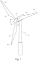
- Fig. 1 illustrates a conventional modern upwind wind turbine 2 according to the so-called "Danish concept" with a tower 4, a nacelle 6 and a rotor with a substantially horizontal rotor shaft.
- the rotor includes a hub 8 and three blades 10 extending radially from the hub 8, each blade having a blade root 16 nearest the hub and a blade tip 14 furthest from the hub 8.
- the invention is not limited to use in wind turbines of this type.
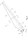
- Fig. 2 shows a schematic view of an exemplary wind turbine blade 10.
- the wind turbine blade 10 has the shape of a conventional wind turbine blade with a root end 17 and a tip end 15 and comprises a root region 30 closest to the hub, a profiled or airfoil region 34, and a transition region 32 between the root region 30 and the airfoil region 34.
- the blade 10 comprises a leading edge 18 facing the direction of rotation of the blade 10, when the blade is mounted on the hub, and a trailing edge 20 facing the opposite direction of the leading edge 18.
- the airfoil region 34 (also called the profiled region) preferably has an ideal shape with respect to generating hub rotation, whereas the root region 30 due to structural considerations has a substantially circular or elliptical cross-section, which for instance makes it easier and safer to mount the blade 10 to the hub.
- the diameter of the root region 30 may be constant along the entire root area 30.
- the transition region 32 present in the wind turbine blade 10 in this example has a transitional profile gradually changing from the circular shape of the root region 30 to the airfoil profile of the airfoil region 34.
- the chord length of the transition region 32 typically increases in an outward direction from the hub.
- the airfoil region 34 has an airfoil profile with a chord extending between the leading edge 18 and the trailing edge 20 of the blade 10.
- the wind turbine blade 10 comprises a blade shell which may for instance comprise two blade shell parts, a first blade shell part 24 and a second blade shell part 26, for instance made at least partly of fibre-reinforced polymer.
- the first blade shell part 24 may for instance be part of a pressure side or upwind blade part.
- the second blade shell part 26 may for instance be part of a suction side or downwind blade part.
- the first blade shell part 24 and the second blade shell part 26 are typically joined together, such as glued together, along bond lines or glue joints 28 extending along the trailing edge 20 and the leading edge 18 of the blade 10.
- the root ends of the blade shell parts 24, 26 have a semi-circular or semi-oval outer cross-sectional shape that, when the first and second shell parts are joined, forms the root region, such as a circular or oval root region.
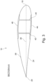
- Fig. 3 is a schematic diagram illustrating a cross-sectional view of the exemplary wind turbine blade 10, corresponding to line A-A in Fig. 2 .
- the wind turbine blade 10 comprises shear webs 40, a first spar cap 44 that is part of the pressure side 24 of the blade 10, and a second spar cap 46 that is part of the suction side 26 of the blade 10.
- the spar caps provide structural strength to the blade and typically extend along the blade in a spanwise direction. Typically, spar caps will extend over 60-95% of the blade length.
- the trailing edge 20 and leading edge 18 are also indicated in Fig. 3 .
- Fig. 4 illustrates a first step of the method according to the present invention for manufacturing a spar cap , such as the spar caps 44 and 46 in Fig.3 and where a plurality of precured elongate elements 50 of a fibre reinforced resin composite material are provided, preferably pultruded elements comprising carbon fibre.
- the precured elements 50 comprise a first main surface 51 and an opposite second main surface 52 and a first lateral face 53 and an opposite second lateral face 54 and a first end 55 and an opposite second end 56, not shown in Fig. 4 .
- the precured elements 50 are stacked with an interlayer 57 of a non-cured fibre material between the first and second main surface 51,52 of successive precured elements 50, thereby forming a loose stack 58 of precured elements 50 and interlayers 57.
- the interlayers comprise carbon and/or glass fibres.
- the loose stack 58 comprises an array of two lateral adjacent rows, each comprising four elongate precured elements 50 separated by three interlayers 57.
- the loose stack 58 has an upper stack surface 59, an opposite lower stack surface 60, a first lateral stack face 61 and an opposite second lateral stack face 62 and a first stack end 63 and an opposite second stack end 64. The first and second stack end are not shown in Fig.4 .
- a loose stack clamping device 65 surrounding a loose stack 58 is illustrated in fig. 5A .
- the loose stack 58 surrounded by the mutually spaced loose stack clamping devices 65 is moved to a spar cap mould 66 by connecting a lifting device, in the embodiment shown a lifting beam 67 with lifting ropes, to the loose stack clamping devices 65, as shown in Fig. 5B .
- the loose stack 58 is moved to the spar cap mould and arranged above the mould essentially vertically in line with the mould 66, as shown in Fig. 6A.
- Fig. 6A is a cross sectional view in reduced scale along the line C-C in Fig. 6B.
- Fig 6B is a view in enlarged scale along the line D-D in Fig. 6A .
- the loose stack 58 can be arranged in the cavity 69 of the mould by gradually bringing the lower stack surface 78 into contact with the bottom surface 71 of the mould 66 by gradually lowering the loose stack clamping devices 65 starting at the first stack end 63 and ending at the opposite second stack end 64 and simultaneously gradually removing the loose stack clamping devices starting at the clamping device closest to the first end 63 of the loose stack 58 and ending at the clamping device closest to the second end 54 of the loose stack 58.
- the loose stack can be arranged in the cavity 69 of the mould 66 by arranging a plurality of transversely extending and longitudinally mutually spaced support members in the form of cylindrical rollers 73 on the upper surfaces 74,75 of the side walls 76,77 of the mould 66. Thereafter the loose stack 58 can be lowered downwards to be supported by the plurality of longitudinally spaced rollers 73, as shown in Fig 6C and Fig. 6D . Each roller 73 supports a portion of the loose stack 58.
- the loose stack clamping devices 65 can now be removed from the loose stack.
- the lower surface 78 of the loose stack 58 is gradually brougt into contact with the surface 71 of the mould bottom of the mould cavity 69, starting at the first stack end 63 and ending at the opposite second stack end 64, by simultaneously gradually removing or displacing the rollers 73 starting from the roller closest to the first stack end 63 and ending at the support member closest to the opposite second stack end 64, as shown in Fig. 6E and Fig. 6F.
- Fig 6E and Fig. 6F disclose the situation where rollers 73 at the forward end of the loose stack 58 has been removed and the forward end of the loose stack has contacted the surface 71 of the bottom of the cavity 69 of the spar cap mould 66.
- All the clamping devices 65 can be removed from the stack 58 after the stack has been arranged on the rollers 73. Alternatively, the clamping devices 65 can be removed gradually from the stack 58 simultaneously with the removal of the rollers 73 or gradually prior to the gradual removal of the rollers 73.
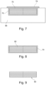
- a peel ply 70 is arranged on the upper stack surface 59 when the entire length of the lose stack 58 has been arranged in the cavity 69 of the mould 66. Thereafter, the cavity is covered with a vacuum bag 79, vacuum is provided in the mould cavity and resin supplied to the mould cavity, i.e. resin is infused by vacuum assisted resin transfer moulding (VARTM). Subsequently the resin is allowed to cure, thereby forming the spar cap 80, and the cured stack of precured elements and interlayers is removed from the mould as a spar cap 80 surrounded by peel ply 70, as shown in Fig. 8 .
- VARTM vacuum assisted resin transfer moulding
- the spar cap 80 can be inspected and required repair conducted and the spar cap 80 send to a shell part mould or a storage.
- the peel ply 70 is not removed from the spar cap 80 until the spar cap is to be used at the shell part mould.
- the spar cap is placed on the desired place of one or more fibre layers arranged in the shell part mould and additional shell materials and consumables are added, where after the shell part is infused, such as by VARTM.
Landscapes
- Engineering & Computer Science (AREA)
- Mechanical Engineering (AREA)
- Chemical & Material Sciences (AREA)
- Composite Materials (AREA)
- Wind Motors (AREA)
- Moulding By Coating Moulds (AREA)
Claims (15)
- Verfahren zur Herstellung eines Holmgurts (80) für ein Windkraftanlagenblattteil (10), das die folgenden Schritte umfasst:- Bereitstellen von mehreren vorgehärteten länglichen Elementen (50) aus einem faserverstärkten Harzverbundwerkstoff, die eine erste Hauptfläche (51) und eine zweite, entgegengesetzte Hauptfläche (53) und eine erste Seitenfläche (54) und eine zweite, entgegengesetzte Seitenfläche (63) und ein erstes Ende und ein entgegengesetztes zweites Ende (56) umfassen,- Stapeln der mehreren vorgehärteten Elemente, einer Zwischenlage (57) aus einem länglichen, nicht ausgehärteten Fasermaterial, die zwischen der ersten und der zweiten Hauptfläche aufeinanderfolgender vorgehärteter Elemente angeordnet wird, wodurch ein Stapel (58) aus vorgehärteten Elementen (50) und Zwischenlage(n) gebildet wird, wobei der Stapel eine untere Stapeloberfläche (78, 79) und eine entgegengesetzte obere Stapeloberfläche (59), eine erste Stapelseitenfläche (61, 62) und eine entgegengesetzte zweite Stapelseitenfläche (63) und ein erstes Stapelende (64) und ein entgegengesetztes zweites Stapelende (65) aufweist,- Bewegen des Stapels aus vorgehärteten Elementen und Zwischenlage(n) zu einer Holmgurtform, die einen Formboden und Formseitenwände umfasst,- Anordnen des Stapels aus vorgehärteten Elementen und Zwischenlage(n) im Hohlraum der Holmgurtform (66),- Einbringen von Harz durch Infusion in den Stapel aus vorgehärteten Elementen und Zwischenlagen in der Form,- Aushärtenlassen des Harzes zum Bilden eines ausgehärteten Stapels aus vorgehärteten Elementen und Zwischenlage(n), der einen Holmgurt bildet,- Entfernen des ausgehärteten Stapels aus vorgehärteten Elementen und Zwischenlage(n) aus der Form, d. h. Entformen des Stapels.
- Verfahren nach Anspruch 1, wobei die vorgehärteten Elemente Kohlenstofffasern und/oder Glasfasern umfassen.
- Verfahren nach einem der vorhergehenden Ansprüche, wobei das Harz des Harzverbundwerkstoffs der vorgehärteten Elemente Epoxidharz, Vinylesterharz oder Polyesterharz ist.
- Verfahren nach einem der vorhergehenden Ansprüche, wobei das in den Stapel aus vorgehärteten Elementen und Zwischenlage(n) durch Infusion eingebrachte Harz vom gleichen Typ wie das Harz der vorgehärteten Elemente ist.
- Verfahren nach einem der vorhergehenden Ansprüche, wobei die vorgehärteten Elemente bohlenförmig oder streifenförmig sind.
- Verfahren nach einem der vorhergehenden Ansprüche, wobei die mehreren vorgehärteten Elemente pultrudierte Elemente sind und/oder wobei die Fasern des Fasermaterials der Zwischenlage(n) Glasfasern und/oder Kohlenstofffasern umfassen.
- Verfahren nach einem der vorhergehenden Ansprüche, wobei der Schritt des Stapelns der vorgehärteten Elemente zum Bilden eines Stapels aus vorgehärteten Elementen und Zwischenlage(n) Folgendes umfasst:- Ausrichten wenigstens der Seitenflächen der vorgehärteten Elemente und Ausgerichtethalten dieser mithilfe von längs voneinander beabstandeten Lose-Stapel-Klemmvorrichtungen, wobei sie den Stapel aus vorgehärteten Elementen und Zwischenlage(n) vorzugsweise umgeben.
- Verfahren nach einem der vorhergehenden Ansprüche, wobei der Schritt des Bewegens des Stapels aus vorgehärteten Elementen und Zwischenlage(n) zu einer Holmgurtform Folgendes umfasst:- Verbinden einer Hebevorrichtung, wie etwa eines Hebebalkens, mit den Lose-Stapel-Klemmvorrichtungen und Bewegen des Stapels aus vorgehärteten Elementen und Zwischenlage(n) mithilfe der Hebevorrichtung zu der Form.
- Verfahren nach einem der vorhergehenden Ansprüche, wobei der Schritt des Anordnens des Stapels aus vorgehärteten Elementen und Zwischenlage(n) im Hohlraum der Holmgurtform Folgendes umfasst:- Anordnen des Stapels über dem Formhohlraum der Holmgurtform und- allmähliches Inkontaktbringen der unteren Stapeloberfläche des Stapels mit der Oberfläche des Formbodens des Formhohlraums, vorzugsweise ausgehend von dem ersten Stapelende und endend am entgegengesetzten zweiten Stapelende, und gleichzeitig allmähliches Entfernen der voneinander beabstandeten Lose-Stapel-Klemmvorrichtungen vom Stapel vor Kontakt mit dem Boden der Form, vorzugsweise ausgehend von der dem ersten Stapelende am nächsten befindlichen Lose-Stapel-Klemmvorrichtung und endend an der dem entgegengesetzten zweiten Stapelende am nächsten befindlichen Lose-Stapel-Klemmvorrichtung.
- Verfahren nach einem der vorhergehenden Ansprüche 1 bis 8, wobei das Anordnen des Stapels aus vorgehärteten Elementen und Zwischenlage(n) im Hohlraum der Holmgurtform Folgendes umfasst:- Anordnen des Stapels über dem Formhohlraum der Holmgurtform auf mehreren längs voneinander beabstandeten Stützelementen, wobei jedes Stützelement einen Stapelteil stützt, und Entfernen der Klemmvorrichtungen vom Stapel und- allmähliches Inkontaktbringen der unteren Stapeloberfläche des Stapels mit der Oberfläche des Formbodens des Formhohlraums, vorzugsweise ausgehend vom ersten Stapelende und endend am entgegengesetzten zweiten Stapelende, durch gleichzeitiges allmähliches Entfernen der Stützelemente, vorzugsweise ausgehend von dem dem ersten Stapelende am nächsten befindlichen Stützelement und endend an dem dem entgegengesetzten zweiten Stapelende am nächsten befindlichen Stützelement.
- Verfahren nach Anspruch 10, wobei die Stützelemente sich quer zur länglichen Holmgurtform erstrecken und von Oberseiten von Seitenwänden der Form getragen werden.
- Verfahren nach einem der vorhergehenden Ansprüche, umfassend das Beschichten der Oberflächen des Formbodens und der Seitenwände des Formenhohlraums mit einer Gleitbeschichtung, wie etwa einer Peel Ply-Schicht, vor Anordnen des Stapels aus vorgehärteten Elementen und Zwischenlage(n) im Hohlraum der Holmgurtform.
- Verfahren nach einem der vorhergehenden Ansprüche, wobei der Schritt des Einbringens von Harz durch Infusion in den Stapel aus vorgehärteten Elementen und Zwischenlage(n) in der Form Folgendes umfasst: Beschichten der oberen Oberfläche des Stapels aus vorgehärteten Elementen und Zwischenlagen mit einer Abziehbeschichtung, wie etwa Peel Ply, und Abdecken des Hohlraums der Holmgurtform mit einem Vakuumsack und Einbringen des Harzes durch Infusion durch vakuumunterstütztes Harzinfusionsformen (VARTM, Vacuum Assisted Resin Transfer Moulding).
- Verfahren nach einem der vorhergehenden Ansprüche, umfassend das Durchführen einer Prüfung des ausgehärteten Stapels aus vorgehärteten Elementen und Zwischenlage(n) nach dem Entfernen des ausgehärteten Stapels aus der Holmgurtform, das Durchführen erforderlicher Reparaturen des ausgehärteten Stapels und das Senden des Stapels zu Schalenteilform oder einem Lager.
- System zur Herstellung eines Holmgurts (80) für ein Windkraftanlagenblattteil (10), wobei dem System mehrere vorgehärtete längliche Elemente (50) aus einem faserverstärkten Harzverbundwerkstoff bereitgestellt werden, die eine erste Hauptfläche (51) und eine zweite, entgegengesetzte Hauptfläche (52) und eine erste Seitenfläche (53) und eine zweite, entgegengesetzte Seitenfläche (55) und ein erstes Ende (63) und ein entgegengesetztes zweites Ende (56) umfassen, und wobei die mehreren vorgehärteten Elemente mit einer Zwischenlage (57) aus einem länglichen, nicht ausgehärteten Fasermaterial, die zwischen der ersten und der zweiten Hauptfläche aufeinanderfolgender vorgehärteter Elemente (50) angeordnet wird, gestapelt werden, wodurch ein Stapel (58) aus vorgehärteten Elementen und Zwischenlage(n) gebildet wird, wobei der Stapel eine untere Stapeloberfläche (79) und eine entgegengesetzte obere Stapeloberfläche (59), eine erste Stapelseitenfläche (61) und eine entgegengesetzte zweite Stapelseitenfläche (63) und ein erstes Stapelende (64) und ein entgegengesetztes zweites Stapelende (65) aufweist,
wobei wenigstens die Seitenflächen der vorgehärteten Elemente ausgerichtet werden und mithilfe von längs voneinander beabstandeten Lose-Stapel-Klemmvorrichtungen ausgerichtet gehalten werden,wobei das System Folgendes umfasst:- eine Holmgurtform (66, 67), die einen Formboden und Formseitenwände umfasst, und- eine Hebevorrichtung, wie etwa einen Hebebalken (67, 68), die zum Bewegen des Stapels aus vorgehärteten Elementen und Zwischenlage(n) eingerichtet ist,wobei das System eingerichtet ist zum:- Verbinden der Hebevorrichtung mit den Lose-Stapel-Klemmvorrichtungen,- Bewegen des Stapels (58) aus vorgehärteten Elementen (50) und Zwischenlage(n) (57) mit der Hebevorrichtung zur Holmgurtform,- Anordnen des Stapels aus vorgehärteten Elementen und Zwischenlage(n) im Hohlraum der Holmgurtform,- Einbringen von Harz durch Infusion in den Stapel aus vorgehärteten Elementen und Zwischenlagen in der Form,- Aushärtenlassen des Harzes zum Bilden eines ausgehärteten Stapels aus vorgehärteten Elementen und Zwischenlage(n), der einen Holmgurt bildet,- Entfernen des ausgehärteten Stapels aus vorgehärteten Elementen und Zwischenlage(n) aus der Form, d. h. Entformen des Stapels,
Applications Claiming Priority (1)
| Application Number | Priority Date | Filing Date | Title |
|---|---|---|---|
| PCT/EP2020/064412 WO2021239207A1 (en) | 2020-05-25 | 2020-05-25 | Method of manufactoring a spar cap for a wind turbine blade part |
Publications (2)
| Publication Number | Publication Date |
|---|---|
| EP4157617A1 EP4157617A1 (de) | 2023-04-05 |
| EP4157617B1 true EP4157617B1 (de) | 2024-10-09 |
Family
ID=70861465
Family Applications (1)
| Application Number | Title | Priority Date | Filing Date |
|---|---|---|---|
| EP20728708.7A Active EP4157617B1 (de) | 2020-05-25 | 2020-05-25 | Verfahren zur herstellung eines holmgurts für ein windturbinenschaufelteil |
Country Status (6)
| Country | Link |
|---|---|
| US (1) | US20230347612A1 (de) |
| EP (1) | EP4157617B1 (de) |
| CN (1) | CN114269549A (de) |
| CA (1) | CA3174754A1 (de) |
| DK (1) | DK4157617T3 (de) |
| WO (1) | WO2021239207A1 (de) |
Families Citing this family (2)
| Publication number | Priority date | Publication date | Assignee | Title |
|---|---|---|---|---|
| EP4049835B1 (de) * | 2021-02-25 | 2026-04-01 | LM Wind Power A/S | Herstellungsverfahren für ein windturbinenblatt und eine vorimprägnierte schicht dafür. |
| DK4238751T3 (da) | 2022-03-02 | 2025-03-24 | Lm Wind Power As | Form til infusion af en sparcap og relaterede fremgangsmåder |
Citations (16)
| Publication number | Priority date | Publication date | Assignee | Title |
|---|---|---|---|---|
| US20120027609A1 (en) | 2011-05-17 | 2012-02-02 | Prasad Ogde | Wind turbine rotor blade with precured fiber rods and method for producing the same |
| WO2014079456A1 (en) | 2012-11-20 | 2014-05-30 | Vestas Wind Systems A/S | Wind turbine blades and method of manufacturing the same |
| US20140301859A1 (en) | 2011-12-16 | 2014-10-09 | Vestas Wind Systems A/S | Wind turbine blades |
| WO2015067280A1 (en) | 2013-11-11 | 2015-05-14 | Vestas Wind Systems A/S | Wind turbine blades |
| WO2016015736A1 (en) | 2014-07-31 | 2016-02-04 | Vestas Wind Systems A/S | Improvements relating to reinforcing structures for wind turbine blades |
| CN106903917A (zh) | 2015-12-22 | 2017-06-30 | 中材科技风电叶片股份有限公司 | 风力发电叶片及其制作方法 |
| CN106985410A (zh) | 2017-05-10 | 2017-07-28 | 常州市新创复合材料有限公司 | 采用拉挤成型的板材制作风电叶片大梁或辅梁的生产系统 |
| DE102016009640A1 (de) | 2016-08-10 | 2018-02-15 | Senvion Gmbh | Gurt aus vorgefertigten Elementen mit Gelege und ein Verfahren zu seiner Fertigung |
| EP2934864B1 (de) | 2012-12-18 | 2018-03-28 | LM Wind Power International Technology II ApS | Verfahren zur herstellung eines aerodynamischen hüllenteils für eine windturbinenschaufel |
| EP3330529A1 (de) | 2016-12-05 | 2018-06-06 | Nordex Energy GmbH | Gurtbaugruppe für ein windenergieanlagenrotorblatt |
| US20180223798A1 (en) | 2017-02-09 | 2018-08-09 | General Electric Company | Methods for Manufacturing Spar Caps for Wind Turbine Rotor Blades |
| DE102017113769A1 (de) | 2017-06-21 | 2018-12-27 | Nordex Energy Gmbh | Pultrudiertes Profil mit Abreißgewebe |
| EP3470198A1 (de) | 2017-10-11 | 2019-04-17 | Nordex Energy GmbH | Verfahren zum herstellen eines rotorblattgurtes für ein rotorblatt einer windenergieanlage sowie system zum herstellen eines rotorblattgurts |
| US10465653B2 (en) | 2017-06-21 | 2019-11-05 | General Electric Company | Wind turbine blade with hybrid spar cap and associated method for making |
| WO2019241371A1 (en) | 2018-06-12 | 2019-12-19 | Tpi Composites, Inc. | Wind blade component bonding fixture |
| EP4212324B1 (de) | 2022-01-17 | 2024-07-17 | LM Wind Power A/S | Herstellung einer sparrenkappe für windturbinenschaufeln |
Family Cites Families (4)
| Publication number | Priority date | Publication date | Assignee | Title |
|---|---|---|---|---|
| EP2565019A1 (de) * | 2004-02-17 | 2013-03-06 | Toray Industries, Inc. | RTM-Molding-Verfahren |
| JP5675673B2 (ja) * | 2012-02-29 | 2015-02-25 | 三菱重工業株式会社 | 繊維強化プラスチック発熱体および該発熱体を備えた風力発電装置 |
| CA3015015A1 (en) * | 2016-02-23 | 2017-08-31 | Lm Wp Patent Holding A/S | Method of manufacturing a composite laminate structure |
| ES2926353T3 (es) * | 2019-04-03 | 2022-10-25 | Siemens Gamesa Renewable Energy As | Cordón de larguero para una pala de turbina eólica de una turbina eólica, pala de turbina eólica, turbina eólica y método para fabricar un cordón de larguero para una pala de turbina eólica de una turbina eólica |
-
2020
- 2020-05-25 CN CN202080001033.1A patent/CN114269549A/zh active Pending
- 2020-05-25 EP EP20728708.7A patent/EP4157617B1/de active Active
- 2020-05-25 WO PCT/EP2020/064412 patent/WO2021239207A1/en not_active Ceased
- 2020-05-25 DK DK20728708.7T patent/DK4157617T3/da active
- 2020-05-25 US US17/921,337 patent/US20230347612A1/en active Pending
- 2020-05-25 CA CA3174754A patent/CA3174754A1/en active Pending
Patent Citations (16)
| Publication number | Priority date | Publication date | Assignee | Title |
|---|---|---|---|---|
| US20120027609A1 (en) | 2011-05-17 | 2012-02-02 | Prasad Ogde | Wind turbine rotor blade with precured fiber rods and method for producing the same |
| US20140301859A1 (en) | 2011-12-16 | 2014-10-09 | Vestas Wind Systems A/S | Wind turbine blades |
| WO2014079456A1 (en) | 2012-11-20 | 2014-05-30 | Vestas Wind Systems A/S | Wind turbine blades and method of manufacturing the same |
| EP2934864B1 (de) | 2012-12-18 | 2018-03-28 | LM Wind Power International Technology II ApS | Verfahren zur herstellung eines aerodynamischen hüllenteils für eine windturbinenschaufel |
| WO2015067280A1 (en) | 2013-11-11 | 2015-05-14 | Vestas Wind Systems A/S | Wind turbine blades |
| WO2016015736A1 (en) | 2014-07-31 | 2016-02-04 | Vestas Wind Systems A/S | Improvements relating to reinforcing structures for wind turbine blades |
| CN106903917A (zh) | 2015-12-22 | 2017-06-30 | 中材科技风电叶片股份有限公司 | 风力发电叶片及其制作方法 |
| DE102016009640A1 (de) | 2016-08-10 | 2018-02-15 | Senvion Gmbh | Gurt aus vorgefertigten Elementen mit Gelege und ein Verfahren zu seiner Fertigung |
| EP3330529A1 (de) | 2016-12-05 | 2018-06-06 | Nordex Energy GmbH | Gurtbaugruppe für ein windenergieanlagenrotorblatt |
| US20180223798A1 (en) | 2017-02-09 | 2018-08-09 | General Electric Company | Methods for Manufacturing Spar Caps for Wind Turbine Rotor Blades |
| CN106985410A (zh) | 2017-05-10 | 2017-07-28 | 常州市新创复合材料有限公司 | 采用拉挤成型的板材制作风电叶片大梁或辅梁的生产系统 |
| DE102017113769A1 (de) | 2017-06-21 | 2018-12-27 | Nordex Energy Gmbh | Pultrudiertes Profil mit Abreißgewebe |
| US10465653B2 (en) | 2017-06-21 | 2019-11-05 | General Electric Company | Wind turbine blade with hybrid spar cap and associated method for making |
| EP3470198A1 (de) | 2017-10-11 | 2019-04-17 | Nordex Energy GmbH | Verfahren zum herstellen eines rotorblattgurtes für ein rotorblatt einer windenergieanlage sowie system zum herstellen eines rotorblattgurts |
| WO2019241371A1 (en) | 2018-06-12 | 2019-12-19 | Tpi Composites, Inc. | Wind blade component bonding fixture |
| EP4212324B1 (de) | 2022-01-17 | 2024-07-17 | LM Wind Power A/S | Herstellung einer sparrenkappe für windturbinenschaufeln |
Non-Patent Citations (4)
Also Published As
| Publication number | Publication date |
|---|---|
| US20230347612A1 (en) | 2023-11-02 |
| CA3174754A1 (en) | 2021-12-02 |
| WO2021239207A1 (en) | 2021-12-02 |
| EP4157617A1 (de) | 2023-04-05 |
| DK4157617T3 (da) | 2025-01-13 |
| BR112022023337A2 (pt) | 2022-12-20 |
| CN114269549A (zh) | 2022-04-01 |
Similar Documents
| Publication | Publication Date | Title |
|---|---|---|
| CN113165296B (zh) | 关于风力涡轮机叶片制造的改进 | |
| EP4161764B1 (de) | Verstärkte struktur, wie etwa ein holmgurt | |
| US11577478B2 (en) | Method of molding a shell part of a wind turbine blade | |
| EP4212324B1 (de) | Herstellung einer sparrenkappe für windturbinenschaufeln | |
| WO2021239954A1 (en) | Method for arranging a plurality of preforms in a wind turbine blade mould | |
| EP4157617B1 (de) | Verfahren zur herstellung eines holmgurts für ein windturbinenschaufelteil | |
| EP4008534B1 (de) | Verfahren zur herstellung einer holmkappe für ein windturbinenblatt | |
| CA3010680C (en) | Method of molding a shell part of a wind turbine blade | |
| US12053939B2 (en) | Mould tool for manufacture of a wind turbine blade | |
| EP4241971B1 (de) | Verfahren zum entfernen von holmkappenelementen | |
| WO2021239218A1 (en) | Manufacturing a wind turbine blade | |
| US12071925B2 (en) | Wind turbine blade with reinforcing structure | |
| EP3946909B1 (de) | Herstellung eines verstärkten mantelteils einer windturbinenschaufel | |
| US20240399678A1 (en) | Spar cap for a wind turbine blade | |
| BR112022023337B1 (pt) | Método de fabricação de uma longarina para uma peça de lâmina de turbina eólica | |
| EP4166298A1 (de) | Gemusterte fasergewebe für eine windturbinenschaufelvorform | |
| WO2025021460A1 (en) | Separation comb for avoiding misalignments of pultrusions in a spar cap |
Legal Events
| Date | Code | Title | Description |
|---|---|---|---|
| STAA | Information on the status of an ep patent application or granted ep patent |
Free format text: STATUS: UNKNOWN |
|
| STAA | Information on the status of an ep patent application or granted ep patent |
Free format text: STATUS: THE INTERNATIONAL PUBLICATION HAS BEEN MADE |
|
| PUAI | Public reference made under article 153(3) epc to a published international application that has entered the european phase |
Free format text: ORIGINAL CODE: 0009012 |
|
| STAA | Information on the status of an ep patent application or granted ep patent |
Free format text: STATUS: REQUEST FOR EXAMINATION WAS MADE |
|
| 17P | Request for examination filed |
Effective date: 20221216 |
|
| AK | Designated contracting states |
Kind code of ref document: A1 Designated state(s): AL AT BE BG CH CY CZ DE DK EE ES FI FR GB GR HR HU IE IS IT LI LT LU LV MC MK MT NL NO PL PT RO RS SE SI SK SM TR |
|
| P01 | Opt-out of the competence of the unified patent court (upc) registered |
Effective date: 20230522 |
|
| DAX | Request for extension of the european patent (deleted) | ||
| RAV | Requested validation state of the european patent: fee paid |
Extension state: MA Effective date: 20221216 |
|
| STAA | Information on the status of an ep patent application or granted ep patent |
Free format text: STATUS: EXAMINATION IS IN PROGRESS |
|
| 17Q | First examination report despatched |
Effective date: 20231120 |
|
| GRAP | Despatch of communication of intention to grant a patent |
Free format text: ORIGINAL CODE: EPIDOSNIGR1 |
|
| STAA | Information on the status of an ep patent application or granted ep patent |
Free format text: STATUS: GRANT OF PATENT IS INTENDED |
|
| INTG | Intention to grant announced |
Effective date: 20240502 |
|
| GRAS | Grant fee paid |
Free format text: ORIGINAL CODE: EPIDOSNIGR3 |
|
| GRAA | (expected) grant |
Free format text: ORIGINAL CODE: 0009210 |
|
| STAA | Information on the status of an ep patent application or granted ep patent |
Free format text: STATUS: THE PATENT HAS BEEN GRANTED |
|
| AK | Designated contracting states |
Kind code of ref document: B1 Designated state(s): AL AT BE BG CH CY CZ DE DK EE ES FI FR GB GR HR HU IE IS IT LI LT LU LV MC MK MT NL NO PL PT RO RS SE SI SK SM TR |
|
| REG | Reference to a national code |
Ref country code: CH Ref legal event code: EP |
|
| REG | Reference to a national code |
Ref country code: DE Ref legal event code: R096 Ref document number: 602020039052 Country of ref document: DE |
|
| REG | Reference to a national code |
Ref country code: IE Ref legal event code: FG4D |
|
| REG | Reference to a national code |
Ref country code: DK Ref legal event code: T3 Effective date: 20250106 |
|
| REG | Reference to a national code |
Ref country code: LT Ref legal event code: MG9D |
|
| REG | Reference to a national code |
Ref country code: NL Ref legal event code: MP Effective date: 20241009 |
|
| REG | Reference to a national code |
Ref country code: AT Ref legal event code: MK05 Ref document number: 1730147 Country of ref document: AT Kind code of ref document: T Effective date: 20241009 |
|
| PG25 | Lapsed in a contracting state [announced via postgrant information from national office to epo] |
Ref country code: NL Free format text: LAPSE BECAUSE OF FAILURE TO SUBMIT A TRANSLATION OF THE DESCRIPTION OR TO PAY THE FEE WITHIN THE PRESCRIBED TIME-LIMIT Effective date: 20241009 |
|
| PG25 | Lapsed in a contracting state [announced via postgrant information from national office to epo] |
Ref country code: NL Free format text: LAPSE BECAUSE OF FAILURE TO SUBMIT A TRANSLATION OF THE DESCRIPTION OR TO PAY THE FEE WITHIN THE PRESCRIBED TIME-LIMIT Effective date: 20241009 |
|
| PG25 | Lapsed in a contracting state [announced via postgrant information from national office to epo] |
Ref country code: IS Free format text: LAPSE BECAUSE OF FAILURE TO SUBMIT A TRANSLATION OF THE DESCRIPTION OR TO PAY THE FEE WITHIN THE PRESCRIBED TIME-LIMIT Effective date: 20250209 Ref country code: HR Free format text: LAPSE BECAUSE OF FAILURE TO SUBMIT A TRANSLATION OF THE DESCRIPTION OR TO PAY THE FEE WITHIN THE PRESCRIBED TIME-LIMIT Effective date: 20241009 Ref country code: PT Free format text: LAPSE BECAUSE OF FAILURE TO SUBMIT A TRANSLATION OF THE DESCRIPTION OR TO PAY THE FEE WITHIN THE PRESCRIBED TIME-LIMIT Effective date: 20250210 |
|
| PG25 | Lapsed in a contracting state [announced via postgrant information from national office to epo] |
Ref country code: FI Free format text: LAPSE BECAUSE OF FAILURE TO SUBMIT A TRANSLATION OF THE DESCRIPTION OR TO PAY THE FEE WITHIN THE PRESCRIBED TIME-LIMIT Effective date: 20241009 |
|
| PG25 | Lapsed in a contracting state [announced via postgrant information from national office to epo] |
Ref country code: BG Free format text: LAPSE BECAUSE OF FAILURE TO SUBMIT A TRANSLATION OF THE DESCRIPTION OR TO PAY THE FEE WITHIN THE PRESCRIBED TIME-LIMIT Effective date: 20241009 |
|
| PG25 | Lapsed in a contracting state [announced via postgrant information from national office to epo] |
Ref country code: ES Free format text: LAPSE BECAUSE OF FAILURE TO SUBMIT A TRANSLATION OF THE DESCRIPTION OR TO PAY THE FEE WITHIN THE PRESCRIBED TIME-LIMIT Effective date: 20241009 |
|
| PG25 | Lapsed in a contracting state [announced via postgrant information from national office to epo] |
Ref country code: NO Free format text: LAPSE BECAUSE OF FAILURE TO SUBMIT A TRANSLATION OF THE DESCRIPTION OR TO PAY THE FEE WITHIN THE PRESCRIBED TIME-LIMIT Effective date: 20250109 |
|
| PG25 | Lapsed in a contracting state [announced via postgrant information from national office to epo] |
Ref country code: LV Free format text: LAPSE BECAUSE OF FAILURE TO SUBMIT A TRANSLATION OF THE DESCRIPTION OR TO PAY THE FEE WITHIN THE PRESCRIBED TIME-LIMIT Effective date: 20241009 Ref country code: GR Free format text: LAPSE BECAUSE OF FAILURE TO SUBMIT A TRANSLATION OF THE DESCRIPTION OR TO PAY THE FEE WITHIN THE PRESCRIBED TIME-LIMIT Effective date: 20250110 Ref country code: AT Free format text: LAPSE BECAUSE OF FAILURE TO SUBMIT A TRANSLATION OF THE DESCRIPTION OR TO PAY THE FEE WITHIN THE PRESCRIBED TIME-LIMIT Effective date: 20241009 |
|
| PG25 | Lapsed in a contracting state [announced via postgrant information from national office to epo] |
Ref country code: PL Free format text: LAPSE BECAUSE OF FAILURE TO SUBMIT A TRANSLATION OF THE DESCRIPTION OR TO PAY THE FEE WITHIN THE PRESCRIBED TIME-LIMIT Effective date: 20241009 |
|
| PG25 | Lapsed in a contracting state [announced via postgrant information from national office to epo] |
Ref country code: RS Free format text: LAPSE BECAUSE OF FAILURE TO SUBMIT A TRANSLATION OF THE DESCRIPTION OR TO PAY THE FEE WITHIN THE PRESCRIBED TIME-LIMIT Effective date: 20250109 |
|
| PG25 | Lapsed in a contracting state [announced via postgrant information from national office to epo] |
Ref country code: SM Free format text: LAPSE BECAUSE OF FAILURE TO SUBMIT A TRANSLATION OF THE DESCRIPTION OR TO PAY THE FEE WITHIN THE PRESCRIBED TIME-LIMIT Effective date: 20241009 |
|
| REG | Reference to a national code |
Ref country code: DE Ref legal event code: R026 Ref document number: 602020039052 Country of ref document: DE |
|
| PGFP | Annual fee paid to national office [announced via postgrant information from national office to epo] |
Ref country code: DE Payment date: 20250423 Year of fee payment: 6 |
|
| PGFP | Annual fee paid to national office [announced via postgrant information from national office to epo] |
Ref country code: GB Payment date: 20250423 Year of fee payment: 6 Ref country code: DK Payment date: 20250423 Year of fee payment: 6 |
|
| PLBI | Opposition filed |
Free format text: ORIGINAL CODE: 0009260 |
|
| PG25 | Lapsed in a contracting state [announced via postgrant information from national office to epo] |
Ref country code: EE Free format text: LAPSE BECAUSE OF FAILURE TO SUBMIT A TRANSLATION OF THE DESCRIPTION OR TO PAY THE FEE WITHIN THE PRESCRIBED TIME-LIMIT Effective date: 20241009 |
|
| PGFP | Annual fee paid to national office [announced via postgrant information from national office to epo] |
Ref country code: FR Payment date: 20250423 Year of fee payment: 6 |
|
| PLAX | Notice of opposition and request to file observation + time limit sent |
Free format text: ORIGINAL CODE: EPIDOSNOBS2 |
|
| PG25 | Lapsed in a contracting state [announced via postgrant information from national office to epo] |
Ref country code: RO Free format text: LAPSE BECAUSE OF FAILURE TO SUBMIT A TRANSLATION OF THE DESCRIPTION OR TO PAY THE FEE WITHIN THE PRESCRIBED TIME-LIMIT Effective date: 20241009 |
|
| PG25 | Lapsed in a contracting state [announced via postgrant information from national office to epo] |
Ref country code: SK Free format text: LAPSE BECAUSE OF FAILURE TO SUBMIT A TRANSLATION OF THE DESCRIPTION OR TO PAY THE FEE WITHIN THE PRESCRIBED TIME-LIMIT Effective date: 20241009 |
|
| PG25 | Lapsed in a contracting state [announced via postgrant information from national office to epo] |
Ref country code: CZ Free format text: LAPSE BECAUSE OF FAILURE TO SUBMIT A TRANSLATION OF THE DESCRIPTION OR TO PAY THE FEE WITHIN THE PRESCRIBED TIME-LIMIT Effective date: 20241009 |
|
| PG25 | Lapsed in a contracting state [announced via postgrant information from national office to epo] |
Ref country code: IT Free format text: LAPSE BECAUSE OF FAILURE TO SUBMIT A TRANSLATION OF THE DESCRIPTION OR TO PAY THE FEE WITHIN THE PRESCRIBED TIME-LIMIT Effective date: 20241009 |
|
| 26 | Opposition filed |
Opponent name: WOBBEN PROPERTIES GMBH Effective date: 20250707 |
|
| PG25 | Lapsed in a contracting state [announced via postgrant information from national office to epo] |
Ref country code: SE Free format text: LAPSE BECAUSE OF FAILURE TO SUBMIT A TRANSLATION OF THE DESCRIPTION OR TO PAY THE FEE WITHIN THE PRESCRIBED TIME-LIMIT Effective date: 20241009 |
|
| PLBB | Reply of patent proprietor to notice(s) of opposition received |
Free format text: ORIGINAL CODE: EPIDOSNOBS3 |
|
| REG | Reference to a national code |
Ref country code: CH Ref legal event code: H13 Free format text: ST27 STATUS EVENT CODE: U-0-0-H10-H13 (AS PROVIDED BY THE NATIONAL OFFICE) Effective date: 20251223 |
|
| PG25 | Lapsed in a contracting state [announced via postgrant information from national office to epo] |
Ref country code: LU Free format text: LAPSE BECAUSE OF NON-PAYMENT OF DUE FEES Effective date: 20250525 |
|
| PG25 | Lapsed in a contracting state [announced via postgrant information from national office to epo] |
Ref country code: CH Free format text: LAPSE BECAUSE OF NON-PAYMENT OF DUE FEES Effective date: 20250531 |
|
| REG | Reference to a national code |
Ref country code: BE Ref legal event code: MM Effective date: 20250531 |
|
| PG25 | Lapsed in a contracting state [announced via postgrant information from national office to epo] |
Ref country code: MC Free format text: LAPSE BECAUSE OF FAILURE TO SUBMIT A TRANSLATION OF THE DESCRIPTION OR TO PAY THE FEE WITHIN THE PRESCRIBED TIME-LIMIT Effective date: 20241009 |
|
| PG25 | Lapsed in a contracting state [announced via postgrant information from national office to epo] |
Ref country code: IE Free format text: LAPSE BECAUSE OF NON-PAYMENT OF DUE FEES Effective date: 20250525 |
|
| PG25 | Lapsed in a contracting state [announced via postgrant information from national office to epo] |
Ref country code: BE Free format text: LAPSE BECAUSE OF NON-PAYMENT OF DUE FEES Effective date: 20250531 |