EP4212324B1 - Herstellung einer sparrenkappe für windturbinenschaufeln - Google Patents
Herstellung einer sparrenkappe für windturbinenschaufeln Download PDFInfo
- Publication number
- EP4212324B1 EP4212324B1 EP22151821.0A EP22151821A EP4212324B1 EP 4212324 B1 EP4212324 B1 EP 4212324B1 EP 22151821 A EP22151821 A EP 22151821A EP 4212324 B1 EP4212324 B1 EP 4212324B1
- Authority
- EP
- European Patent Office
- Prior art keywords
- insert member
- spar cap
- fibre
- stacked arrangement
- lateral surface
- Prior art date
- Legal status (The legal status is an assumption and is not a legal conclusion. Google has not performed a legal analysis and makes no representation as to the accuracy of the status listed.)
- Active
Links
Images



Classifications
-
- B—PERFORMING OPERATIONS; TRANSPORTING
- B29—WORKING OF PLASTICS; WORKING OF SUBSTANCES IN A PLASTIC STATE IN GENERAL
- B29C—SHAPING OR JOINING OF PLASTICS; SHAPING OF MATERIAL IN A PLASTIC STATE, NOT OTHERWISE PROVIDED FOR; AFTER-TREATMENT OF THE SHAPED PRODUCTS, e.g. REPAIRING
- B29C70/00—Shaping composites, i.e. plastics material comprising reinforcements, fillers or preformed parts, e.g. inserts
- B29C70/04—Shaping composites, i.e. plastics material comprising reinforcements, fillers or preformed parts, e.g. inserts comprising reinforcements only, e.g. self-reinforcing plastics
- B29C70/28—Shaping operations therefor
- B29C70/30—Shaping by lay-up, i.e. applying fibres, tape or broadsheet on a mould, former or core; Shaping by spray-up, i.e. spraying of fibres on a mould, former or core
- B29C70/34—Shaping by lay-up, i.e. applying fibres, tape or broadsheet on a mould, former or core; Shaping by spray-up, i.e. spraying of fibres on a mould, former or core and shaping or impregnating by compression, i.e. combined with compressing after the lay-up operation
- B29C70/342—Shaping by lay-up, i.e. applying fibres, tape or broadsheet on a mould, former or core; Shaping by spray-up, i.e. spraying of fibres on a mould, former or core and shaping or impregnating by compression, i.e. combined with compressing after the lay-up operation using isostatic pressure
-
- B—PERFORMING OPERATIONS; TRANSPORTING
- B29—WORKING OF PLASTICS; WORKING OF SUBSTANCES IN A PLASTIC STATE IN GENERAL
- B29C—SHAPING OR JOINING OF PLASTICS; SHAPING OF MATERIAL IN A PLASTIC STATE, NOT OTHERWISE PROVIDED FOR; AFTER-TREATMENT OF THE SHAPED PRODUCTS, e.g. REPAIRING
- B29C70/00—Shaping composites, i.e. plastics material comprising reinforcements, fillers or preformed parts, e.g. inserts
- B29C70/04—Shaping composites, i.e. plastics material comprising reinforcements, fillers or preformed parts, e.g. inserts comprising reinforcements only, e.g. self-reinforcing plastics
- B29C70/28—Shaping operations therefor
- B29C70/40—Shaping or impregnating by compression not applied
- B29C70/42—Shaping or impregnating by compression not applied for producing articles of definite length, i.e. discrete articles
- B29C70/44—Shaping or impregnating by compression not applied for producing articles of definite length, i.e. discrete articles using isostatic pressure, e.g. pressure difference-moulding, vacuum bag-moulding, autoclave-moulding or expanding rubber-moulding
- B29C70/443—Shaping or impregnating by compression not applied for producing articles of definite length, i.e. discrete articles using isostatic pressure, e.g. pressure difference-moulding, vacuum bag-moulding, autoclave-moulding or expanding rubber-moulding and impregnating by vacuum or injection
-
- B—PERFORMING OPERATIONS; TRANSPORTING
- B29—WORKING OF PLASTICS; WORKING OF SUBSTANCES IN A PLASTIC STATE IN GENERAL
- B29C—SHAPING OR JOINING OF PLASTICS; SHAPING OF MATERIAL IN A PLASTIC STATE, NOT OTHERWISE PROVIDED FOR; AFTER-TREATMENT OF THE SHAPED PRODUCTS, e.g. REPAIRING
- B29C66/00—General aspects of processes or apparatus for joining preformed parts
- B29C66/70—General aspects of processes or apparatus for joining preformed parts characterised by the composition, physical properties or the structure of the material of the parts to be joined; Joining with non-plastics material
- B29C66/72—General aspects of processes or apparatus for joining preformed parts characterised by the composition, physical properties or the structure of the material of the parts to be joined; Joining with non-plastics material characterised by the structure of the material of the parts to be joined
- B29C66/721—Fibre-reinforced materials
-
- B—PERFORMING OPERATIONS; TRANSPORTING
- B29—WORKING OF PLASTICS; WORKING OF SUBSTANCES IN A PLASTIC STATE IN GENERAL
- B29C—SHAPING OR JOINING OF PLASTICS; SHAPING OF MATERIAL IN A PLASTIC STATE, NOT OTHERWISE PROVIDED FOR; AFTER-TREATMENT OF THE SHAPED PRODUCTS, e.g. REPAIRING
- B29C70/00—Shaping composites, i.e. plastics material comprising reinforcements, fillers or preformed parts, e.g. inserts
- B29C70/04—Shaping composites, i.e. plastics material comprising reinforcements, fillers or preformed parts, e.g. inserts comprising reinforcements only, e.g. self-reinforcing plastics
- B29C70/28—Shaping operations therefor
- B29C70/40—Shaping or impregnating by compression not applied
- B29C70/50—Shaping or impregnating by compression not applied for producing articles of indefinite length, e.g. prepregs, sheet moulding compounds [SMC] or cross moulding compounds [XMC]
- B29C70/52—Pultrusion, i.e. forming and compressing by continuously pulling through a die
-
- B—PERFORMING OPERATIONS; TRANSPORTING
- B29—WORKING OF PLASTICS; WORKING OF SUBSTANCES IN A PLASTIC STATE IN GENERAL
- B29D—PRODUCING PARTICULAR ARTICLES FROM PLASTICS OR FROM SUBSTANCES IN A PLASTIC STATE
- B29D99/00—Subject matter not provided for in other groups of this subclass
- B29D99/0025—Producing blades or the like, e.g. blades for turbines, propellers, or wings
- B29D99/0028—Producing blades or the like, e.g. blades for turbines, propellers, or wings hollow blades
-
- F—MECHANICAL ENGINEERING; LIGHTING; HEATING; WEAPONS; BLASTING
- F03—MACHINES OR ENGINES FOR LIQUIDS; WIND, SPRING, OR WEIGHT MOTORS; PRODUCING MECHANICAL POWER OR A REACTIVE PROPULSIVE THRUST, NOT OTHERWISE PROVIDED FOR
- F03D—WIND MOTORS
- F03D1/00—Wind motors with rotation axis substantially parallel to the air flow entering the rotor
- F03D1/06—Rotors
- F03D1/065—Rotors characterised by their construction elements
- F03D1/0675—Rotors characterised by their construction elements of the blades
-
- B—PERFORMING OPERATIONS; TRANSPORTING
- B29—WORKING OF PLASTICS; WORKING OF SUBSTANCES IN A PLASTIC STATE IN GENERAL
- B29L—INDEXING SCHEME ASSOCIATED WITH SUBCLASS B29C, RELATING TO PARTICULAR ARTICLES
- B29L2031/00—Other particular articles
- B29L2031/08—Blades for rotors, stators, fans, turbines or the like, e.g. screw propellers
- B29L2031/082—Blades, e.g. for helicopters
- B29L2031/085—Wind turbine blades
-
- F—MECHANICAL ENGINEERING; LIGHTING; HEATING; WEAPONS; BLASTING
- F05—INDEXING SCHEMES RELATING TO ENGINES OR PUMPS IN VARIOUS SUBCLASSES OF CLASSES F01-F04
- F05B—INDEXING SCHEME RELATING TO WIND, SPRING, WEIGHT, INERTIA OR LIKE MOTORS, TO MACHINES OR ENGINES FOR LIQUIDS COVERED BY SUBCLASSES F03B, F03D AND F03G
- F05B2280/00—Materials; Properties thereof
- F05B2280/60—Properties or characteristics given to material by treatment or manufacturing
- F05B2280/6003—Composites; e.g. fibre-reinforced
-
- Y—GENERAL TAGGING OF NEW TECHNOLOGICAL DEVELOPMENTS; GENERAL TAGGING OF CROSS-SECTIONAL TECHNOLOGIES SPANNING OVER SEVERAL SECTIONS OF THE IPC; TECHNICAL SUBJECTS COVERED BY FORMER USPC CROSS-REFERENCE ART COLLECTIONS [XRACs] AND DIGESTS
- Y02—TECHNOLOGIES OR APPLICATIONS FOR MITIGATION OR ADAPTATION AGAINST CLIMATE CHANGE
- Y02E—REDUCTION OF GREENHOUSE GAS [GHG] EMISSIONS, RELATED TO ENERGY GENERATION, TRANSMISSION OR DISTRIBUTION
- Y02E10/00—Energy generation through renewable energy sources
- Y02E10/70—Wind energy
- Y02E10/72—Wind turbines with rotation axis in wind direction
-
- Y—GENERAL TAGGING OF NEW TECHNOLOGICAL DEVELOPMENTS; GENERAL TAGGING OF CROSS-SECTIONAL TECHNOLOGIES SPANNING OVER SEVERAL SECTIONS OF THE IPC; TECHNICAL SUBJECTS COVERED BY FORMER USPC CROSS-REFERENCE ART COLLECTIONS [XRACs] AND DIGESTS
- Y02—TECHNOLOGIES OR APPLICATIONS FOR MITIGATION OR ADAPTATION AGAINST CLIMATE CHANGE
- Y02P—CLIMATE CHANGE MITIGATION TECHNOLOGIES IN THE PRODUCTION OR PROCESSING OF GOODS
- Y02P70/00—Climate change mitigation technologies in the production process for final industrial or consumer products
- Y02P70/50—Manufacturing or production processes characterised by the final manufactured product
Definitions
- the present invention relates to a method of manufacturing a fibre-reinforced spar cap for a wind turbine blade, to a method of manufacturing a wind turbine blade, and to a fibre-reinforced spar cap for a wind turbine blade.
- Wind turbines usually comprise a tower, generator, gearbox, nacelle, and one or more rotor blades. Wind turbine blades capture kinetic energy of wind using known airfoil principles. Modern wind turbines may have rotor blades that exceed 100 meters in length.
- Wind turbine blades are usually manufactured by forming two shell parts or shell halves from layers of woven fabric or fibre and resin.
- Spar caps which are also called main laminates, are placed or integrated in the shell halves and may be combined with shear webs or spar beams to form structural support members. Spar caps or main laminates may be joined to, or integrated within, the inside of the suction side and pressure side halves of the shell.
- Pultrusion is a continuous process in which fibres are pulled through a supply of liquid resin and then heated in an open chamber where the resin is cured. Such pultruded strips can be cut to any desired length.
- EP 3 501 808 A1 relates to a spar cap assembly which includes a spar cap section, a first ramp section, a second ramp section and one or more wrapping layers within which the spar cap section, the first ramp section and the second ramp section are encapsulated by resin injection moulding.
- US 2015/0224721 A1 discloses a spar cap comprising a fibre material, which may consist of dry fibre fabrics, prepregs or of pultruded rods with fibre-reinforced resin material, arranged between bodies of sandwich materials. A final fibre layers is applied to the bodies of sandwich material and the body of fibre material.
- gap formation between the spar cap layup and the spar cap mould presents a challenge, which potentially may result in resin pools, geometry control and/or problems with demoulding.
- the spar cap mould typically has an upper surface including a moulding surface.
- the moulding surface can be substantially flat, or it can be at least partially curved.
- the spar cap mould will extend along a longitudinal direction, with a length of at least 20 meters, such as at least 35 meters.
- the spar cap mould may be made of or comprise a composite material and/or may comprise a metal material.
- first and second guide members can be fastened to the moulding surface, preferably releasably fastened, for providing a moulding cavity in between the first and second guide members.
- the first guide member may extend in the longitudinal direction of the mould closer to a first edge of the mould, and the second guide member may extend in the longitudinal direction of the mould closer to the second edge of the mould. It is preferred that the first and second guide members extend along the longitudinal direction of the mould, substantially parallel to each other.
- the first guide member may extend along a first lateral edge of the spar cap, the first lateral edge of the spar cap facing the trailing edge of the blade when arranged in the blade shell
- the second guide member may extend along a second lateral edge of the spar cap, the second lateral edge of the spar cap facing the leading edge of the blade when arranged in the blade shell.
- the first guide member and the second guide member are guide rails.
- each guide member comprises an upstand, such as an upright structure or substantially vertically extending structure, forming the longitudinally extending guide surface.
- each of the guide members has a substantially L-shaped cross section, or a skewed or compressed L-shaped cross section.
- the guide members have a triangular cross section.
- the guide members have a prism cross section. It is preferred that each guide member has substantially horizontal section, which can be fastened to the mould, and a substantially vertical section extending from the mould in a substantially vertical or upward direction. In other embodiments, each of the guide members has a triangular cross section.
- first and second guide members extend along the longitudinal direction of the mould, preferably substantially parallel to the lateral edges of the mould.
- first and second guide members extend along substantially the entire length of the mould, and preferably along substantially the entire length of the spar cap.
- the first and second guide members are bolted to the mould.
- one or more bolts can be inserted into each guide member, preferably extending into receiving holes in the mould.
- the guide members can be fastened to the mould by one or more screws, adhesives, snap connections, or other fastening means.
- the transverse distance between the first and second guide members is at least 1 metre, such as at least 5 metres or at least 8 meters.
- the transverse distance between the two guide members at the moulding surface should accommodate more than the width of the spar cap to be manufactured, such as at least an additional 5% or an additional 10% as compared to the width of the spar cap or fibre material arranged in between the guide members.
- a plurality of pultruded fibre plates are arranged in the spar cap mould to form a stacked arrangement of pultruded fibre plates.
- the stacked arrangement is formed from adjacent stacks of pultruded fibre plates, e.g. 3-10 adjacent stacks of plates, each stack having preferably 2-20 plates stacked on top of each other.
- the stacks are arranged adjacent to each other in a substantially chordwise direction, i.e. wherein the first stack is closest to the trailing edge of the later blade, when going from left to right in a chordwise direction.
- the pultruded fibre plates typically comprise a fibre material, such as glass or carbon fibre material, typically in the form of a plurality of tows of fibre material, usually bonded together by a resin or binding agent in the pultrusion process.
- the fibre material comprises a plurality of plates of fibre material arranged into adjacent stacks of plates.
- Each stack of plates may comprise 2-30, such as 3-20 plates, e.g. plates of pultruded fibre material, successively arranged on top of each other.
- each stack will usually extend in a longitudinal/spanwise direction of the spar cap.
- the plates comprise pultruded fibre plates, preferably pultruded fibre plates comprising a fibre material, preferably carbon fibres.
- the stacked arrangement comprises a first lateral surface and an opposing second lateral surface.
- the first and second lateral surfaces of the stacked arrangement will typically face towards the trailing edge and towards the leading edge, respectively.
- the stacked arrangement will have a substantially rectangular cross section as seen in a plane defined by the chordwise direction and the flapwise direction.
- the stacked arrangement placed in the spar cap mould prior to resin infusion has a longitudinally extending top surface and an opposing longitudinally extending bottom surface, and first and second longitudinally extending lateral surfaces.
- the longitudinal direction of the stacked arrangement typically extends in a substantially spanwise direction of the blade.
- the distance between the top and bottom surface usually defines the thickness of the stacked arrangement or of the later spar cap.
- the top and bottom surfaces of the stacked arrangement are typically vertically separated, whereas the first and the second lateral surfaces are transversely or horizontally separated.
- the stacked arrangement can have the shape of a rectangular plate or a slab.
- the spar cap usually has a rectangular shaped cross-section when sectioned normally to the longitudinal or spanwise extension.
- a first insert member is arranged next to the first lateral surface of the stacked arrangement, for example the lateral surface which faces towards the trailing edge in the later blade, wherein the first insert member comprises a connecting surface.
- the connecting surface is substantially flat.
- the first insert member is cuboid shaped.
- the first insert member may have a rectangular cross section.
- the first insert member and/or the second insert member are substantially wedge-shaped.
- the first insert may have a triangular cross section.
- the connecting surface may be a side surface or lateral surface of the cuboid-shaped or wedge-shaped insert member.
- a wedge-shaped insert typically has a substantially triangular cross section, when sectioned normally to the longitudinal or spanwise extension.
- the wedge-shaped insert is arranged such that a side is arranged substantially flush with the upper surface of the stacked arrangement.
- the profile of the wedge-shaped insert tapers from the upper surface of the stacked arrangement towards the bottom surface of the stacked arrangement.
- the first insert member has a height of 20-100 mm and a width of 50-150 mm.
- the height of the first insert member corresponds substantially to the height of the stacked arrangement.
- the first insert member is arranged such that its connecting surface abuts against the first lateral surface of the stacked arrangement. In some embodiments, the first insert member is pressed against the lateral surface of the stacked arrangement of pultruded fibre plates. In some embodiments, the each insert member may have a length of at least 25 meters, such as at least 50 meters or at least 70 meters.
- a second insert member is arranged next to the second lateral surface of the stacked arrangement, for example the lateral surface which faces towards the leading edge in the later blade, wherein the second insert member comprises a connecting surface, and wherein the second insert member is arranged such that its connecting surface abuts against the second lateral surface of the stacked arrangement.
- the second insert member has the same shape as the first insert member.
- the connecting surface of the second insert member is substantially flat.
- the first insert member and the second insert member are substantially wedge-shaped.
- the connecting surface of the second insert member may be a side surface or lateral surface of the wedge-shaped insert member.
- the second insert member has a height of 20-100 mm and a width of 50-150 mm.
- the height of the first insert member corresponds substantially to the height of the stacked arrangement.
- the stacked arrangement of pultruded fibre plates is arranged within the moulding cavity, in between and along the first and second guide members, such that a first gap is provided between the stacked arrangement and the first guide member, and a second gap is provided between the stacked arrangement and second guide member.
- the respective gaps increase in width when moving from the moulding surface in an upward direction.
- the respective gaps may be substantially V-shaped or substantially wedge-shaped.
- the transverse/horizontal distance between the fibre material and the respective guide member is between 1 and 100 mm, preferably between 1 and 50 mm, at the moulding surface.
- the transverse distance between the fibre material and the respective guide member preferably increases when moving upwardly from the moulding surface.
- the transverse distance between the fibre material and the respective guide member is preferably between 10 and 1000 mm, such as between 20 and 500 mm.
- the first guide member comprises a longitudinally extending guide surface
- the second guide member comprises a longitudinally extending guide surface facing the guide surface of the first guide member, the guide surface of the first guide member diverging from the guide surface of the second guide member in an upward direction.
- the respective guide surfaces together form a funnel shape towards the moulding surface.
- the guide surface of the first guide member may diverge from the guide surface of the second guide member in an upward direction, the planes in which the respective guide surfaces lie forming an angle. Said angle is preferably not larger than 90°, more preferably not larger than 45°.
- a vacuum foil/bag is placed over the stacked arrangement and the first insert member and the second insert member, if a second insert member is used. If no second insert member is used, the vacuum foil is placed over the stacked arrangement and the first insert member.
- the vacuum foil/bag may be any vacuum-tight film. Lateral sealing of the moulding cavity can be ensured by applying an adhesive film or roll at the side of the mould, such as tacky tape.
- Resin is then infused into the stacked arrangement and the first insert member and the optional second insert member.
- resin is infused such that the resin flow direction is from the second lateral surface towards that first lateral surface of the stacked arrangement.
- resin is preferably infused from the second lateral surface which faces the leading edge in the later blade towards the first lateral surface of the stacked arrangement which faces the trailing edge in the later blade.
- Resin for example an epoxy resin
- Resin is preferably infused into the stacked arrangement and the insert member(s) to form a fibre-reinforced polymer, followed by curing the resin-infused fibre material to form the fibre-reinforced spar cap, and removing the first and second inserts and the vacuum foil.
- the resin infusion is step is preferably performed by Vacuum Assisted Resin Transfer Moulding (VARTM), wherein the vacuum foil or vacuum bag is arranged on top of the fibre material, sealing against the mould, thereby forming a mould cavity containing the fibre material of the spar cap.
- Resin inlets and vacuum outlets can be connected to the mould cavity.
- the mould cavity is evacuated via the vacuum outlets so as to form negative pressure in the mould cavity. The resin can thus be forced into the mould cavity due to the pressure differential and impregnates the fibre material of the later spar cap.
- the resin is cured to join the stacked arrangement and the first insert member and the optional second insert member to form the fibre-reinforced spar cap or a preform thereof.
- preform of the fibre-reinforced spar cap identifies an element which is formed into the final spar cap by an additional operation, typically a trimming, cutting or grinding operation to remove part or all of the first insert.
- the fibre-reinforced spar cap or the preform thereof can be demoulded from the spar cap mould.
- the fibre-reinforced spar cap is then formed by trimming or grinding at least part of the first insert member and/or at least part of the second insert member of the preform.
- only a cuboid-shaped first insert member is used, at least part of which is removed, e.g. by trimming, cutting or grinding, after resin curing to provide the final spar cap.
- the insert has the same height, or vertical extent, as the stacked arrangement of pultruded fibre plates.
- the first insert member and/or the second insert member can be made of a swellable material.
- the first insert member and/or the second insert member comprise balsa wood, a foam material or honeycomb.
- the first insert member and/or the second insert member are made of a foam material, preferably polyethylene terephthalate (PET) foam.
- PET polyethylene terephthalate
- the first insert member and/or the second insert member comprise a fabric, preferably a fibrous fabric such as a glass or a carbon fibre fabric, or mixtures thereof.
- the first and/or second insert member may comprise one or more fibre mats.
- the first insert member and/or the second insert member consists of a fabric, preferably a fibre fabric, such as one or more fibre mats.
- an interlayer is disposed between adjacent pultruded fibre plates in the stacked arrangement of pultruded fibre plates. It is particularly preferred that the interlayer is arranged horizontally, i.e. substantially perpendicularly to the lateral surfaces, in between each adjacent layer of plates. In some embodiment, the interlayer has the same width, or transverse/horizontal extent, as the stacked arrangement.
- each pultruded fibre plate is formed of a pultrusion fibre material comprising glass fibres and/or carbon fibres, and a resin or binding agent.
- the pultruded fibre plates are arranged into adjacent stacks of pultruded fibre plates.
- the method comprises fastening a first guide member (64) and a second guide member (66) to the mould for providing a moulding cavity (68) in between the first and second guide members. This can be achieved, for example, by using respective bolts to fasten the guide member to the spar cap mould.
- the present invention relates to a fibre-reinforced spar cap obtainable by the above-described method of the present invention, as recited in claim 11.
- the present invention relates to a method of manufacturing a wind turbine as recited in claim 10, the method comprising the steps of:
- the wind turbine shell part is a shell half.
- the wind turbine blade usually has a pressure side and a suction side, and a leading edge and a trailing edge with a chord having a chord length extending therebetween, the wind turbine blade extending in a spanwise direction between a root end and a tip end.
- one or more spar caps can be installed in the pressure side shell half and in the suction side shell half of the blade, and a flapwise extending shear web can be arranged in between the opposing spar caps of the two shell halves.
- the pressure side shell half and the suction side shell half are manufactured over the entire length of the wind turbine blade, i.e. over their entire final length.
- Each shell half may comprise longitudinally/spanwise extending spar caps, also called main laminates, preferably comprising reinforcement fibres such as glass fibres, carbon fibres, aramid fibres, metallic fibres, such as steel fibres, or plant fibres, or mixtures thereof.
- the shell halves will typically be produced by infusing a fibre lay-up of fibre material with a resin such as epoxy, polyester or vinyl ester.
- the spar caps or main laminates are usually affixed to the inner faces of the shell halves.
- the present invention relates to a fibre-reinforced spar cap for a wind turbine blade as recited in claim 11, obtainable by the above-described method of the present invention, the spar cap comprising
- the spar cap comprises both a first insert member and a second insert member as defined above.
- the first insert member and/or the second insert member are substantially wedge-shaped. It is preferred that the first insert member and the second insert member are substantially wedge-shaped.
- a wedge-shaped insert typically has a substantially triangular cross section, when sectioned normally to the longitudinal or spanwise extension.
- the wedge-shaped insert is arranged such that a side is arranged substantially flush with the upper surface of the stacked arrangement.
- the profile of the wedge-shaped insert tapers from the upper surface of the stacked arrangement towards the bottom surface of the stacked arrangement.
- first insert member and/or the second insert member are made of a swellable material.
- first insert member and/or the second insert member comprise balsa wood, a foam material or honeycomb.
- first insert member and/or the second insert member are made of a foam material, preferably polyethylene terephthalate (PET) foam.
- the insert member has a triangular cross section or a trapezoid cross section. In a preferred embodiment, the inserts extend along substantially the entire length (Ls) of the spar cap.
- the spar cap of the present invention comprises a plurality of plates of pultruded fibre material, extending generally in a longitudinal/spanwise direction of the spar cap.
- the pultruded fibre plates of the spar cap preferably have a length of at least 30 meters, such as at least 40 meters, or at least 50 meters.
- each plate contains a carbon fibre material.
- each plate contains a glass fibre material.
- each plate contains a glass fibre material and a carbon fibre material.
- the plates may not contain any polymer when laying up the plates in the spar cap mould.
- the present invention relates to a wind turbine blade comprising a fibre-reinforced spar cap according to the present invention, as recited in claim 15.
- the present disclosure relates to a mould assembly for manufacturing a fibre-reinforced spar cap for a wind turbine blade, the mould assembly comprising a spar cap mould, a first guide member comprising an upstand and a second guide member comprising an upstand, the first and second guide members being fastened to the mould for providing a moulding cavity in between the first and second guide members, a first insert member for insertion into the moulding cavity, and optionally a second wedge-shape insert for insertion into the moulding cavity.
- the mould, the first and second guide members and the first and second insert members may have the same properties as discussed in the above-recited embodiments and examples.
- the present disclosure relates to a spar cap assembly comprising a spar cap and at least one wedge-shaped insert, such as a foam or balsa wood insert, attached to the spar cap.
- the spar cap comprises an ear of a lightning protection system.
- spanwise is used to describe the orientation of a measurement or element along the blade from its root end to its tip end. In some embodiments, spanwise is the direction along the longitudinal axis and longitudinal extent of the wind turbine blade.
- the term "longitudinal” generally means a direction running parallel to the maximum linear dimension, typically the longitudinal axis, of, for example the spar cap or the spar cap mould.
- the longitudinal direction of the spar cap usually coincides with the spanwise direction of the blade, when the spar cap is arranged within the blade.
- Fig. 1 illustrates a conventional modern upwind wind turbine according to the so-called "Danish concept" with a tower 4, a nacelle 6 and a rotor with a substantially horizontal rotor shaft.
- the rotor includes a hub 8 and three blades 10 extending radially from the hub 8, each having a blade root 16 nearest the hub and a blade tip 14 farthest from the hub 8.
- the rotor has a radius denoted R.
- Fig. 2 shows a schematic view of a wind turbine blade 10.
- the wind turbine blade 10 has the shape of a conventional wind turbine blade and comprises a root region 30 closest to the hub, a profiled or an airfoil region 34 farthest away from the hub and a transition region 32 between the root region 30 and the airfoil region 34.
- the blade 10 comprises a leading edge 18 facing the direction of rotation of the blade 10, when the blade is mounted on the hub, and a trailing edge 20 facing the opposite direction of the leading edge 18.
- the airfoil region 34 (also called the profiled region) has an ideal or almost ideal blade shape with respect to generating lift, whereas the root region 30 due to structural considerations has a substantially circular or elliptical cross-section, which for instance makes it easier and safer to mount the blade 10 to the hub.
- the diameter (or the chord) of the root region 30 may be constant along the entire root area 30.
- the transition region 32 has a transitional profile gradually changing from the circular or elliptical shape of the root region 30 to the airfoil profile of the airfoil region 34.
- the chord length of the transition region 32 typically increases with increasing distance r from the hub.
- the airfoil region 34 has an airfoil profile with a chord extending between the leading edge 18 and the trailing edge 20 of the blade 10. The width of the chord decreases with increasing distance r from the hub.
- a shoulder 40 of the blade 10 is defined as the position, where the blade 10 has its largest chord length.
- the shoulder 40 is typically provided at the boundary between the transition region 32 and the airfoil region 34.
- Fig. 2 also illustrates the longitudinal extent L, length or longitudinal axis of the blade.
- chords of different sections of the blade normally do not lie in a common plane, since the blade may be twisted and/or curved (i.e. pre-bent), thus providing the chord plane with a correspondingly twisted and/or curved course, this being most often the case in order to compensate for the local velocity of the blade being dependent on the radius from the hub.
- the blade is typically made from a pressure side shell part 36 and a suction side shell part 38 that are glued to each other along bond lines at the leading edge 18 and the trailing edge of the blade 20.
- Fig. 3 shows a schematic view of a cross section of the blade along the line I-I shown in Fig. 2 .
- the blade 10 comprises a pressure side shell part 36 and a suction side shell part 38.
- the pressure side shell part 36 comprises a spar cap 41, also called a main laminate, which constitutes a load bearing part of the pressure side shell part 36.
- the spar cap 41 comprises a plurality of fibre layers 42 mainly comprising unidirectional fibres aligned along the longitudinal direction of the blade in order to provide stiffness to the blade.
- the suction side shell part 38 also comprises a spar cap 45 comprising a plurality of fibre layers 46.
- the spar cap 45 has a leading edge side 61 which is closer to the leading edge than the opposing trailing edge side 63 of the spar cap 45.
- the pressure side shell part 36 may also comprise a sandwich core material 43 typically made of balsawood or foamed polymer and sandwiched between a number of fibre-reinforced skin layers.
- the sandwich core material 43 is used to provide stiffness to the shell in order to ensure that the shell substantially maintains its aerodynamic profile during rotation of the blade.
- the suction side shell part 38 may also comprise a sandwich core material 47.
- the spar cap 41 of the pressure side shell part 36 and the spar cap 45 of the suction side shell part 38 are connected via a first shear web 50 and a second shear web 55.
- the shear webs 50, 55 are in the shown embodiment shaped as substantially I-shaped webs.
- the first shear web 50 comprises a shear web body and two web foot flanges.
- the shear web body comprises a sandwich core material 51, such as balsawood or foamed polymer, covered by a number of skin layers 52 made of a number of fibre layers.
- the blade shells 36, 38 may comprise further fibre-reinforcement at the leading edge and the trailing edge. Typically, the shell parts 36, 38 are bonded to each other via glue flanges.
- Fig. 4 is a schematic perspective drawing of a moulding assembly for forming a spar cap 45 for a wind turbine blade.
- a first guide member 64 and a second guide member 66 are fastened to the moulding surface 90 of a mould 62. This can advantageously be done by using bolts.
- the guide members 64, 66 comprise respective upstands forming respective longitudinally extending guide surface.
- a moulding cavity is provided in between the first and second guide members 64, 66.
- the guide surface of the first guide member diverges from the guide surface of the second guide member in an upward direction.
- a spar cap 45 can be formed in the moulding cavity.
- the length Ls and the width Ws of the spar cap are illustrated in Fig. 4 . In the final blade the length Ls of the spar cap extends in a substantially spanwise direction.
- Figs. 5, 6 and 7 are cross sectional views of a moulding assembly 90 for manufacturing a spar cap according to the present invention, illustrating a sequence of steps of the method of the present invention.
- the moulding assembly comprises the spar cap mould 62 and first and second guide members 64, 66 fastened to the mould for providing a moulding cavity in between the first and second guide members 64, 66.
- the guide members can be fastened to the mould by bolts, however, other fastening methods can also be used.
- the moulding cavity can also be provided by other means aside from guide members.
- a plurality of pultruded fibre plates 70 are arranged in the spar cap mould 62 to form a stacked arrangement 69 of pultruded fibre plates 70.
- Each pultruded fibre plate is formed in a pultrusion process using a pultrusion fibre material comprising a fibre material such as carbon fibres, and a resin or binding agent.
- the stacked arrangement is formed from three adjacent stacks of plates 70 in the illustrated embodiment.
- the stacked arrangement 69 comprises a first lateral surface 67 and an opposing second lateral surface 68.
- a first wedge-shaped insert member 86 is arranged next to the first lateral surface 67 of the stacked arrangement 69, wherein the first insert member 86 comprises a connecting surface 87 which abuts against the first lateral surface 67 of the stacked arrangement 69.
- a second wedge-shaped insert member 88 is arranged next to the second lateral surface 68 of the stacked arrangement 69, wherein the second insert member 88 comprises a connecting surface 89, and wherein the second insert member 88 is arranged such that its connecting surface 89 abuts against the second lateral surface 68 of the stacked arrangement 69.
- the first insert member 86 and the second insert member 88 are preferably made of a swellable material, such as a foam material, e.g. PET foam.
- a swellable material such as a foam material, e.g. PET foam.
- a perspective view of the wedge-shaped insert member 86 is shown in Fig. 18 , which also illustrates the substantially flat connecting surface of the insert member 86.
- a vacuum foil can be placed over the stacked arrangement 69 and the first insert member 86 and the optional second insert member 88 (not shown in Fig. 7 ).
- Resin is infused resin into the stacked arrangement 69 and the first insert member 86 and the second insert member 88.
- the resin is cured the resin to join the stacked arrangement 69 and the first insert member 86 and the second insert member 88 to form the fibre-reinforced spar cap 45.
- the final spar cap 45 is illustrated in the cross-sectional view of Fig. 8 .
- the insert members 86, 88 have become a structural part of the spar cap 45.
- An alternative embodiment is shown in Fig. 9 , having a total of four stacks 84a-d, each comprising four stacked plates 70, to form the stacked arrangement 69.
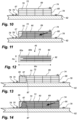
- Figs. 10 and 11 illustrate a known process for forming a spar cap, and the shortcomings thereof.
- a spar cap mould 62 is provided, upon which a stacked arrangement 69 of pultruded fibre plates 70 is arranged.
- a resin inlet 74 is arranged on top of the stacked arrangement 69 close to the second lateral surface 68 thereof.
- a vacuum spiral is placed next to the stacked arrangement 69 close to the first lateral surface 67.
- the resin flow direction is generally from right to left, i.e. from the second to the first lateral surface 67, as indicated by the arrow in Fig. 11 .
- the second lateral surface 68 forms the later leading edge end of the spar cap
- the first lateral surface 67 forms the later trailing edge end of the spar cap.
- a vacuum foil is arranged above the stacked arrangement 69, and tape sealant 78 keeps the vacuum foil 72 in place.
- Resin 80 is infused into the fibre material, as indicated by the darker regions of Fig. 11 .
- a resin flow front is seen within the stacked arrangement 69, close to the first lateral surface. As illustrated in Fig. 11 , there are regions which are insufficiently wetted by the resin, which leads to an inferior product.
- interlayer 82 has a different permeability than the pultruded fibre plates. This leads to challenges in matching the resin impregnation of the fibre plates with the resin impregnation of the interlayers 82. As illustrated in Fig. 12 , this may lead to a spar cap in which part of interlayer comprises dry regions 82a, as opposed to sufficiently wetted regions 82b, which again leads to an inferior end product.
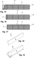
- Figs. 13 and 14 are cross sectional views illustrating the method for manufacturing spar caps according to the present invention.
- a cuboid-shaped insert member 86 is arranged next to the first lateral surface 67 of the stacked arrangement 69, wherein the first insert member 86 is arranged such that its connecting surface 87 abuts against the first lateral surface 67 of the stacked arrangement 69.
- the insert member 86 has the same height as the stacked arrangement 69 of pultruded fibre plates 70.
- Fig. 19 illustrates a perspective view of the cuboid-shaped insert member 86 and its substantially flat connecting surface 87.
- Fig. 19 also illustrates the length Li, the width Wi, and the height Hi of the insert member.
- the length Li of the insert member extends in parallel to the length of the spar cap, i.e. in a substantially spanwise direction in the later blade.
- FIG. 14 A cross section of the demoulded preform 92 of the spar cap is illustrated in Fig. 15 .
- part of the resin-infused insert member can be removed, e.g. by cutting or trimming, resulting in the final spar cap as illustrated in Fig. 16 .
- the entire spar cap is uniformly infused by resin, leading to an improved structural quality of the final product.
- the entire insert member 87 has been removed for forming the final spar cap.
- Figs. 20 and 21 are cross sectional views of a spar cap assembly according to the present invention.
- the spar cap comprises an ear of a lightning protection system.
- a core material 98 such as a foam or balsa wood
- the core material is smoothed out at its edge to remove any hard points where the mesh material of the lightning protection system by bend or break under vacuum.
- this operation usually results in the formation of a gap underneath the ear 96, as seen in Fig. 20 .
- this gap can be filled with a wedge-shaped insert member 86 according to the present invention, prior to resin infusion in the blade mould.
Landscapes
- Engineering & Computer Science (AREA)
- Mechanical Engineering (AREA)
- Chemical & Material Sciences (AREA)
- Composite Materials (AREA)
- Life Sciences & Earth Sciences (AREA)
- Sustainable Development (AREA)
- Sustainable Energy (AREA)
- Combustion & Propulsion (AREA)
- General Engineering & Computer Science (AREA)
- Wind Motors (AREA)
- Moulding By Coating Moulds (AREA)
Claims (15)
- Verfahren zum Herstellen einer faserverstärkten Holmkappe (45) für einen Windkraftanlagenflügel, wobei das Verfahren folgende Schritte umfasst:Bereitstellen eines Holmkappen-Formwerkzeugs (62),Anordnen einer Vielzahl von pultrudierten Faserplatten (70) in dem Holmkappen-Formwerkzeug (62), um eine gestapelte Anordnung (69) von pultrudierten Faserplatten (70) zu bilden, wobei die gestapelte Anordnung (69) eine erste Seitenoberfläche (67) und eine gegenüberliegende zweite Seitenoberfläche (68) umfasst,Anordnen eines ersten Einlageelements (86) neben der ersten Seitenoberfläche (67) der gestapelten Anordnung (69), wobei das erste Einlageelement (86) eine Anschlussfläche (87) umfasst und wobei das erste Einlageelement (86) derart angeordnet ist, dass seine Anschlussfläche an der ersten Seitenoberfläche (67) der gestapelten Anordnung (69) anliegt,optionales Anordnen eines zweiten Einlageelements (88) neben der zweiten Seitenoberfläche (68) der gestapelten Anordnung (69), wobei das zweite Einlageelement (88) eine Anschlussfläche (89) umfasst und wobei das zweite Einlageelement (88) derart angeordnet ist, dass seine Anschlussfläche (89) an der zweiten Seitenoberfläche (68) der gestapelten Anordnung (69) anliegt,Platzieren einer Vakuumfolie (72) über die gestapelte Anordnung (69) und das erste Einlageelement (86) und das optionale zweite Einlageelement (88),Infundieren von Harz in die gestapelte Anordnung (69) und das erste Einlageelement (86) und das optionale zweite Einlageelement (88),Härten des Harzes, um die gestapelte Anordnung (69) und das erste Einlageelement (86) und das optionale zweite Einlageelement (88) zu verbinden, um die faserverstärkte Holmkappe (45) oder einen Vorformling derselben zu bilden,Entfernen der Vakuumfolie (72) undEntformen der faserverstärkten Holmkappe (45) oder des Vorformlings derselben aus dem Holmkappen(45)-Formwerkzeug (62),Beschneiden oder Schleifen mindestens eines Teils des ersten Einlageelements (86) und/oder mindestens eines Teils des zweiten Einlageelements (88) des Vorformlings, um die faserverstärkte Holmkappe (45) zu bilden.
- Verfahren nach Anspruch 1, wobei Harz derart infundiert wird, dass die Harzfließrichtung allgemein von der zweiten Seitenoberfläche (68) zu der ersten Seitenoberfläche (67) der gestapelten Anordnung (69) ist.
- Verfahren nach Ansprüchen 1 oder 2, wobei das Einlageelement dieselbe Höhe aufweist wie die gestapelte Anordnung (69) von pultrudierten Faserplatten (70).
- Verfahren nach einem der vorangehenden Ansprüche, wobei das erste Einlageelement (86) quaderförmig ist.
- Verfahren nach einem der Ansprüche 1-3, wobei das erste Einlageelement (86) und/oder das zweite Einlageelement (88) im Wesentlichen keilförmig sind.
- Verfahren nach einem der vorangehenden Ansprüche, wobei das erste Einlageelement (86) und/oder das zweite Einlageelement (88) aus einem quellfähigen Material hergestellt sind.
- Verfahren nach einem der vorangehenden Ansprüche, wobei das erste Einlageelement (86) und/oder das zweite Einlageelement (88) Balsaholz, einen Schaumstoff oder eine Wabenstruktur umfassen.
- Verfahren nach einem der vorangehenden Ansprüche, wobei das erste Einlageelement (86) und/oder das zweite Einlageelement (88) aus einem Schaumstoff, vorzugsweise Polyethylenterephthalat(PET)-Schaumstoff, hergestellt sind.
- Verfahren nach einem der vorangehenden Ansprüche, wobei eine Zwischenschicht zwischen benachbarten pultrudierten Faserplatten (70) in der gestapelten Anordnung (69) von pultrudierten Faserplatten (70) angeordnet ist.
- Verfahren zum Herstellen eines Windkraftanlagenflügels, wobei das Verfahren folgende Schritte umfasst:Herstellen einer faserverstärkten Holmkappe (45) unter Verwendung des Verfahrens nach einem der vorangehenden Ansprüche,Bereitstellen eines Windkraftanlagenschalenteils mit einer äußeren aerodynamischen Oberfläche und einer gegenüberliegenden inneren Oberfläche,Anordnen der faserverstärkten Holmkappe (45) auf der inneren Oberfläche des Schalenteils undKleben der faserverstärkten Holmkappe (45) an die innere Oberfläche des Schalenteils.
- Faserverstärkte Holmkappe (45) für einen Windkraftanlagenflügel, die mit dem Verfahren nach einem der Ansprüche 1-10 erhalten werden kann, wobei die Holmkappe (45) Folgendes umfasst:eine Vielzahl von pultrudierten Faserplatten (70), die zu einer gestapelten Anordnung (69) von pultrudierten Faserplatten (70) gebildet sind, wobei die gestapelte Anordnung (69) eine erste Seitenoberfläche (67) und eine gegenüberliegende zweite Seitenoberfläche (68) umfasst,ein erstes Einlageelement (86), das neben der ersten Seitenoberfläche (67) der gestapelten Anordnung (69) angeordnet ist, wobei das erste Einlageelement (86) eine Anschlussfläche umfasst und wobei das erste Einlageelement (86) derart angeordnet ist, das seine Anschlussfläche an der ersten Seitenoberfläche (67) der gestapelten Anordnung (69) anliegt, undoptional ein zweites Einlageelement (88), das neben der zweiten Seitenoberfläche (68) der gestapelten Anordnung (69) angeordnet ist, wobei das zweite Einlageelement (88) eine Anschlussfläche umfasst und wobei das zweite Einlageelement (88) derart angeordnet ist, dass seine Anschlussfläche an der zweiten Seitenoberfläche (68) der gestapelten Anordnung (69) anliegt,wobei das erste Einlageelement (86) und optional das zweite Einlageelement (88) durch ein gehärtetes Harz an die gestapelte Anordnung (69) von pultrudierten Faserplatten (70) geklebt sind.
- Faserverstärkte Holmkappe (45) nach Anspruch 11, wobei das erste Einlageelement (86) und/oder das zweite Einlageelement (88) im Wesentlichen keilförmig sind.
- Faserverstärkte Holmkappe (45) nach Anspruch 11 oder 12, wobei das erste Einlageelement (86) und/oder das zweite Einlageelement (88) aus einem quellfähigen Material hergestellt sind.
- Faserverstärkte Holmkappe (45) nach einem der Ansprüche 11-13, wobei das erste Einlageelement (86) und/oder das zweite Einlageelement (88) Balsaholz, einen Schaumstoff oder eine Wabenstruktur umfassen.
- Windkraftanlagenflügel, umfassend eine faserverstärkte Holmkappe (45) nach einem der Ansprüche 11-14.
Priority Applications (7)
| Application Number | Priority Date | Filing Date | Title |
|---|---|---|---|
| PL22151821.0T PL4212324T3 (pl) | 2022-01-17 | 2022-01-17 | Wytwarzanie nakładki na dźwigar łopaty turbiny wiatrowej |
| ES22151821T ES2991969T3 (es) | 2022-01-17 | 2022-01-17 | Fabricación de tapa de larguero de pala de turbina eólica |
| EP22151821.0A EP4212324B1 (de) | 2022-01-17 | 2022-01-17 | Herstellung einer sparrenkappe für windturbinenschaufeln |
| DK22151821.0T DK4212324T3 (da) | 2022-01-17 | 2022-01-17 | Fremstilling af bjælkehætte af vindmøllevinge |
| US18/720,878 US20250050597A1 (en) | 2022-01-17 | 2023-01-13 | Manufacturing of wind turbine blade spar cap |
| CN202380017591.0A CN118556001A (zh) | 2022-01-17 | 2023-01-13 | 风力涡轮叶片翼梁帽的制造 |
| PCT/EP2023/050745 WO2023135256A1 (en) | 2022-01-17 | 2023-01-13 | Manufacturing of wind turbine blade spar cap |
Applications Claiming Priority (1)
| Application Number | Priority Date | Filing Date | Title |
|---|---|---|---|
| EP22151821.0A EP4212324B1 (de) | 2022-01-17 | 2022-01-17 | Herstellung einer sparrenkappe für windturbinenschaufeln |
Publications (2)
| Publication Number | Publication Date |
|---|---|
| EP4212324A1 EP4212324A1 (de) | 2023-07-19 |
| EP4212324B1 true EP4212324B1 (de) | 2024-07-17 |
Family
ID=79686724
Family Applications (1)
| Application Number | Title | Priority Date | Filing Date |
|---|---|---|---|
| EP22151821.0A Active EP4212324B1 (de) | 2022-01-17 | 2022-01-17 | Herstellung einer sparrenkappe für windturbinenschaufeln |
Country Status (7)
| Country | Link |
|---|---|
| US (1) | US20250050597A1 (de) |
| EP (1) | EP4212324B1 (de) |
| CN (1) | CN118556001A (de) |
| DK (1) | DK4212324T3 (de) |
| ES (1) | ES2991969T3 (de) |
| PL (1) | PL4212324T3 (de) |
| WO (1) | WO2023135256A1 (de) |
Cited By (1)
| Publication number | Priority date | Publication date | Assignee | Title |
|---|---|---|---|---|
| EP4157617B1 (de) | 2020-05-25 | 2024-10-09 | LM Wind Power A/S | Verfahren zur herstellung eines holmgurts für ein windturbinenschaufelteil |
Families Citing this family (3)
| Publication number | Priority date | Publication date | Assignee | Title |
|---|---|---|---|---|
| CN117382221B (zh) * | 2023-10-17 | 2024-06-14 | 中材科技(阳江)风电叶片有限公司 | 一种风电叶片碳拉挤主梁的层间灌注结构和灌注方法 |
| EP4549135A1 (de) * | 2023-11-01 | 2025-05-07 | LM Wind Power A/S | Windturbinenschaufel mit verstärkungsstruktur und verfahren zu seiner herstellung |
| EP4628288A1 (de) * | 2024-04-02 | 2025-10-08 | Wobben Properties GmbH | Verfahren zum herstellen eines windenergieanlagen-rotorblattes |
Citations (19)
| Publication number | Priority date | Publication date | Assignee | Title |
|---|---|---|---|---|
| US4942013A (en) | 1989-03-27 | 1990-07-17 | Mcdonnell Douglas Corporation | Vacuum resin impregnation process |
| EP2181834A2 (de) | 2008-11-04 | 2010-05-05 | REpower Systems AG | Rotorblattgurt |
| EP2716904A1 (de) | 2012-10-04 | 2014-04-09 | Areva Blades GmbH | Verbundholmgurt für eine Windturbinenlaufschaufel und Verfahren zur Herstellung des Verbundholmgurts |
| US20140301859A1 (en) | 2011-12-16 | 2014-10-09 | Vestas Wind Systems A/S | Wind turbine blades |
| US20150224721A1 (en) | 2012-10-22 | 2015-08-13 | Senvion Se | Apparatus and method for producing a rotor blade spar cap |
| WO2016015736A1 (en) | 2014-07-31 | 2016-02-04 | Vestas Wind Systems A/S | Improvements relating to reinforcing structures for wind turbine blades |
| EP3029314A1 (de) | 2014-12-04 | 2016-06-08 | General Electric Company | Pultrudierte rotorblattkomponenten mit ineinandergreifenden kanten |
| US20170002792A1 (en) | 2015-06-30 | 2017-01-05 | General Electric Company | Corrugated pre-cured laminate plates for use within wind turbine rotor blades |
| DE102016009640A1 (de) | 2016-08-10 | 2018-02-15 | Senvion Gmbh | Gurt aus vorgefertigten Elementen mit Gelege und ein Verfahren zu seiner Fertigung |
| EP2934864B1 (de) | 2012-12-18 | 2018-03-28 | LM Wind Power International Technology II ApS | Verfahren zur herstellung eines aerodynamischen hüllenteils für eine windturbinenschaufel |
| WO2018091054A1 (en) | 2016-11-17 | 2018-05-24 | Vestas Wind Systems A/S | A reinforcing structure for a wind turbine blade |
| EP3501808A1 (de) | 2017-12-22 | 2019-06-26 | Siemens Gamesa Renewable Energy A/S | Vorgeformte holmgurtanordnung zur einbettung in eine windturbinenrotorschaufel |
| EP3578349A1 (de) | 2018-06-08 | 2019-12-11 | SENVION GmbH | Verfahren und vorrichtung zur herstellung eines rotorblattes für eine windenergieanlage sowie windenergieanlage |
| DE102018006085A1 (de) | 2018-08-02 | 2020-02-06 | Senvion Gmbh | Verjüngter Pultrudatgurt und ein Verfahren zu seiner Herstellung |
| WO2020144054A1 (de) | 2019-01-08 | 2020-07-16 | Senvion Gmbh | Rotorblatt mit wenigstens einem gurt mit einer mehrzahl an pultrudaten und ein verfahren zu seiner herstellung |
| EP3174695B1 (de) | 2014-07-31 | 2020-09-02 | Vestas Wind Systems A/S | Verbundkomponente mit sicherheitskante und herstellungsverfahren |
| US20200300216A1 (en) | 2019-03-21 | 2020-09-24 | Siemens Gamesa Renewable Energy A/S | Wind turbine blade and wind turbine |
| WO2021099763A1 (en) | 2019-11-21 | 2021-05-27 | Spirit AeroSystems (Europe) Limited | Vacuum apparatus and method |
| WO2022096416A1 (en) | 2020-11-03 | 2022-05-12 | Blade Dynamics Limited | Hybrid pultrusion plates for a spar cap of a wind turbine blade |
Family Cites Families (18)
| Publication number | Priority date | Publication date | Assignee | Title |
|---|---|---|---|---|
| US8545657B2 (en) * | 2009-10-30 | 2013-10-01 | Lawrence Livermore National Security, Llc | Methods for tape fabrication of continuous filament composite parts and articles of manufacture thereof |
| US20110135485A1 (en) * | 2009-12-30 | 2011-06-09 | Jing Wang | Spar for a wind turbine rotor blade and method for fabricating the same |
| US9683545B2 (en) * | 2012-05-31 | 2017-06-20 | Vestas Wind Systems A/S | Manufacture of wind turbine blades |
| EP2922690B1 (de) * | 2012-11-20 | 2017-04-19 | Vestas Wind Systems A/S | Windturbinenschaufeln und verfahren zur herstellung davon |
| GB2520079A (en) * | 2013-11-11 | 2015-05-13 | Vestas Wind Sys As | Wind turbine blades |
| GB2520083A (en) * | 2013-11-11 | 2015-05-13 | Vestas Wind Sys As | Wind turbine blades |
| US10428790B2 (en) * | 2013-12-23 | 2019-10-01 | Vestas Wind Systems A/S | Wind turbine blades |
| GB201410429D0 (en) * | 2014-06-11 | 2014-07-23 | Lm Wp Patent Holding As | A tip system for a wild turbine blade |
| US20160146185A1 (en) * | 2014-11-25 | 2016-05-26 | General Electric Company | Methods for manufacturing a spar cap for a wind turbine rotor blade |
| US20160146184A1 (en) * | 2014-11-25 | 2016-05-26 | General Electric Company | Methods of manufacturing rotor blade components for a wind turbine |
| CN107848158B (zh) * | 2015-06-24 | 2020-04-21 | 维斯塔斯风力系统有限公司 | 制作风轮机叶片的方法 |
| US10060411B2 (en) * | 2015-07-22 | 2018-08-28 | General Electric Company | Rotor blade root assembly for a wind turbine |
| US9970304B2 (en) * | 2015-07-22 | 2018-05-15 | General Electric Company | Rotor blade root assembly for a wind turbine |
| US10465653B2 (en) * | 2017-06-21 | 2019-11-05 | General Electric Company | Wind turbine blade with hybrid spar cap and associated method for making |
| US10619622B2 (en) * | 2017-06-21 | 2020-04-14 | General Electric Company | Wind turbine blade with hybrid spar cap and associated method for making |
| US10677216B2 (en) * | 2017-10-24 | 2020-06-09 | General Electric Company | Wind turbine rotor blade components formed using pultruded rods |
| EP3569394A1 (de) * | 2018-05-17 | 2019-11-20 | Siemens Gamesa Renewable Energy A/S | Verfahren zur herstellung von holmkappen |
| US20210332789A1 (en) * | 2020-04-28 | 2021-10-28 | Lm Wind Power A/S | Wind turbine rotor blade with covered access window |
-
2022
- 2022-01-17 DK DK22151821.0T patent/DK4212324T3/da active
- 2022-01-17 ES ES22151821T patent/ES2991969T3/es active Active
- 2022-01-17 EP EP22151821.0A patent/EP4212324B1/de active Active
- 2022-01-17 PL PL22151821.0T patent/PL4212324T3/pl unknown
-
2023
- 2023-01-13 WO PCT/EP2023/050745 patent/WO2023135256A1/en not_active Ceased
- 2023-01-13 US US18/720,878 patent/US20250050597A1/en active Pending
- 2023-01-13 CN CN202380017591.0A patent/CN118556001A/zh active Pending
Patent Citations (19)
| Publication number | Priority date | Publication date | Assignee | Title |
|---|---|---|---|---|
| US4942013A (en) | 1989-03-27 | 1990-07-17 | Mcdonnell Douglas Corporation | Vacuum resin impregnation process |
| EP2181834A2 (de) | 2008-11-04 | 2010-05-05 | REpower Systems AG | Rotorblattgurt |
| US20140301859A1 (en) | 2011-12-16 | 2014-10-09 | Vestas Wind Systems A/S | Wind turbine blades |
| EP2716904A1 (de) | 2012-10-04 | 2014-04-09 | Areva Blades GmbH | Verbundholmgurt für eine Windturbinenlaufschaufel und Verfahren zur Herstellung des Verbundholmgurts |
| US20150224721A1 (en) | 2012-10-22 | 2015-08-13 | Senvion Se | Apparatus and method for producing a rotor blade spar cap |
| EP2934864B1 (de) | 2012-12-18 | 2018-03-28 | LM Wind Power International Technology II ApS | Verfahren zur herstellung eines aerodynamischen hüllenteils für eine windturbinenschaufel |
| EP3174695B1 (de) | 2014-07-31 | 2020-09-02 | Vestas Wind Systems A/S | Verbundkomponente mit sicherheitskante und herstellungsverfahren |
| WO2016015736A1 (en) | 2014-07-31 | 2016-02-04 | Vestas Wind Systems A/S | Improvements relating to reinforcing structures for wind turbine blades |
| EP3029314A1 (de) | 2014-12-04 | 2016-06-08 | General Electric Company | Pultrudierte rotorblattkomponenten mit ineinandergreifenden kanten |
| US20170002792A1 (en) | 2015-06-30 | 2017-01-05 | General Electric Company | Corrugated pre-cured laminate plates for use within wind turbine rotor blades |
| DE102016009640A1 (de) | 2016-08-10 | 2018-02-15 | Senvion Gmbh | Gurt aus vorgefertigten Elementen mit Gelege und ein Verfahren zu seiner Fertigung |
| WO2018091054A1 (en) | 2016-11-17 | 2018-05-24 | Vestas Wind Systems A/S | A reinforcing structure for a wind turbine blade |
| EP3501808A1 (de) | 2017-12-22 | 2019-06-26 | Siemens Gamesa Renewable Energy A/S | Vorgeformte holmgurtanordnung zur einbettung in eine windturbinenrotorschaufel |
| EP3578349A1 (de) | 2018-06-08 | 2019-12-11 | SENVION GmbH | Verfahren und vorrichtung zur herstellung eines rotorblattes für eine windenergieanlage sowie windenergieanlage |
| DE102018006085A1 (de) | 2018-08-02 | 2020-02-06 | Senvion Gmbh | Verjüngter Pultrudatgurt und ein Verfahren zu seiner Herstellung |
| WO2020144054A1 (de) | 2019-01-08 | 2020-07-16 | Senvion Gmbh | Rotorblatt mit wenigstens einem gurt mit einer mehrzahl an pultrudaten und ein verfahren zu seiner herstellung |
| US20200300216A1 (en) | 2019-03-21 | 2020-09-24 | Siemens Gamesa Renewable Energy A/S | Wind turbine blade and wind turbine |
| WO2021099763A1 (en) | 2019-11-21 | 2021-05-27 | Spirit AeroSystems (Europe) Limited | Vacuum apparatus and method |
| WO2022096416A1 (en) | 2020-11-03 | 2022-05-12 | Blade Dynamics Limited | Hybrid pultrusion plates for a spar cap of a wind turbine blade |
Non-Patent Citations (8)
| Title |
|---|
| ANONYMOUS: "Vacuum assisted resin transfer molding", WIKIPEDIA, pages 1 - 3, XP093349891, Retrieved from the Internet <URL:https://en.wikipedia.org/w/index.php?title=Vacuum_assisted_resin_transfer_molding&oldid=1012408578> |
| AVK – INDUSTRIEVEREINIGUNG VERSTÄRKTE KUNSTSTOFFE E. V.: "Handbuch Faserverbundkunststoffe/Composites : Grundlagen, Verarbeitung, Anwendungen", 12 September 2013, SPRINGER VIEWEG, Wiesbaden, ISBN: 978-3-658-02754-4, article "6.16.3 Fügetechnik", pages: 525 - 531, XP009560724, DOI: 10.1007/978-3-658-02755-1 |
| B. T. ÅSTRÖM: "Manufacturing of polymer composites", 1 January 1997, LONDON : CHAPMAN & HALL, 1997. , UK , ISBN: 0-412-81960-0, article B. T. ASTRÖM: "4.2.3 Liquid Molding", pages: 219 - 234, XP009561553 |
| B. T. ÅSTRÖM: "Manufacturing of polymer composites", 1 January 1997, LONDON : CHAPMAN & HALL, 1997. , UK , ISBN: 0-412-81960-0, article B.T. ASTRÖM: "5.1 Machining", pages: 307 - 326, XP009561554 |
| F. L. MATTHEWS AND R. D. RAWLINGS: "Composite Materials: Engineering and Science", 1 January 1994, CHAPMAN & HALL, ISBN: 0412559609, article MATTHEWS, F. L. ; RAWLINGS, REES D: "POLYMER MATRIX COMPOSITES", pages: 182 - 185, XP009560718 |
| MURDY PAUL, DOLSON JACK, MILLER DAVID, HUGHES SCOTT, BEACH RYAN: "Leveraging the Advantages of Additive Manufacturing to Produce Advanced Hybrid Composite Structures for Marine Energy Systems", APPLIED SCIENCES, MDPI SWITZERLAND, vol. 11, no. 3, pages 1336, XP093271815, ISSN: 2076-3417, DOI: 10.3390/app11031336 |
| PARKER B. M.: "THE USE OF PRIMERS IN THE ADHESIVE BONDING OF CARBON-FIBRE REINFORCED COMPOSITES", ROYAL AIROSPACE ESTABLISHMENT, TECHNICAL REPORT 88048, 1 July 1988 (1988-07-01), XP093271819, Retrieved from the Internet <URL:https://apps.dtic.mil/sti/tr/pdf/ADA202542.pdf> |
| STOLL FREDERICK C.: "Optimal Design of Sandwich Core for Wind Turbine Blade Buckling Resistance", 32ND ASME WIND ENERGY SYMPOSIUM, AMERICAN INSTITUTE OF AERONAUTICS AND ASTRONAUTICS, RESTON, VIRGINIA, 13 January 2014 (2014-01-13), Reston, Virginia, XP093271817, ISBN: 978-1-62410-313-1, DOI: 10.2514/6.2014-0175 |
Cited By (1)
| Publication number | Priority date | Publication date | Assignee | Title |
|---|---|---|---|---|
| EP4157617B1 (de) | 2020-05-25 | 2024-10-09 | LM Wind Power A/S | Verfahren zur herstellung eines holmgurts für ein windturbinenschaufelteil |
Also Published As
| Publication number | Publication date |
|---|---|
| DK4212324T3 (da) | 2024-10-21 |
| WO2023135256A1 (en) | 2023-07-20 |
| CN118556001A (zh) | 2024-08-27 |
| EP4212324A1 (de) | 2023-07-19 |
| PL4212324T3 (pl) | 2024-11-25 |
| ES2991969T3 (es) | 2024-12-05 |
| US20250050597A1 (en) | 2025-02-13 |
Similar Documents
| Publication | Publication Date | Title |
|---|---|---|
| EP4212324B1 (de) | Herstellung einer sparrenkappe für windturbinenschaufeln | |
| US11607826B2 (en) | Method of manufacturing at least two preforms for moulding a wind turbine blade | |
| EP2934857B1 (de) | Windturbinenschaufel mit aerodynamischer schaufelverkleidung mit aussparung und vorgefertigter holmkappe | |
| US8216500B2 (en) | Method of manufacturing pre-bent wind turbine blades | |
| US20220228553A1 (en) | Method for manufacturing a wind turbine blade and wind turbine blade | |
| US20190195190A1 (en) | Pultruded fibrous composite strips having corrugated profiles for wind turbine blade spar caps | |
| EP3423266B1 (de) | Verfahren zum formen eines mantelteils einer windturbinenschaufel | |
| US12589556B2 (en) | Pultruded fibre-reinforced strip for a reinforced structure, such as a spar cap | |
| US20240001632A1 (en) | Method of manufacturing a spar cap for a wind turbine blade | |
| EP3643912B1 (de) | Windturbinenschaufel mit mehreren holmkappen | |
| US12053939B2 (en) | Mould tool for manufacture of a wind turbine blade | |
| CA3010680A1 (en) | Method of molding a shell part of a wind turbine blade | |
| EP3946909B1 (de) | Herstellung eines verstärkten mantelteils einer windturbinenschaufel | |
| US12071925B2 (en) | Wind turbine blade with reinforcing structure | |
| US12540597B2 (en) | Spar cap with tapering and serrated end section | |
| US12350893B2 (en) | Method of manufacturing a wind turbine blade | |
| US20240399678A1 (en) | Spar cap for a wind turbine blade | |
| US12247543B2 (en) | Damage tolerant cover sheet for premanufactured spar cap | |
| EP4549135A1 (de) | Windturbinenschaufel mit verstärkungsstruktur und verfahren zu seiner herstellung | |
| EP4234192A1 (de) | Verfahren zur herstellung von turbinenschaufelvorformen mit komplexen geometrien | |
| WO2025021460A1 (en) | Separation comb for avoiding misalignments of pultrusions in a spar cap |
Legal Events
| Date | Code | Title | Description |
|---|---|---|---|
| PUAI | Public reference made under article 153(3) epc to a published international application that has entered the european phase |
Free format text: ORIGINAL CODE: 0009012 |
|
| STAA | Information on the status of an ep patent application or granted ep patent |
Free format text: STATUS: THE APPLICATION HAS BEEN PUBLISHED |
|
| AK | Designated contracting states |
Kind code of ref document: A1 Designated state(s): AL AT BE BG CH CY CZ DE DK EE ES FI FR GB GR HR HU IE IS IT LI LT LU LV MC MK MT NL NO PL PT RO RS SE SI SK SM TR |
|
| STAA | Information on the status of an ep patent application or granted ep patent |
Free format text: STATUS: REQUEST FOR EXAMINATION WAS MADE |
|
| 17P | Request for examination filed |
Effective date: 20240109 |
|
| RAV | Requested validation state of the european patent: fee paid |
Extension state: MA Effective date: 20240109 |
|
| RBV | Designated contracting states (corrected) |
Designated state(s): AL AT BE BG CH CY CZ DE DK EE ES FI FR GB GR HR HU IE IS IT LI LT LU LV MC MK MT NL NO PL PT RO RS SE SI SK SM TR |
|
| GRAP | Despatch of communication of intention to grant a patent |
Free format text: ORIGINAL CODE: EPIDOSNIGR1 |
|
| STAA | Information on the status of an ep patent application or granted ep patent |
Free format text: STATUS: GRANT OF PATENT IS INTENDED |
|
| RIC1 | Information provided on ipc code assigned before grant |
Ipc: B29C 70/52 20060101ALN20240207BHEP Ipc: B29L 31/08 20060101ALN20240207BHEP Ipc: F03D 1/06 20060101ALI20240207BHEP Ipc: B29C 70/34 20060101ALI20240207BHEP Ipc: B29D 99/00 20100101AFI20240207BHEP |
|
| INTG | Intention to grant announced |
Effective date: 20240311 |
|
| GRAS | Grant fee paid |
Free format text: ORIGINAL CODE: EPIDOSNIGR3 |
|
| GRAA | (expected) grant |
Free format text: ORIGINAL CODE: 0009210 |
|
| STAA | Information on the status of an ep patent application or granted ep patent |
Free format text: STATUS: THE PATENT HAS BEEN GRANTED |
|
| AK | Designated contracting states |
Kind code of ref document: B1 Designated state(s): AL AT BE BG CH CY CZ DE DK EE ES FI FR GB GR HR HU IE IS IT LI LT LU LV MC MK MT NL NO PL PT RO RS SE SI SK SM TR |
|
| P01 | Opt-out of the competence of the unified patent court (upc) registered |
Free format text: CASE NUMBER: APP_36320/2024 Effective date: 20240618 |
|
| REG | Reference to a national code |
Ref country code: CH Ref legal event code: EP |
|
| REG | Reference to a national code |
Ref country code: DE Ref legal event code: R096 Ref document number: 602022004523 Country of ref document: DE |
|
| REG | Reference to a national code |
Ref country code: IE Ref legal event code: FG4D |
|
| REG | Reference to a national code |
Ref country code: DK Ref legal event code: T3 Effective date: 20241016 |
|
| REG | Reference to a national code |
Ref country code: LT Ref legal event code: MG9D |
|
| REG | Reference to a national code |
Ref country code: NL Ref legal event code: MP Effective date: 20240717 |
|
| REG | Reference to a national code |
Ref country code: ES Ref legal event code: FG2A Ref document number: 2991969 Country of ref document: ES Kind code of ref document: T3 Effective date: 20241205 |
|
| PG25 | Lapsed in a contracting state [announced via postgrant information from national office to epo] |
Ref country code: PT Free format text: LAPSE BECAUSE OF FAILURE TO SUBMIT A TRANSLATION OF THE DESCRIPTION OR TO PAY THE FEE WITHIN THE PRESCRIBED TIME-LIMIT Effective date: 20241118 |
|
| REG | Reference to a national code |
Ref country code: AT Ref legal event code: MK05 Ref document number: 1703751 Country of ref document: AT Kind code of ref document: T Effective date: 20240717 |
|
| PG25 | Lapsed in a contracting state [announced via postgrant information from national office to epo] |
Ref country code: NL Free format text: LAPSE BECAUSE OF FAILURE TO SUBMIT A TRANSLATION OF THE DESCRIPTION OR TO PAY THE FEE WITHIN THE PRESCRIBED TIME-LIMIT Effective date: 20240717 |
|
| PG25 | Lapsed in a contracting state [announced via postgrant information from national office to epo] |
Ref country code: PT Free format text: LAPSE BECAUSE OF FAILURE TO SUBMIT A TRANSLATION OF THE DESCRIPTION OR TO PAY THE FEE WITHIN THE PRESCRIBED TIME-LIMIT Effective date: 20241118 Ref country code: NL Free format text: LAPSE BECAUSE OF FAILURE TO SUBMIT A TRANSLATION OF THE DESCRIPTION OR TO PAY THE FEE WITHIN THE PRESCRIBED TIME-LIMIT Effective date: 20240717 |
|
| PG25 | Lapsed in a contracting state [announced via postgrant information from national office to epo] |
Ref country code: NO Free format text: LAPSE BECAUSE OF FAILURE TO SUBMIT A TRANSLATION OF THE DESCRIPTION OR TO PAY THE FEE WITHIN THE PRESCRIBED TIME-LIMIT Effective date: 20241017 |
|
| PG25 | Lapsed in a contracting state [announced via postgrant information from national office to epo] |
Ref country code: FI Free format text: LAPSE BECAUSE OF FAILURE TO SUBMIT A TRANSLATION OF THE DESCRIPTION OR TO PAY THE FEE WITHIN THE PRESCRIBED TIME-LIMIT Effective date: 20240717 Ref country code: GR Free format text: LAPSE BECAUSE OF FAILURE TO SUBMIT A TRANSLATION OF THE DESCRIPTION OR TO PAY THE FEE WITHIN THE PRESCRIBED TIME-LIMIT Effective date: 20241018 |
|
| PG25 | Lapsed in a contracting state [announced via postgrant information from national office to epo] |
Ref country code: BG Free format text: LAPSE BECAUSE OF FAILURE TO SUBMIT A TRANSLATION OF THE DESCRIPTION OR TO PAY THE FEE WITHIN THE PRESCRIBED TIME-LIMIT Effective date: 20240717 |
|
| PG25 | Lapsed in a contracting state [announced via postgrant information from national office to epo] |
Ref country code: LV Free format text: LAPSE BECAUSE OF FAILURE TO SUBMIT A TRANSLATION OF THE DESCRIPTION OR TO PAY THE FEE WITHIN THE PRESCRIBED TIME-LIMIT Effective date: 20240717 |
|
| PG25 | Lapsed in a contracting state [announced via postgrant information from national office to epo] |
Ref country code: AT Free format text: LAPSE BECAUSE OF FAILURE TO SUBMIT A TRANSLATION OF THE DESCRIPTION OR TO PAY THE FEE WITHIN THE PRESCRIBED TIME-LIMIT Effective date: 20240717 Ref country code: IS Free format text: LAPSE BECAUSE OF FAILURE TO SUBMIT A TRANSLATION OF THE DESCRIPTION OR TO PAY THE FEE WITHIN THE PRESCRIBED TIME-LIMIT Effective date: 20241117 |
|
| PG25 | Lapsed in a contracting state [announced via postgrant information from national office to epo] |
Ref country code: HR Free format text: LAPSE BECAUSE OF FAILURE TO SUBMIT A TRANSLATION OF THE DESCRIPTION OR TO PAY THE FEE WITHIN THE PRESCRIBED TIME-LIMIT Effective date: 20240717 |
|
| PG25 | Lapsed in a contracting state [announced via postgrant information from national office to epo] |
Ref country code: RS Free format text: LAPSE BECAUSE OF FAILURE TO SUBMIT A TRANSLATION OF THE DESCRIPTION OR TO PAY THE FEE WITHIN THE PRESCRIBED TIME-LIMIT Effective date: 20241017 |
|
| PG25 | Lapsed in a contracting state [announced via postgrant information from national office to epo] |
Ref country code: RS Free format text: LAPSE BECAUSE OF FAILURE TO SUBMIT A TRANSLATION OF THE DESCRIPTION OR TO PAY THE FEE WITHIN THE PRESCRIBED TIME-LIMIT Effective date: 20241017 Ref country code: NO Free format text: LAPSE BECAUSE OF FAILURE TO SUBMIT A TRANSLATION OF THE DESCRIPTION OR TO PAY THE FEE WITHIN THE PRESCRIBED TIME-LIMIT Effective date: 20241017 Ref country code: LV Free format text: LAPSE BECAUSE OF FAILURE TO SUBMIT A TRANSLATION OF THE DESCRIPTION OR TO PAY THE FEE WITHIN THE PRESCRIBED TIME-LIMIT Effective date: 20240717 Ref country code: IS Free format text: LAPSE BECAUSE OF FAILURE TO SUBMIT A TRANSLATION OF THE DESCRIPTION OR TO PAY THE FEE WITHIN THE PRESCRIBED TIME-LIMIT Effective date: 20241117 Ref country code: HR Free format text: LAPSE BECAUSE OF FAILURE TO SUBMIT A TRANSLATION OF THE DESCRIPTION OR TO PAY THE FEE WITHIN THE PRESCRIBED TIME-LIMIT Effective date: 20240717 Ref country code: GR Free format text: LAPSE BECAUSE OF FAILURE TO SUBMIT A TRANSLATION OF THE DESCRIPTION OR TO PAY THE FEE WITHIN THE PRESCRIBED TIME-LIMIT Effective date: 20241018 Ref country code: FI Free format text: LAPSE BECAUSE OF FAILURE TO SUBMIT A TRANSLATION OF THE DESCRIPTION OR TO PAY THE FEE WITHIN THE PRESCRIBED TIME-LIMIT Effective date: 20240717 Ref country code: BG Free format text: LAPSE BECAUSE OF FAILURE TO SUBMIT A TRANSLATION OF THE DESCRIPTION OR TO PAY THE FEE WITHIN THE PRESCRIBED TIME-LIMIT Effective date: 20240717 Ref country code: AT Free format text: LAPSE BECAUSE OF FAILURE TO SUBMIT A TRANSLATION OF THE DESCRIPTION OR TO PAY THE FEE WITHIN THE PRESCRIBED TIME-LIMIT Effective date: 20240717 |
|
| PG25 | Lapsed in a contracting state [announced via postgrant information from national office to epo] |
Ref country code: SM Free format text: LAPSE BECAUSE OF FAILURE TO SUBMIT A TRANSLATION OF THE DESCRIPTION OR TO PAY THE FEE WITHIN THE PRESCRIBED TIME-LIMIT Effective date: 20240717 Ref country code: RO Free format text: LAPSE BECAUSE OF FAILURE TO SUBMIT A TRANSLATION OF THE DESCRIPTION OR TO PAY THE FEE WITHIN THE PRESCRIBED TIME-LIMIT Effective date: 20240717 |
|
| REG | Reference to a national code |
Ref country code: DE Ref legal event code: R026 Ref document number: 602022004523 Country of ref document: DE |
|
| PLBI | Opposition filed |
Free format text: ORIGINAL CODE: 0009260 |
|
| PG25 | Lapsed in a contracting state [announced via postgrant information from national office to epo] |
Ref country code: EE Free format text: LAPSE BECAUSE OF FAILURE TO SUBMIT A TRANSLATION OF THE DESCRIPTION OR TO PAY THE FEE WITHIN THE PRESCRIBED TIME-LIMIT Effective date: 20240717 |
|
| PG25 | Lapsed in a contracting state [announced via postgrant information from national office to epo] |
Ref country code: CZ Free format text: LAPSE BECAUSE OF FAILURE TO SUBMIT A TRANSLATION OF THE DESCRIPTION OR TO PAY THE FEE WITHIN THE PRESCRIBED TIME-LIMIT Effective date: 20240717 |
|
| PLAB | Opposition data, opponent's data or that of the opponent's representative modified |
Free format text: ORIGINAL CODE: 0009299OPPO |
|
| PG25 | Lapsed in a contracting state [announced via postgrant information from national office to epo] |
Ref country code: SK Free format text: LAPSE BECAUSE OF FAILURE TO SUBMIT A TRANSLATION OF THE DESCRIPTION OR TO PAY THE FEE WITHIN THE PRESCRIBED TIME-LIMIT Effective date: 20240717 |
|
| PLAX | Notice of opposition and request to file observation + time limit sent |
Free format text: ORIGINAL CODE: EPIDOSNOBS2 |
|
| 26 | Opposition filed |
Opponent name: WOBBEN PROPERTIES GMBH Effective date: 20250417 |
|
| R26 | Opposition filed (corrected) |
Opponent name: WOBBEN PROPERTIES GMBH Effective date: 20250417 |
|
| REG | Reference to a national code |
Ref country code: CH Ref legal event code: PL |
|
| PLBB | Reply of patent proprietor to notice(s) of opposition received |
Free format text: ORIGINAL CODE: EPIDOSNOBS3 |
|
| PG25 | Lapsed in a contracting state [announced via postgrant information from national office to epo] |
Ref country code: SE Free format text: LAPSE BECAUSE OF FAILURE TO SUBMIT A TRANSLATION OF THE DESCRIPTION OR TO PAY THE FEE WITHIN THE PRESCRIBED TIME-LIMIT Effective date: 20240717 |
|
| PG25 | Lapsed in a contracting state [announced via postgrant information from national office to epo] |
Ref country code: LU Free format text: LAPSE BECAUSE OF NON-PAYMENT OF DUE FEES Effective date: 20250117 Ref country code: MC Free format text: LAPSE BECAUSE OF FAILURE TO SUBMIT A TRANSLATION OF THE DESCRIPTION OR TO PAY THE FEE WITHIN THE PRESCRIBED TIME-LIMIT Effective date: 20240717 |
|
| PG25 | Lapsed in a contracting state [announced via postgrant information from national office to epo] |
Ref country code: BE Free format text: LAPSE BECAUSE OF NON-PAYMENT OF DUE FEES Effective date: 20250131 |
|
| PG25 | Lapsed in a contracting state [announced via postgrant information from national office to epo] |
Ref country code: CH Free format text: LAPSE BECAUSE OF NON-PAYMENT OF DUE FEES Effective date: 20250131 |
|
| REG | Reference to a national code |
Ref country code: BE Ref legal event code: MM Effective date: 20250131 |
|
| PGFP | Annual fee paid to national office [announced via postgrant information from national office to epo] |
Ref country code: GB Payment date: 20251220 Year of fee payment: 5 |
|
| PGFP | Annual fee paid to national office [announced via postgrant information from national office to epo] |
Ref country code: DK Payment date: 20251217 Year of fee payment: 5 |
|
| PGFP | Annual fee paid to national office [announced via postgrant information from national office to epo] |
Ref country code: FR Payment date: 20251217 Year of fee payment: 5 |
|
| PG25 | Lapsed in a contracting state [announced via postgrant information from national office to epo] |
Ref country code: IE Free format text: LAPSE BECAUSE OF NON-PAYMENT OF DUE FEES Effective date: 20250117 |
|
| PGFP | Annual fee paid to national office [announced via postgrant information from national office to epo] |
Ref country code: PL Payment date: 20251217 Year of fee payment: 5 |
|
| PG25 | Lapsed in a contracting state [announced via postgrant information from national office to epo] |
Ref country code: IT Free format text: LAPSE BECAUSE OF FAILURE TO SUBMIT A TRANSLATION OF THE DESCRIPTION OR TO PAY THE FEE WITHIN THE PRESCRIBED TIME-LIMIT Effective date: 20240717 |
|
| PGFP | Annual fee paid to national office [announced via postgrant information from national office to epo] |
Ref country code: ES Payment date: 20260202 Year of fee payment: 5 |
|
| PGFP | Annual fee paid to national office [announced via postgrant information from national office to epo] |
Ref country code: DE Payment date: 20251217 Year of fee payment: 5 |
|
| VS25 | Lapsed in a validation state [announced via postgrant information from nat. office to epo] |
Ref country code: MA Free format text: LAPSE BECAUSE OF FAILURE TO SUBMIT A TRANSLATION OF THE DESCRIPTION OR TO PAY THE FEE WITHIN THE PRESCRIBED TIME-LIMIT Effective date: 20240717 |