EP4158237B1 - Verankerungsvorrichtung zum halten von isolierblöcken - Google Patents
Verankerungsvorrichtung zum halten von isolierblöcken Download PDFInfo
- Publication number
- EP4158237B1 EP4158237B1 EP21728878.6A EP21728878A EP4158237B1 EP 4158237 B1 EP4158237 B1 EP 4158237B1 EP 21728878 A EP21728878 A EP 21728878A EP 4158237 B1 EP4158237 B1 EP 4158237B1
- Authority
- EP
- European Patent Office
- Prior art keywords
- plate
- lower plate
- anchor device
- anchor
- tank
- Prior art date
- Legal status (The legal status is an assumption and is not a legal conclusion. Google has not performed a legal analysis and makes no representation as to the accuracy of the status listed.)
- Active
Links
Images






Classifications
-
- B—PERFORMING OPERATIONS; TRANSPORTING
- B63—SHIPS OR OTHER WATERBORNE VESSELS; RELATED EQUIPMENT
- B63B—SHIPS OR OTHER WATERBORNE VESSELS; EQUIPMENT FOR SHIPPING
- B63B25/00—Load-accommodating arrangements, e.g. stowing, trimming; Vessels characterised thereby
- B63B25/02—Load-accommodating arrangements, e.g. stowing, trimming; Vessels characterised thereby for bulk goods
- B63B25/08—Load-accommodating arrangements, e.g. stowing, trimming; Vessels characterised thereby for bulk goods fluid
- B63B25/12—Load-accommodating arrangements, e.g. stowing, trimming; Vessels characterised thereby for bulk goods fluid closed
- B63B25/16—Load-accommodating arrangements, e.g. stowing, trimming; Vessels characterised thereby for bulk goods fluid closed heat-insulated
-
- F—MECHANICAL ENGINEERING; LIGHTING; HEATING; WEAPONS; BLASTING
- F17—STORING OR DISTRIBUTING GASES OR LIQUIDS
- F17C—VESSELS FOR CONTAINING OR STORING COMPRESSED, LIQUEFIED OR SOLIDIFIED GASES; FIXED-CAPACITY GAS-HOLDERS; FILLING VESSELS WITH, OR DISCHARGING FROM VESSELS, COMPRESSED, LIQUEFIED, OR SOLIDIFIED GASES
- F17C3/00—Vessels not under pressure
- F17C3/02—Vessels not under pressure with provision for thermal insulation
- F17C3/025—Bulk storage in barges or on ships
- F17C3/027—Wallpanels for so-called membrane tanks
-
- F—MECHANICAL ENGINEERING; LIGHTING; HEATING; WEAPONS; BLASTING
- F17—STORING OR DISTRIBUTING GASES OR LIQUIDS
- F17C—VESSELS FOR CONTAINING OR STORING COMPRESSED, LIQUEFIED OR SOLIDIFIED GASES; FIXED-CAPACITY GAS-HOLDERS; FILLING VESSELS WITH, OR DISCHARGING FROM VESSELS, COMPRESSED, LIQUEFIED, OR SOLIDIFIED GASES
- F17C3/00—Vessels not under pressure
- F17C3/02—Vessels not under pressure with provision for thermal insulation
- F17C3/04—Vessels not under pressure with provision for thermal insulation by insulating layers
-
- F—MECHANICAL ENGINEERING; LIGHTING; HEATING; WEAPONS; BLASTING
- F17—STORING OR DISTRIBUTING GASES OR LIQUIDS
- F17C—VESSELS FOR CONTAINING OR STORING COMPRESSED, LIQUEFIED OR SOLIDIFIED GASES; FIXED-CAPACITY GAS-HOLDERS; FILLING VESSELS WITH, OR DISCHARGING FROM VESSELS, COMPRESSED, LIQUEFIED, OR SOLIDIFIED GASES
- F17C2201/00—Vessel construction, in particular geometry, arrangement or size
- F17C2201/01—Shape
- F17C2201/0147—Shape complex
- F17C2201/0157—Polygonal
-
- F—MECHANICAL ENGINEERING; LIGHTING; HEATING; WEAPONS; BLASTING
- F17—STORING OR DISTRIBUTING GASES OR LIQUIDS
- F17C—VESSELS FOR CONTAINING OR STORING COMPRESSED, LIQUEFIED OR SOLIDIFIED GASES; FIXED-CAPACITY GAS-HOLDERS; FILLING VESSELS WITH, OR DISCHARGING FROM VESSELS, COMPRESSED, LIQUEFIED, OR SOLIDIFIED GASES
- F17C2201/00—Vessel construction, in particular geometry, arrangement or size
- F17C2201/05—Size
- F17C2201/052—Size large (>1000 m3)
-
- F—MECHANICAL ENGINEERING; LIGHTING; HEATING; WEAPONS; BLASTING
- F17—STORING OR DISTRIBUTING GASES OR LIQUIDS
- F17C—VESSELS FOR CONTAINING OR STORING COMPRESSED, LIQUEFIED OR SOLIDIFIED GASES; FIXED-CAPACITY GAS-HOLDERS; FILLING VESSELS WITH, OR DISCHARGING FROM VESSELS, COMPRESSED, LIQUEFIED, OR SOLIDIFIED GASES
- F17C2203/00—Vessel construction, in particular walls or details thereof
- F17C2203/03—Thermal insulations
- F17C2203/0304—Thermal insulations by solid means
- F17C2203/0329—Foam
- F17C2203/0333—Polyurethane
-
- F—MECHANICAL ENGINEERING; LIGHTING; HEATING; WEAPONS; BLASTING
- F17—STORING OR DISTRIBUTING GASES OR LIQUIDS
- F17C—VESSELS FOR CONTAINING OR STORING COMPRESSED, LIQUEFIED OR SOLIDIFIED GASES; FIXED-CAPACITY GAS-HOLDERS; FILLING VESSELS WITH, OR DISCHARGING FROM VESSELS, COMPRESSED, LIQUEFIED, OR SOLIDIFIED GASES
- F17C2203/00—Vessel construction, in particular walls or details thereof
- F17C2203/03—Thermal insulations
- F17C2203/0304—Thermal insulations by solid means
- F17C2203/0345—Fibres
- F17C2203/035—Glass wool
-
- F—MECHANICAL ENGINEERING; LIGHTING; HEATING; WEAPONS; BLASTING
- F17—STORING OR DISTRIBUTING GASES OR LIQUIDS
- F17C—VESSELS FOR CONTAINING OR STORING COMPRESSED, LIQUEFIED OR SOLIDIFIED GASES; FIXED-CAPACITY GAS-HOLDERS; FILLING VESSELS WITH, OR DISCHARGING FROM VESSELS, COMPRESSED, LIQUEFIED, OR SOLIDIFIED GASES
- F17C2203/00—Vessel construction, in particular walls or details thereof
- F17C2203/03—Thermal insulations
- F17C2203/0304—Thermal insulations by solid means
- F17C2203/0358—Thermal insulations by solid means in form of panels
-
- F—MECHANICAL ENGINEERING; LIGHTING; HEATING; WEAPONS; BLASTING
- F17—STORING OR DISTRIBUTING GASES OR LIQUIDS
- F17C—VESSELS FOR CONTAINING OR STORING COMPRESSED, LIQUEFIED OR SOLIDIFIED GASES; FIXED-CAPACITY GAS-HOLDERS; FILLING VESSELS WITH, OR DISCHARGING FROM VESSELS, COMPRESSED, LIQUEFIED, OR SOLIDIFIED GASES
- F17C2203/00—Vessel construction, in particular walls or details thereof
- F17C2203/06—Materials for walls or layers thereof; Properties or structures of walls or their materials
- F17C2203/0602—Wall structures; Special features thereof
-
- F—MECHANICAL ENGINEERING; LIGHTING; HEATING; WEAPONS; BLASTING
- F17—STORING OR DISTRIBUTING GASES OR LIQUIDS
- F17C—VESSELS FOR CONTAINING OR STORING COMPRESSED, LIQUEFIED OR SOLIDIFIED GASES; FIXED-CAPACITY GAS-HOLDERS; FILLING VESSELS WITH, OR DISCHARGING FROM VESSELS, COMPRESSED, LIQUEFIED, OR SOLIDIFIED GASES
- F17C2203/00—Vessel construction, in particular walls or details thereof
- F17C2203/06—Materials for walls or layers thereof; Properties or structures of walls or their materials
- F17C2203/0602—Wall structures; Special features thereof
- F17C2203/0612—Wall structures
- F17C2203/0626—Multiple walls
-
- F—MECHANICAL ENGINEERING; LIGHTING; HEATING; WEAPONS; BLASTING
- F17—STORING OR DISTRIBUTING GASES OR LIQUIDS
- F17C—VESSELS FOR CONTAINING OR STORING COMPRESSED, LIQUEFIED OR SOLIDIFIED GASES; FIXED-CAPACITY GAS-HOLDERS; FILLING VESSELS WITH, OR DISCHARGING FROM VESSELS, COMPRESSED, LIQUEFIED, OR SOLIDIFIED GASES
- F17C2209/00—Vessel construction, in particular methods of manufacturing
- F17C2209/22—Assembling processes
- F17C2209/228—Assembling processes by screws, bolts or rivets
-
- F—MECHANICAL ENGINEERING; LIGHTING; HEATING; WEAPONS; BLASTING
- F17—STORING OR DISTRIBUTING GASES OR LIQUIDS
- F17C—VESSELS FOR CONTAINING OR STORING COMPRESSED, LIQUEFIED OR SOLIDIFIED GASES; FIXED-CAPACITY GAS-HOLDERS; FILLING VESSELS WITH, OR DISCHARGING FROM VESSELS, COMPRESSED, LIQUEFIED, OR SOLIDIFIED GASES
- F17C2221/00—Handled fluid, in particular type of fluid
- F17C2221/03—Mixtures
- F17C2221/032—Hydrocarbons
-
- F—MECHANICAL ENGINEERING; LIGHTING; HEATING; WEAPONS; BLASTING
- F17—STORING OR DISTRIBUTING GASES OR LIQUIDS
- F17C—VESSELS FOR CONTAINING OR STORING COMPRESSED, LIQUEFIED OR SOLIDIFIED GASES; FIXED-CAPACITY GAS-HOLDERS; FILLING VESSELS WITH, OR DISCHARGING FROM VESSELS, COMPRESSED, LIQUEFIED, OR SOLIDIFIED GASES
- F17C2221/00—Handled fluid, in particular type of fluid
- F17C2221/03—Mixtures
- F17C2221/032—Hydrocarbons
- F17C2221/033—Methane, e.g. natural gas, CNG, LNG, GNL, GNC, PLNG
-
- F—MECHANICAL ENGINEERING; LIGHTING; HEATING; WEAPONS; BLASTING
- F17—STORING OR DISTRIBUTING GASES OR LIQUIDS
- F17C—VESSELS FOR CONTAINING OR STORING COMPRESSED, LIQUEFIED OR SOLIDIFIED GASES; FIXED-CAPACITY GAS-HOLDERS; FILLING VESSELS WITH, OR DISCHARGING FROM VESSELS, COMPRESSED, LIQUEFIED, OR SOLIDIFIED GASES
- F17C2223/00—Handled fluid before transfer, i.e. state of fluid when stored in the vessel or before transfer from the vessel
- F17C2223/01—Handled fluid before transfer, i.e. state of fluid when stored in the vessel or before transfer from the vessel characterised by the phase
- F17C2223/0146—Two-phase
- F17C2223/0153—Liquefied gas, e.g. LPG, GPL
- F17C2223/0161—Liquefied gas, e.g. LPG, GPL cryogenic, e.g. LNG, GNL, PLNG
-
- F—MECHANICAL ENGINEERING; LIGHTING; HEATING; WEAPONS; BLASTING
- F17—STORING OR DISTRIBUTING GASES OR LIQUIDS
- F17C—VESSELS FOR CONTAINING OR STORING COMPRESSED, LIQUEFIED OR SOLIDIFIED GASES; FIXED-CAPACITY GAS-HOLDERS; FILLING VESSELS WITH, OR DISCHARGING FROM VESSELS, COMPRESSED, LIQUEFIED, OR SOLIDIFIED GASES
- F17C2223/00—Handled fluid before transfer, i.e. state of fluid when stored in the vessel or before transfer from the vessel
- F17C2223/03—Handled fluid before transfer, i.e. state of fluid when stored in the vessel or before transfer from the vessel characterised by the pressure level
- F17C2223/033—Small pressure, e.g. for liquefied gas
-
- F—MECHANICAL ENGINEERING; LIGHTING; HEATING; WEAPONS; BLASTING
- F17—STORING OR DISTRIBUTING GASES OR LIQUIDS
- F17C—VESSELS FOR CONTAINING OR STORING COMPRESSED, LIQUEFIED OR SOLIDIFIED GASES; FIXED-CAPACITY GAS-HOLDERS; FILLING VESSELS WITH, OR DISCHARGING FROM VESSELS, COMPRESSED, LIQUEFIED, OR SOLIDIFIED GASES
- F17C2250/00—Accessories; Control means; Indicating, measuring or monitoring of parameters
- F17C2250/06—Controlling or regulating of parameters as output values
- F17C2250/0605—Parameters
- F17C2250/0678—Position or presence
-
- F—MECHANICAL ENGINEERING; LIGHTING; HEATING; WEAPONS; BLASTING
- F17—STORING OR DISTRIBUTING GASES OR LIQUIDS
- F17C—VESSELS FOR CONTAINING OR STORING COMPRESSED, LIQUEFIED OR SOLIDIFIED GASES; FIXED-CAPACITY GAS-HOLDERS; FILLING VESSELS WITH, OR DISCHARGING FROM VESSELS, COMPRESSED, LIQUEFIED, OR SOLIDIFIED GASES
- F17C2260/00—Purposes of gas storage and gas handling
- F17C2260/01—Improving mechanical properties or manufacturing
-
- F—MECHANICAL ENGINEERING; LIGHTING; HEATING; WEAPONS; BLASTING
- F17—STORING OR DISTRIBUTING GASES OR LIQUIDS
- F17C—VESSELS FOR CONTAINING OR STORING COMPRESSED, LIQUEFIED OR SOLIDIFIED GASES; FIXED-CAPACITY GAS-HOLDERS; FILLING VESSELS WITH, OR DISCHARGING FROM VESSELS, COMPRESSED, LIQUEFIED, OR SOLIDIFIED GASES
- F17C2260/00—Purposes of gas storage and gas handling
- F17C2260/01—Improving mechanical properties or manufacturing
- F17C2260/011—Improving strength
-
- F—MECHANICAL ENGINEERING; LIGHTING; HEATING; WEAPONS; BLASTING
- F17—STORING OR DISTRIBUTING GASES OR LIQUIDS
- F17C—VESSELS FOR CONTAINING OR STORING COMPRESSED, LIQUEFIED OR SOLIDIFIED GASES; FIXED-CAPACITY GAS-HOLDERS; FILLING VESSELS WITH, OR DISCHARGING FROM VESSELS, COMPRESSED, LIQUEFIED, OR SOLIDIFIED GASES
- F17C2270/00—Applications
- F17C2270/01—Applications for fluid transport or storage
- F17C2270/0102—Applications for fluid transport or storage on or in the water
- F17C2270/0105—Ships
-
- F—MECHANICAL ENGINEERING; LIGHTING; HEATING; WEAPONS; BLASTING
- F17—STORING OR DISTRIBUTING GASES OR LIQUIDS
- F17C—VESSELS FOR CONTAINING OR STORING COMPRESSED, LIQUEFIED OR SOLIDIFIED GASES; FIXED-CAPACITY GAS-HOLDERS; FILLING VESSELS WITH, OR DISCHARGING FROM VESSELS, COMPRESSED, LIQUEFIED, OR SOLIDIFIED GASES
- F17C2270/00—Applications
- F17C2270/01—Applications for fluid transport or storage
- F17C2270/0102—Applications for fluid transport or storage on or in the water
- F17C2270/0105—Ships
- F17C2270/0107—Wall panels
Definitions
- the invention relates to the field of sealed and thermally insulating tanks integrated into a supporting structure to contain a cold fluid, in particular to membrane tanks for containing liquefied gases, and in particular to mechanical anchoring devices usable in such a tank.
- Airtight and thermally insulating tanks can be used in different industries to store cold products.
- liquefied natural gas is a liquid with a high methane content that can be stored at atmospheric pressure at around -163°C in land-based storage tanks or in on-board tanks. in floating structures.
- Liquefied Petroleum Gas can be stored at a temperature between -50°C and 0°C.
- the tank may be intended for transporting liquefied gas or for receiving liquefied gas serving as fuel for the propulsion of the floating structure.
- a sealed and thermally insulating tank for storing liquefied natural gas arranged in a supporting structure and whose walls have a multi-layer structure, namely from the outside towards the inside of the tank, a secondary thermally insulating barrier anchored against the structure carrier, a secondary waterproofing membrane which is supported by the secondary thermally insulating barrier, a primary thermally insulating barrier which is supported by the secondary waterproofing membrane and a primary waterproofing membrane which is supported by the primary thermally insulating barrier and which is intended to be in contact with the liquefied natural gas stored in the tank.
- Each thermal insulation barrier comprises a set of modular insulating blocks, respectively primary and secondary, of generally parallelepiped shape which are juxtaposed and which thus form a support surface for a respective waterproofing membrane.
- the insulating blocks are anchored to the supporting structure by means of anchoring devices which are fixed to the supporting structure and which are positioned at the corners of the primary and secondary insulating blocks.
- Each anchoring device thus cooperates with the corners of four adjacent secondary insulating blocks and with the corners of four adjacent primary insulating blocks in order to retain them against the supporting structure.
- WO-A-2019110894 thus discloses an anchoring device according to the preamble of claim 1.
- Certain aspects of the invention are based on the observation that the tank walls can undergo significant and localized compressive stresses due to the phenomena of sloshing of the liquids contained in the tanks.
- the anchoring devices are made with components that are generally stiffer than the insulating blocks to be able to reliably anchor the thermally insulating barriers while having a limited footprint. These differences in stiffness lead to a risk of creating flatness defects in a thermally insulating barrier in response to compressive stresses, particularly when the thermally insulating barrier is made essentially of polymer foam. These flatness defects can cause stress concentrations at the anchoring devices which would be detrimental to the integrity of the waterproof membrane supported by the thermally insulating barrier.
- An idea underlying the invention consists of introducing flexibility of the anchoring devices in the direction of a compressive force coming from inside the tank, with a view to homogenizing the response of a thermally insulating barrier compressive stresses.
- Another idea underlying the invention consists of allowing the upper surface of an anchoring device to approximately follow the movements of the upper surface of the insulating blocks during the operation of a waterproof and thermally insulating tank. membrane.
- the anchoring device can have a lower stiffness than in the aforementioned prior art in response to a compressive force and thus have a capacity for elastic deformation by crushing between the spaced position and the abutment position.
- such an anchoring device may have one or more of the following characteristics.
- the connecting member which defines the maximum spacing between the lower plate and the upper plate can be produced in different ways.
- the connecting member comprises at least one connecting rod perpendicular to the lower plate and to the upper plate and extending through a bore formed in the abutment part, at least one among the lower plate and the upper plate being mounted in a sliding manner relative to said connecting rod to be able to slide to the stop position.
- the connecting member further comprises a first stopping element coupled to a first end of the connecting rod to stop the upper plate longitudinally relative to the connecting rod in the spaced position.
- the connecting member further comprises a rotation blocking element coupled to the first stopping element, a portion of the rotation blocking element being received in a notch presented in the upper plate so as to to block the connecting rod from rotating.
- the rotation blocking element is housed in a housing provided by the upper plate and receiving the first stopping element, the notch opening into the housing.
- the connecting member further comprises a second stopping element coupled to a second end of the rod to stop the lower plate longitudinally relative to the connecting rod in the spaced position.
- the first stopping element comprises a nut screwed onto and welded to the first end of the connecting rod, and the second stopping element is integral with the lower plate.
- the second stopping element is received in a groove presented by the lower plate, the groove comprising two facing faces with which two distinct faces of the second stopping element cooperate so as to block the connecting rod in rotation, and the first stopping element is integral with the upper plate.
- the anchoring device further comprises a spacer piece arranged under the lower plate and having a central housing crossed by the anchoring rod, the spacer piece comprising an upper surface configured to rest against the lower plate of the clamping assembly and a lower surface intended to rest on an insulating block, and the second stopping element is received in a groove presented by the spacer piece, the groove comprising two facing faces with which two opposite faces of the second stopping element cooperate so as to block the connecting rod in rotation, and the first stopping element is integral with the upper plate.
- the elastically compressible member can be arranged in different ways between the lower plate and the upper plate.
- the elastically compressible member can be mounted in series or in parallel with the stop part defining the minimum spacing.
- the elastically compressible member is engaged on the connecting rod.
- the elastically compressible member bears against the stop piece and/or against at least one of the lower and upper plates.
- the bore formed in the abutment part has a stage in which the elastically compressible member is arranged. Thanks to these characteristics, the elastically compressible member can have a small footprint.
- the elastically compressible member can be produced in different ways, in particular in the form of one or more springs.
- the elastically compressible member comprises a stack of elastic washers. For example between 2 and 10 Belleville washers can be used to generate an elastic clearance of between 1 and 8 mm.
- the elastically compressible member comprises a helical spring.
- the elastic movement between the spaced position and the stop position of the upper and lower plates preferably corresponds quite precisely to the movement of a cover plate of the insulating block between a state of rest corresponding to an empty tank and at ambient temperature and a state of service corresponding to the operating conditions of the tank. This movement is caused by thermal contraction and contraction of the insulating block under loading of the pressure exerted by the cargo.
- the elastic clearance is between 1 and 8 mm, preferably between 4 and 7 mm, preferably equal to 5 mm.
- the elastic clearance is between 1 and 6 mm, preferably 3 mm.
- the connecting member is configured to exert a static load on the elastically compressible member in the spaced position.
- a static load or preload
- the static load is for example of the order of 1kN.
- the lower plate has a central bore through which the upper end of the anchor rod passes, and the anchoring device comprises a nut which cooperates with a threaded portion of the upper end of the rod. anchor and one or more elastic washers threaded onto the upper end of the anchor rod between the nut and the lower plate so as to be able to exert an elastic force on the lower plate in the direction of the lower end of the rod anchor.
- the clamping assembly comprises at least two connecting rods arranged symmetrically with respect to said central drilling. Thanks to these characteristics, the forces can be distributed in a balanced manner throughout the clamping assembly.
- the or each connecting rod is blocked in rotation by a welding point on one or both plates, or by a slotted locknut.
- the slotted locknut is placed, for example, above, below or partially in the lower plate.
- the stop part is fixed to one of the lower plate and the upper plate, for example by screwing and/or by riveting and/or by gluing.
- the stop piece is fixed to the lower plate.
- the stop part is made up of the rigid part.
- the stop part further comprises a layer of polymer foam placed on a surface of the rigid part facing the other among the lower plate and the upper plate, the layer of polymer foam being compressed in said abutment position of the lower and upper plates against the abutment piece.
- the polymer foam layer can be glued to the rigid part.
- the layer of polymer foam has a thickness of between 2 and 8 mm in order to maintain a thickness of between 1 and 6 mm in the abutment position.
- the other of the lower plate and the upper plate comprises a layer of polymer foam placed on a surface of said plate facing the rigid part, the layer of polymer foam being compressed in said stop position of the lower and upper plates against the stop piece.
- the layer of polymer foam can be glued to said plate.
- the anchoring device further comprises a spacer part arranged under the lower plate and having a central housing crossed by the anchoring rod, the spacer part comprising an upper surface configured to rest against the plate lower surface of the clamping assembly and a lower surface intended to rest on an insulating block.
- the spacer piece is for example made of plywood to limit the thermal bridge.
- the spacer part preferably has a section identical to the lower plate, of rectangular shape in the embodiments shown. It can be formed from a small number of elongated parts having simple shapes, rigidly assembled together, for example by stapling, screwing and/or gluing.
- the central housing is preferably filled by a thermal insulation around the anchor rod, for example glass wool, wadding, expanded polystyrene or polyurethane foam.
- the spacer piece is formed of four identical elongated profiled pieces of which an inclined section forms a respective wall of the central housing.
- the spacer piece is formed of two facing plates and two cleats arranged between said two facing plates, each of the two cleats and the two plates forming a respective wall of the central housing.
- the thermal insulator comprises a block of glass wool surrounding the anchor rod.
- the glass wool block has, in its thickness, a notch intended to receive the anchoring rod.
- the glass wool block comprises at least one sheet of glass fabric, kraft paper or polymer, said sheet being arranged between the glass wool block and a wall facing the central housing.
- the thermal insulator comprises a block of polymer foam having a through hole intended to receive the anchor rod.
- the through hole has a section which widens going from one of the upper and lower ends of the anchor rod towards the other of the upper and lower ends of the anchor rod.
- the through hole has a section which widens going from the upper end of the anchor rod towards the lower end of the anchor rod.
- the spacer part has a blind hole extending in the extension of the connecting rod and capable of receiving a part of the connecting rod.
- the clamping assembly forms a secondary clamping member intended to cooperate with a secondary insulating barrier, the upper plate having a central bore into which a stud projecting from the clamping assembly is screwed. opposite the anchor rod, said stud carrying a primary clamping member intended to cooperate with a primary insulating barrier.
- the anchoring device further comprises a sleeve engaged on the lower end of the anchor rod and intended to be fixed on the supporting wall, the sleeve having a housing receiving the lower end of the anchor rod so as to form a ball joint.
- the clamping assembly has an overall parallelepiped shape, the lower plate and the upper plate having a rectangular outline.
- the anchor rod, the lower plate and the upper plate are made of metal, the stop part being made of plywood or other rigid material providing better thermal insulation than metal, for example plywood.
- the spacer part may have one or more of the characteristics already explained above.
- such a tank may have one or more of the following characteristics.
- the elastically compressible member is configured to maintain the lower plate and the upper plate in the separated position in an empty state of the tank, the upper plate of the anchoring device in the separated position being aligned with the cover plates of the plurality of insulating blocks for supporting the waterproofing membrane.
- the insulating block can have different structures.
- said insulating block comprises a bottom plate parallel to and spaced from the cover plate, a block of fiber-reinforced polymer foam arranged between the cover plate and a bottom plate and the lower plate of the device anchor cooperates directly or indirectly with said bottom plate without exerting tightening on the block of polymer foam.
- the lower plate of the anchoring device can cooperate with the bottom plate via a rigid element such as a spacer piece, a pillar and/or a cleat, for example made of plywood.
- a said insulating block comprises a bottom plate, and successively an intermediate plate and a cover plate parallel to the bottom plate and mutually spaced, and two blocks of fiber-reinforced polymer foam arranged respectively between the plate cover and the intermediate plate and between the intermediate plate and the bottom plate.
- the lower plate of the anchoring device cooperates directly with said intermediate plate at a corner zone.
- the stiffness of the elastically compressible member is smaller than a stiffness in the thickness direction of the insulating barrier adjacent to the anchoring device.
- a ratio between the stiffness of the elastically compressible member and a stiffness in the direction of thickness of the tank wall equivalent to a spring made of fiber-reinforced polymer foam having a section equal to that of the upper deck is between 0.3 and 1.
- the thermally insulating barrier is a secondary thermally insulating barrier
- the insulating blocks are secondary insulating blocks
- the sealing membrane is a secondary sealing membrane
- the tank wall further comprising a thermally insulating barrier primary resting against the secondary sealing membrane and a primary sealing membrane which rests against the primary thermally insulating barrier and is intended to be in contact with the fluid contained in the tank
- the primary thermally insulating barrier comprising primary insulating blocks which are each superimposed on one of the secondary insulating blocks, in which said stud passes through the secondary sealing membrane in a sealed manner and the primary clamping member is held in support in the direction of the supporting wall against a plurality of primary insulating blocks superimposed on said plurality of secondary insulating blocks so as to retain the plurality of primary insulating blocks towards the supporting wall.
- the fluid is a liquefied gas, such as liquefied natural gas, liquefied petroleum gas, liquefied ethylene.
- a liquefied gas such as liquefied natural gas, liquefied petroleum gas, liquefied ethylene.
- Such a tank can be part of a land storage installation, a storage installation placed on a seabed, for example to store LNG or be installed in a floating, coastal or deep water structure, in particular an LNG ship, a floating storage and regasification unit (FSRU), a floating production and offshore storage unit (FPSO) and others.
- FSRU floating storage and regasification unit
- FPSO floating production and offshore storage unit
- a vessel for transporting a fluid comprises a double hull and a aforementioned tank placed in the double hull.
- the double shell comprises an internal shell forming the supporting wall of the tank.
- the invention also provides a transfer system for a fluid, the system comprising the aforementioned vessel, insulated pipes arranged so as to connect the tank installed in the hull of the vessel to a floating or land storage installation and a pump for driving fluid through the insulated pipelines to or from the floating or land-based storage facility to or from the vessel tank.
- the invention also provides a method of loading or unloading such a vessel, in which a fluid is conveyed through insulated pipes from or to a floating or terrestrial storage installation to or from the tank of the ship.
- the tank wall 1 successively comprises, in the direction of thickness, from the outside towards the inside of the tank, a secondary thermally insulating barrier 3 retained on a supporting wall 2, a secondary waterproof membrane 4 resting against the barrier thermally insulating secondary 3, a primary thermally insulating barrier 5 resting against the secondary waterproof membrane 4 and a primary waterproof membrane 6 intended to be in contact with the liquefied natural gas contained in the tank.
- a liquefied fluid such as liquefied natural gas (LNG).
- LNG liquefied natural gas
- the supporting wall 2 can in particular be formed by the hull or double hull of a ship.
- the supporting wall 2 is typically part of a supporting structure comprising a plurality of walls defining the general shape of the tank, usually a polyhedral shape.
- the secondary thermally insulating barrier 3 comprises a plurality of secondary insulating blocks 7 which are anchored on the supporting wall 2 by means of anchoring devices 20 which will be described in detail subsequently.
- the secondary insulating blocks 7 have a general parallelepiped shape and are arranged in parallel rows.
- the secondary sealing membrane 4 comprises a continuous layer of metal strakes 8 with raised edges.
- the metal strakes 8 are welded by their raised edges onto parallel welding supports which are fixed in the grooves 9 made in the cover plates of the secondary insulating blocks 7.
- the metal strakes 8 are, for example, made of Invar ® : c that is to say an alloy of iron and nickel whose expansion coefficient is typically between 1.2.10 -6 and 2.10 -6 K -1 .
- the primary thermally insulating barrier 5 comprises a plurality of primary insulating blocks 11 having a generally parallelepiped shape and dimensions of length and width identical to those of the secondary insulating blocks 7. Each of the primary insulating blocks 11 is positioned to the right of one of the secondary insulating blocks 7, in alignment with the latter in the direction of thickness of the wall tank 1.
- the primary sealing membrane 6 can be produced in different ways. Here it comprises a continuous layer of metal strakes 8 with raised edges. As in the secondary sealing membrane 4, the metal strakes 8 are welded by their raised edges on parallel welding supports which are fixed in grooves made on the cover plates of the primary insulating blocks 11.
- a secondary insulating block 7 has been omitted to reveal shims 12 and beads of putty 13 intended to compensate for flatness defects in the supporting wall 2. Positioning shims not shown can also be provided as described in the publication WO-A-2018069585 .
- the anchoring devices 20 are preferably positioned at the four corners of the secondary insulating blocks 7 and primary insulating blocks 11. Each stack of a secondary insulating block 7 and a primary insulating block 11 is anchored to the supporting wall 2 by means of four anchoring devices 20. In addition, each anchoring device 20 cooperates with the corners of four adjacent secondary insulating blocks 7 and with the corners of four adjacent primary insulating blocks 11.
- the secondary insulating block 7 here comprises a layer of insulating polymer foam 16 sandwiched between a bottom plate 14 and a cover plate 15.
- the bottom plate 14 and the cover plate 15 are for example made of plywood.
- the layer of insulating polymer foam 16 is glued to the bottom plate 14 and the cover plate 15.
- the insulating polymer foam can in particular be a polyurethane-based foam, optionally reinforced by fibers.
- FIG. 21 shows more precisely the positioning of an anchoring device 20 between the corners of four adjacent secondary insulating blocks 7 according to one embodiment, in top view.
- the anchoring device 20 is represented by the contour of the clamping assembly 30.
- the bottom plate 14 of each secondary insulating block 7 has a cutout 52 at its corner zone to release a clearance 55 in rectangular chimney shape which receives the anchoring device 20.
- the cover plate 15 and the layer of insulating polymer foam 16 of the secondary insulating block 7 comprise a recess 53 in the form of a rectangular chimney which reveals a corner portion 54 of the bottom plate 14.
- the corner portion 54 is intended to receive directly or indirectly the support of the anchoring device 20, for example via a spacer piece 50 which will be described below or a rigid element secured to the bottom plate 14, such as a corner pillar.
- the anchoring device 20 essentially comprises a clamping assembly 30 and an anchoring rod 22.
- the lower end of the anchoring rod 22 is received in a socket 23 whose base is welded to the supporting wall 2 in one central position of the clearance 55 between the corner zones of four adjacent secondary insulating blocks 7.
- the socket 23 forms a ball joint for the anchor rod 22.
- it houses a nut 18 into which the lower end of the anchor rod 22 is screwed.
- the anchor rod 22 extends into the direction of thickness of the tank wall 1 and passes between the adjacent primary insulating blocks 22.
- the clamping assembly 30 successively comprises in the thickness direction a lower plate 31, a spacer block 33 and an upper plate 32.
- the lower plate 31 and the upper plate 32 have a general shape of a rectangular parallelepiped comprising two large opposite faces which are parallel to the supporting wall 2.
- the contour of the spacer block 33 is also rectangular and of the same dimension.
- the contour shape of the clamping assembly 30 could be different, for example hexagonal or circular.
- the lower plate 31 is held by the anchoring rod 22 in support in the direction of the supporting wall 2 against the corner portion 54 of each of the four adjacent secondary insulating blocks 7.
- the spacer piece 50 is placed between the lower plate 31 and the corner portion 54 of each of the secondary insulating blocks 7 and thus transmits a clamping force to the bottom plate 14.
- the upper end 44 of the anchor rod 22 is engaged through a central bore 41 of the lower plate 31 and in a housing 45 provided in the spacer block 33.
- a nut 42 cooperates with a thread provided at the level of the upper end 44 of the anchoring rod 22 so as to retain the lower plate 31 in the direction of the supporting wall 2.
- the anchoring device 20 further comprises one or more elastic washers 43, of the Belleville type.
- the elastic washers 43 are threaded onto the anchoring rod 22 between the nut 42 and the lower plate 31, which ensures elastic anchoring of the secondary insulating blocks 7 on the supporting wall 2.
- a locking member is welded locally on the upper end of the anchor rod 22, so as to prevent the nut 42 from being unscrewed.
- the spacer block 33 further comprises two bores which pass through it in the direction of thickness of the tank wall and in which are engaged two fixing screws 34 which connect the lower plate 31 and the upper plate 32 to two opposite faces of the spacer block 33. More precisely, the lower end 35 of each fixing screw 34 is threaded and screwed into a tapped hole 38 of the lower plate 31. A slotted counter nut 37 is also screwed onto the lower end 35 against the upper surface of the lower plate 31, to lock in position the fixing screws 34 in the lower plate 31. Not shown, the slotted lock nut 37 can also be placed against the lower surface of the lower plate 31 .
- each fixing screw has a head 36, for example conical, slidably housed in a bore 46 of the upper plate 32.
- An abutment position of the head 36 against a bottom of the bore 46 defines a position of maximum spacing of the plates 32 and 31.
- the dimension of this maximum spacing is defined by the useful length of the fixing screws 34 between the lower plate 31 and the upper plate 32. This length can be finely adjusted when manufacturing, by adjusting the engaged length by screwing into the tapped holes 38.
- the spacer block 33 has a lower face and an upper face 48 parallel to the plates 32 and 31.
- the thickness of the spacer block 33 between the lower face and the upper face 48 defines a minimum spacing between the lower plate 31 and the upper plate 32. This minimum spacing is reached in a stop position, shown on the right of the figure 2 , in which the lower plate 31 and the upper plate 32 abut against the lower face and the upper face 48 of the spacer block 33.
- the dimensional difference between the minimum spacing and the maximum spacing is represented by the arrow 40 and corresponds to a sliding clearance of the head 36 in the bore 46. Its dimension is determined according to the structure of the wall of tank and the operating conditions of the tank so that the upper plate 32 can generally follow the depression of the cover plate 15 of the secondary insulating blocks 7 during the operation of the tank, in particular under the effect of the thermal contraction and static and dynamic pressures received by the tank wall 1 in operation. These pressures can in particular lead to creep of the layer of insulating polymer foam 16. This dimension is typically a few millimeters.
- Elastic elements 39 for example Belleville washers or any other compression springs, are engaged on the two fixing screws 34 between the spacer block 33 and the upper plate 32 and hold the plates 32 and 31 in the spaced position shown on there Figure 3 , in a state of rest. More precisely, the elastic elements 39 create a clearance equal to the dimensional difference 40 between spacer block 33 and the upper plate 32. In response to a pressure force exerted on the upper plate 32, the elastic elements 39 are compressed by erasing gradually this play, until the abutment position of the lower face 49 of the upper plate 32 against the upper face 48 of the spacer block 33.
- the elastic elements 39 are here housed in a stage 19 of large diameter of the bores receiving the fixing screws 34 and bear against a shoulder at the bottom of the stage 19. In the stop position, the elastic elements 39 are entirely contained in floor 19.
- each fixing screw 34 carries a stack of Belleville washers arranged successively in mutually inverted positions, preferably in odd numbers, for example 5, so that the two ends of the stack are constituted by the largest diameters of Belleville washers.
- the fixing screws 34 are configured to generate a compression preload on the elastic elements 39 in the rest position, so that the upper plate 32 is able to receive moderate loads without sinking.
- a preload of approximately 1000N is applied, which makes it possible to support the load of an adult man who could walk in line with the anchoring device 20 during the construction of the tank.
- the stiffness of the elastic elements 39 is determined as a function of the structure of the tank wall and the operating conditions of the tank so that the upper plate 32 can generally follow the depression of the cover plate 15 of the secondary insulating blocks 7 during the operation of the tank, in particular under the effect of thermal contraction and the static and dynamic pressures received by the tank wall 1 in operation. These pressures can in particular lead to creep of the layer of insulating polymer foam 16.
- the elastic elements 39 can be positioned differently to perform the same functions.
- the fixing screws 34 can be reversed, with the screw head 36 on the side of the lower plate 31 and then positioning the elastic elements 39 between the lower plate 31 and the spacer block 33.
- the spacer block 33 is divided into two parts in the thickness direction and the elastic elements 39 are arranged between the two parts.
- the screw head 36 is positioned in the upper plate 32 and the elastic elements 39 are positioned between the lower plate 31 and the spacer block 33.
- the upper plate 32 and spacer block 33 slide together relative to the fixing screws 34.
- the stopping of rotation of the fixing screws 34 relative to the lower plate 31 can be achieved by a welding point or a counter nut not shown.
- the plates 32 and 31 are shown in the stop position.
- the fixing screws 34 are reversed, with a screw head 36A on the side of the lower plate 31, the elastic elements 39 being for their part always positioned between the upper plate 32 and the spacer block 33.
- the rotation of the fixing screws 34 relative to the lower plate 31 is here achieved by making the screw heads 36A integral with the lower plate 31, for example by welding, in particular by spot welding.
- the threaded end 35 of the fixing screws 34 is received in a hole 38A, possibly tapped, which the upper plate 32 has.
- a counter nut 37A preferably unslotted, is screwed onto this threaded end 35.
- the counter nut 37A is further welded to the threaded end 35, in particular by spot welding. This prevents the locknut 37A from unscrewing from the threaded end 35.
- the screw head 36 is replaced by a nut 36B which is threaded onto a threaded end 35A.
- the fixing screws are replaced by fixing rods 34 which are threaded at their two ends 35 and 35A.
- the threaded end 35A is screwed into a tapped hole 38A in the upper plate 32.
- the threaded end 35 is screwed into the hole 38, possibly tapped, in the lower plate 31.
- a stop in rotation of the rods fixing 34 relative to the upper plate 32 is further produced by making the nuts 36B integral with the upper plate 32, for example by welding, in particular by spot welding.
- a stop in rotation of the fixing rods 34 relative to the lower plate 31 can also be achieved by making the threaded end 35 integral with the lower plate 31, for example by welding, in particular by spot welding.
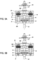
- FIG. 6A represents in perspective and top view yet another variant, which appears in perspective section on the Figure 6B .
- the stop in rotation of the fixing screws 34 is carried out by an elongated bar 90 coupled to the screw head 36.
- the bar 90 is received in two opposite notches 91A and 91B opening into the bore 46.
- the cooperation between the bar 90 and these notches 91A and 91B blocks the corresponding fixing screw 34 in rotation relative to the upper plate 32.
- the bar 90 can for example be metallic.
- the fixing of the bar 90 to the screw head 36 can be carried out by clipping, by welding points, or by forcefully pushing the bar 90 into a housing (not shown) that the screw head 36 carries.
- lower threaded end 35 of the fixing screw 34 can be simply screwed into the tapped hole 38 of the lower plate 31, without counter nut or welding point.
- FIG. 7A represents in perspective and top view yet another variant which is similar to that of the Figures 6A and 6B , except that the bar 90 cooperates with a single notch 91 opening into the bore 46.
- the notch 91 can open onto a side face of the upper plate 32 as shown in the Figure 7A , but as a variant, the notch 91 may not open onto this side face.
- a rotation blocking element 90C which can be used to replace the bar 90.
- This element 90C is of the key type, that is to say it comprises a central washer 90C2 from which a tongue 90C1 extends .
- the tongue 90C1 is received in the notch 91 and thus blocks the corresponding fixing screw 34 in rotation relative to the upper plate 32.
- the central washer 90C2 is housed in the bore 46.
- the fixing of the central washer 90C2 to the screw head 36 can be produced by clipping, by welding points, or by forcefully pressing the element 90C into a housing (not shown) that the screw head 36 carries.
- the element 90C may have two opposite tabs, received respectively in the notches 91A and 91B.
- the element 90D is of the key type, that is to say it comprises a central cup 90D2 from from which a 90D1 tab extends.
- the tongue 90D1 is received in the notch 91 and thus blocks the corresponding fixing screw 34 in rotation relative to the upper plate 32.
- the central cup 90D2 is housed in the bore 46.
- the central cup 90D2 has a flared shape and complementary to the shape of the screw head 36.
- the screw head 36 is received in the central cup 90D2, the central cup 90D2 then being arranged between the screw head 36 and the bottom of the bore 46.
- the fixing of the screw head 36 to the central cup 90D2 can be carried out by clipping, by welding points, or by forcefully pressing the screw head 36 into the flared shape of the central cup 90D2.
- the central cup 90D2 can optionally have a notch 90D3, so that the central cup 90D2 has an overall “C”-shaped shape when viewed from above.
- the notch 90D3 can for example be diametrically opposite the tongue 90D1 relative to the center of the central cup 90D2.
- the central washer 90C2 may also have a notch similar to the notch 90D3, for example diametrically opposite the tongue 90C1.
- compression springs 69 for example helical springs, are engaged on the two fixing screws 34 between the spacer block 33 and the upper plate 32 and maintain the plates 32 and 31 in the spaced position shown on the figure 8 , in a state of rest. More precisely, as elastic elements, the compression springs 69 create a clearance equal to the dimensional difference 40 between the spacer block 33 and the upper plate 32. In response to a pressure force exerted on the upper plate 32, the springs 69 are compressed by gradually erasing this play, up to the abutment position of the lower face 49 of the upper plate 32 against the upper face 48 of the spacer block 33.
- the compression springs 69 are here housed in a stage 19 of large diameter of the bores receiving the fixing screws 34 and bear against a shoulder at the bottom of the stage 19. This shoulder can be provided with a spring seat 69A for receive the support of the compression spring 69. In the stop position, the compression springs 69 are entirely contained in the stage 19.
- the rotation of the fixing screws 34 is stopped by an elongated bar 90 which cooperates with a single notch 91 opening into the bore 46, this notch opening onto a side face of the upper plate 32 as shown on the figure 8 .
- the notch 91 may not open onto this side face.
- the lower threaded end 35 of the fixing screw 34 can be simply screwed into the tapped hole 38 of the lower plate 31, without counter nut or welding point.
- the fixing screws 34 are configured to generate a compression preload on the compression springs 69 in the rest position, so that the upper plate 32 is able to receive moderate loads without sinking. For example a preload of around 1000N is applied, which makes it possible to support the load of a adult man who could walk in line with the anchoring device 20 during the construction of the tank.
- the stiffness of the compression springs 69 is determined as a function of the structure of the tank wall and the operating conditions of the tank so that the upper plate 32 can generally follow the depression of the cover plate 15 of the secondary insulating blocks 7 during the operation of the tank, in particular under the effect of thermal contraction and static and dynamic pressures received by the tank wall 1 in operation. These pressures can in particular lead to creep of the layer of insulating polymer foam 16.
- the compression springs 69 can be positioned differently to perform the same functions.
- the fixing screws 34 can be reversed, with the screw head 36 on the side of the lower plate 31 and then positioning the compression springs 69 between the lower plate 31 and the spacer block 33.
- the compression springs 69 are positioned between the upper plate 32 and the spacer block 33.
- a counter nut 37B preferably unslotted, is screwed onto the lower threaded end 35 of the fixing screw 34.
- the counter nut 37B is received in a groove 92 presented by the lower plate 31 and in which the hole 38, possibly tapped, opens out.
- the groove 92 opens onto the lower face of the lower plate 31.
- the groove 92 has two facing faces with which two distinct faces of the lock nut 37B cooperate. This cooperation blocks the fixing screw 34 from rotating relative to the lower plate 31.
- the counter nut 37B is a square nut.
- the counter nut 37B can also be of another shape as long as it has two distinct faces capable of cooperating with two faces facing the groove 92.
- the counter nut 37B can be of hexagonal shape, two adjacent faces of the hexagon then cooperating with two faces facing the groove 92.
- a stop in rotation of the fixing screws 34 relative to the upper plate 32 is also achieved by making the screw heads 36 integral with the upper plate 32, for example by welding, in particular by spot welding.
- the groove 92 can open onto a side face of the lower plate 31 as shown in the figures 11 and 12 , but as a variant, the groove 92 may not open onto this side face.
- the spacer piece 350 has a blind hole 60 extending in the extension of each fixing screw 34 as will be detailed later.
- the spacer block 33 can be fixed to the lower plate 31, in order to avoid any relative movement between the spacer block 33 and the lower plate 31, in particular in the direction in which the fixing screws 34 extend.
- This fixing of the spacer block 33 to the lower plate 31 can be carried out by screwing and/or by riveting and/or by gluing.
- the spacer block 33 can be fixed to the upper plate 32, for example by screwing and/or by riveting and/or by gluing, in particular when the elastic elements 39 or 69 are positioned between the lower plate 31 and the spacer block 33.
- a layer of polymer foam can be placed on the spacer block 33 facing the upper plate 32 or on the upper plate 32 facing the spacer block 33.
- the Figure 10A represents the anchoring device according to the variant of the figure 8 and having such a layer of polymer foam.
- the layer of polymer foam 68 is fixed to the upper face 48 of the spacer block 33, on either side of the upper end 44 of the anchor rod 22.
- the thickness of the uncompressed polymer foam layer 68 is taken equal to the desired dimensional deviation 40.
- the polymer foam layer 68 when the polymer foam layer 68 is not compressed, it extends between the face 48 of the spacer block 33 and the lower face 49 of the plate 32 and thus defines the dimensional gap 40 between the plates 32 and 31 in their maximum spacing position.
- the layer of polymer foam 68 therefore materializes the desired dimensional difference 40, which facilitates the assembly of the clamping assembly 30.
- the stiffness of the uncompressed polymer foam layer 68 is very small compared to the stiffness of the compression springs 69, such that compression of the polymer foam layer 68 does not significantly interfere with compression of the springs. compression 69.
- the thickness of the uncompressed polymer foam layer 68 is between 2 and 8 mm, so that the polymer foam layer 68 has a thickness between 1 and 6 mm in the abutment position.
- the polymer foam layer 68 can be made from a polyurethane, polyethyl, polypropylene foam or a melamine foam, in particular a melamine foam from the family of foams marketed by the company BASF SE under the name Basotect ® .
- the layer of polymer foam 68 can be fixed to the upper face 48 of the spacer block 33 by gluing or include an adhesive strip, for example.
- the geometry of the polymer foam layer 68 shown on the Figure 10A is only an example.
- the layer of polymer foam 68 also extends to the lateral edges of the spacer block 33, around the bores of the spacer block 33 receiving the compression springs 69, so as not to risk coming into contact with the turns of the compression springs 69.
- the layer of polymer foam 68 can also be placed only around said bores.
- the tank wall 1 could be limited to the secondary insulating barrier 3 and the secondary waterproof membrane 4 to create a simple membrane tank.
- the anchoring device 20 also includes a primary stage.
- the upper plate 32 has a threaded bore 47 in its center, in which is mounted a threaded base of a stud 27 intended for anchoring the primary insulating blocks 11.
- the stud 27 passes through a drilling provided through a metal strake 8 of the secondary waterproof membrane 4.
- the stud 27 has a collar which is welded to its periphery, around the bore, to ensure the sealing of the secondary waterproof membrane 4.
- the primary stage of the anchoring device 20 also comprises a primary support plate 28 which is supported in the direction of the supporting wall 2 on a support zone provided in each of the four adjacent primary insulating blocks 11 so as to retain against the secondary waterproof membrane 4.
- each support zone 29 is formed by an overhanging part of a bottom plate of the primary insulating block 11.
- a nut 29 cooperates with a thread provided at the upper end of the stud 27 so as to ensure the fixing of the primary support plate 28 on the stud 27.
- the anchoring device 20 further comprises a Belleville type elastic washer threaded onto the stud 27 between the nut 28 and the primary support plate 28, which ensures elastic anchoring of the primary insulating blocks 11 on the secondary waterproof membrane 4.
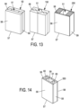
- FIG. 13 illustrates several embodiments of a spacer piece 50, 150 or 250 of the anchoring device 20, which each has a central through housing 51 to allow the anchoring rod 22 to pass, an upper end surface 56 for receive the support of the lower plate 31 and a lower end surface 57 to exert support on the secondary insulating block.
- the spacer piece 50, 150 or 250 is for example made of plywood to limit the thermal bridge.
- the spacer piece 50, 150 or 250 preferably has a section identical to the lower plate 3, of rectangular shape in the embodiments shown. It can be formed from a small number of elongated parts having simple shapes, rigidly assembled together, for example by stapling, screwing and/or gluing.
- the central through housing 51 is filled with a thermal insulator around the anchoring rod 22, for example glass wool, wadding, expanded polystyrene or polyurethane foam.
- the spacer piece 50 or 250 is formed of two flat rectangular plates 58 forming the main faces of the spacer piece and two battens 59 arranged between the two flat rectangular plates along the edges thereof. Each of the four parts thus forms a wall of the central through housing 51, which has a square or rectangular section.
- the spacer piece 150 is formed of four identical elongated profiled pieces having a section in the shape of a rectangular trapezoid, an inclined side of which forms a respective wall of the central through housing 51, which has a diamond-shaped section. To limit the thermal bridge, longitudinal cells are provided on either side of the central through housing 51 and also filled with an insulating material.
- FIG. 14 illustrates yet another embodiment of a spacer part 350.
- This spacer part 350 is identical to the spacer part 250 except that each cleat 59 has a blind hole 60, each blind hole 60 being intended to come in the extension of a fixing screw 34 so as to be able to receive a part of this fixing screw 34.
- the spacer piece 50 can also have such blind holes 60.
- the longitudinal cells provided on either side of the central through housing 51 can be only partially filled with the insulating material, so that the insulating material and the cells longitudinal together provide blind holes similar to the blind holes 60.
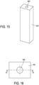
- the thermal insulating block 451 has an exterior shape complementary to the central through housing 51, here a parallelepiped exterior shape.
- the thermal insulating block 451 is here made of a thermally insulating polymer foam.
- the polymer foam can be low density, that is to say a density between 10 kg/m 3 and 60 kg/m 3 , more particularly between 10 kg/m 3 and 30 kg/m 3 .
- the polymer foam can be a polyurethane foam or a melamine foam, in particular a melamine foam from the family of foams marketed by the company BASF SE under the name Basotect ® .
- the polymer foam can optionally be reinforced with fibers, for example glass fibers.
- the thermal insulating block 451 has a through hole 452.
- the through hole 452 is intended to receive the anchor rod 22 when the spacer piece is placed under the clamping assembly 30 as described previously.
- the through hole 452 has a section which widens going from the upper end of the anchor rod 22 towards the lower end of the anchor rod 22. In particular, this can be obtained by giving the hole crossing 452 a frustoconical section as shown on the Figure 14 . This widening of the section going towards the lower end of the anchor rod 22 makes it easier to install the spacer piece around the anchor rod 22, it being indicated that this installation is carried out when the anchor rod anchor 22 is already fixed to the supporting wall 2 by the socket 23 and the nut 18.
- the through hole 452 can also have a section which widens going from the lower end of the anchor rod 22 towards the upper end of the anchor rod. anchoring 22. In particular, this can be obtained by giving the through hole a frustoconical section.
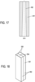
- FIG 18 illustrates another embodiment of a thermal insulating block 551 which can be received in the central through housing 51.
- the thermal insulating block 551 has an exterior shape complementary to the central through housing 51, here a parallelepiped exterior shape.
- the thermal insulation block 551 is here made of glass wool. It may possibly consist of two sub-blocks 552 of glass wool joined together.
- the thermal insulating block 551 surrounds the anchor rod 22 (not shown on the Figure 15 ) when the spacer piece is placed under the clamping assembly 30 as described previously. To do this, the thermal insulating block 551 can have in its thickness a notch 554 which extends parallel to the anchor rod 22.
- the notch 554 allows the anchor rod 22 to pass through the block thermal insulator 551 while allowing the elastic return of the glass wool to grip the anchoring rod 22 once it has passed through the thermal insulating block 551.
- the thermal insulating block 551 can also be made in the same way with cellulose or polyester wadding.
- sheets 555 can be arranged on two opposite faces of the thermal insulating block 551, more particularly the two largest faces of the thermal insulating block 551 which face the two largest faces of the central through housing 51.
- the sheets 555 can be made of glass fabric, kraft paper or even a polymer such as PVC.
- the sheets 555 make it easier to slide the thermal insulating block 551 on the faces of the central through housing 51 when the thermal insulating block 551 is inserted into the central through housing 51.
- only one of the sheets 555 can be present, and/or additional sheets not shown can be added to the faces of the thermal insulating block 551 which are not covered by the sheets 555.
- FIG. 19 We represented on the figures 19 and 20 yet another variation of a spacer piece together with the clamping assembly 30, the Figure 19 being a sectional view and the Figure 20 being a partial perspective view from above the spacer piece.
- a counter nut 37B preferably unslotted, is screwed onto the lower threaded end 35 of the fixing screw 34.
- the counter nut 37B is received in a groove 660 which the spacer part 650 presents.
- the spacer part 650 is here formed, like the spacer piece 250, of two flat rectangular plates 58 forming the main faces of the spacer piece 650 and two battens 59 arranged between the two flat rectangular plates 58 along the edges thereof.
- a groove 660 is formed in each of the two cleats 59.
- the groove 660 has two facing faces with which two distinct faces of the locknut 37B cooperate. This cooperation blocks the fixing screw 34 from rotating relative to the lower plate 31.
- the lock nut 37B is a square nut.
- the lock nut 37B can also be of another shape as long as it has two distinct faces capable of cooperating with two faces facing the groove 660.
- the lock nut 37B can be of hexagonal shape, two opposite faces of the hexagon then cooperating with two faces facing the groove 660.
- a stop in rotation of the fixing screws 34 relative to the upper plate 32 is also achieved by making the screw heads 36 integral with the upper plate 32, for example by welding, in particular by spot welding.
- the clamping assembly 30 is in the spaced position corresponding to the maximum spacing when the tank is empty and at room temperature, that is to say under the conditions of its initial construction. In this state, the position of the upper plate 32 is adjusted to be aligned with the cover plate 15, so as to provide a uniform support surface for the secondary waterproof membrane 4.
- Thermal contractions are not identical in all materials and the layers of insulating polymer foam 16 tend to contract more than the plywood constituting the spacer piece 50 and the spacer block 33.
- the pressure loads are different depending on the position of the tank wall at the bottom, on the ceiling or on the sides. All walls receive at least the operating pressure of the vapor phase, which is for example 2kPa or 5kPa (20 or 50 mbar).
- the stiffness of the elastic elements 39 or 69 can be dimensioned so that, after cooling and under the operating pressure of the vapor phase, the elastic compression of the elastic elements 39 or 69 allows an additional lowering of the upper plate 32 which is greater than or equal to the additional contraction and creep of the secondary insulating blocks 7 relative to the thermal contraction of the anchoring device 20.
- This additional contraction and creep of the secondary insulating blocks 7 is for example approximately 1mm under pressure vapor phase service.
- the upper plate 32 follows the level of the cover plates 15 and does not risk generating a protruding zone capable of shearing the secondary waterproof membrane 6.
- the elastic elements 39 or 69 increase the flexibility of the anchoring device 20 and thus limit the risk of locally forming a hard point or a protruding zone which could accelerate the aging of the secondary waterproof membrane 6.
- the total stiffness of the elastic member acting between the two plates is less than the equivalent stiffness of the thermally insulating barrier at the service temperature in the immediate vicinity of the device. 'anchoring.
- it is the layer of insulating polymer foam 16 which controls the stiffness of the thermally insulating barrier.
- the total stiffness of the elastic elements 39 or 69 is approximately 1880N/mm while the stiffness in the direction of thickness of the tank wall is equivalent to a spring made of insulating polymer foam 16 having an equal section to that of the upper plate is approximately 1920N/mm, i.e. a stiffness ratio equal to 0.98. More generally, this ratio could be chosen between 0.3 and 1.
- the structure of the secondary insulating block 7 is described above by way of example. Also, in another embodiment, the secondary insulating blocks 7 are likely to have another general structure, for example that described in the document WO-A-2012127141 .
- the secondary insulating blocks 7 are then produced in the form of a box comprising a bottom plate, a cover plate and supporting sails extending, in the direction of thickness of the tank wall 1, between the bottom plate and the cover plate and delimiting a plurality of compartments filled with an insulating filling, such as perlite, glass wool or rock wool.
- the layer of insulating polymer foam is here divided into two lower and upper layers 16b and 16a separated by an intermediate plate 10, for example made of plywood, glued to them.
- the length of the top layer 16a is smaller than the length of the lower layer 16b and reveals a rim 10a at two longitudinal ends of the intermediate plate 10.
- a rigid pillar 17 extends in the thickness direction of the lower layer 16b between the intermediate plate 10 and the bottom plate 114, in recesses provided at the four corners of the lower layer 16b.
- the rigid pillar 17 is partially perpendicular to the rim 10a to take up the tightening force of the anchoring device 20, the lower complaint 31 of which can here be applied directly to the rim 10a. Further details of secondary insulator block 107 can be found in the publication WO-A-2014096600 .
- the primary insulating block 11 can be produced in different ways, for example in the form of a layer of insulating polymer foam sandwiched between a bottom plate and a cover plate like the secondary insulating block 7.
- the bottom plate then has grooves intended to receive the raised edges of the strakes 8 of the secondary sealing membrane 4.
- the cover plate also has grooves for receiving welding supports.
- the structure of the primary insulating panel 11 is described above by way of example. Also, in another embodiment, the primary insulating panels 22 are likely to have another general structure, for example that described in the document WO-A-2012127141 .
- the technique described above for producing a tank wall with a single or two watertight membranes can also be used in different types of tanks, for example to constitute a double membrane tank for liquefied natural gas (LNG) in a land installation or in a floating structure such as an LNG ship or other.
- LNG liquefied natural gas
- a cutaway view of an LNG ship 70 shows a watertight and insulated tank 71 of generally prismatic shape mounted in the double hull 72 of the ship.
- the wall of the tank 71 comprises a primary waterproof barrier intended to be in contact with the LNG contained in the tank, a secondary waterproof barrier arranged between the primary waterproof barrier and the double hull 72 of the ship, and two insulating barriers arranged respectively between the primary waterproof barrier and the secondary waterproof barrier and between the secondary waterproof barrier and the double hull 72.
- loading/unloading pipes 73 arranged on the upper deck of the ship can be connected, by means of appropriate connectors, to a maritime or port terminal to transfer a cargo of LNG from or to the tank 71.
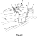
- FIG. 23 represents an example of a maritime terminal comprising a loading and unloading station 75, an underwater pipe 76 and an onshore installation 77.
- the loading and unloading station 75 is a fixed off-shore installation comprising a movable arm 74 and a tower 78 which supports the mobile arm 74.
- the mobile arm 74 carries a bundle of insulated flexible pipes 79 which can connect to the loading/unloading pipes 73.
- the adjustable mobile arm 74 adapts to all LNG carrier templates.
- a connection pipe not shown extends inside the tower 78.
- the loading and unloading station 75 allows the loading and unloading of the LNG tanker 70 from or to the onshore installation 77.
- the underwater pipe 76 allows the transfer of the liquefied gas between the loading or unloading station 75 and the onshore installation 77 over a long distance, for example 5 km, which makes it possible to keep the LNG ship 70 at a long distance from the coast during loading and unloading operations.
- pumps on board the ship 70 and/or pumps fitted to the on-shore installation 77 and/or pumps fitted to the loading and unloading station 75 are used.
Landscapes
- Engineering & Computer Science (AREA)
- Mechanical Engineering (AREA)
- Physics & Mathematics (AREA)
- Thermal Sciences (AREA)
- General Engineering & Computer Science (AREA)
- Chemical & Material Sciences (AREA)
- Combustion & Propulsion (AREA)
- Ocean & Marine Engineering (AREA)
- Filling Or Discharging Of Gas Storage Vessels (AREA)
- Devices Affording Protection Of Roads Or Walls For Sound Insulation (AREA)
Claims (27)
- Verankerungsvorrichtung (20) zum Halten von Isolierblöcken an einer Trägerwand, wobei die Verankerungsvorrichtung (20) umfasst:eine Klemmanordnung (30) mit einer unteren Platte (31), einer oberen Platte (32) parallel zur unteren Platte, ein Verbindungsorgan (34), welches die untere Platte mit der oberen Platte verbindet, und einem Abstandshalter, der zwischen der unteren Platte und der oberen Platte angeordnet ist, wobei der Abstandshalter ein Anschlagstück umfasst, das einen Mindestabstand zwischen der unteren Platte und der oberen Platte in einer Anschlagposition der unteren und oberen Platte gegen das Anschlagstück definiert, wobei das Anschlagstück einen starren Teil (33) umfasst, undeine Ankerstange (22), die von der Klemmanordnung senkrecht zur unteren Platte (31) vorsteht, wobei die Ankerstange ein unteres Ende, das dazu bestimmt ist, an einer Trägerwand (2) befestigt zu werden, und ein oberes Ende aufweist, das dem unteren Ende gegenüberliegt und mit der unteren Platte (31) gekoppelt ist, um eine Zugkraft auf die untere Platte in Richtung auf das untere Ende ausüben zu können,wobei die Verankerungsvorrichtung (20) dadurch gekennzeichnet ist, dass der Abstandhalter weiterhin ein elastisch komprimierbares Organ (39, 69) umfasst, das dazu dient, die untere Platte und die obere Platte (32) in einer beabstandeten Position zu halten, wobei das Verbindungsorgan einen maximalen Abstand zwischen der unteren Platte und der oberen Platte in der beabstandeten Position festlegt, wobei maximale Abstand größer ist als der minimale Abstand, wobei das elastisch komprimierbare Organ (39, 69) ist so konfiguriert, dass es sich elastisch bis zu der Position komprimiert, in der die untere und die obere Platte (31, 32) an das Anschlagstück anstoßen, in Reaktion auf eine Kraft, die dazu dient, die obere Platte näher an die untere Platte heranzuführen.
- Verankerungsvorrichtung gemäß Anspruch 1, wobei das Verbindungsorgan mindesten eine Verbindungsstange (34) umfasst, welche parallel zur unteren und oberen Platte verläuft und sich durch eine im Anschlagstück angeordnete Aussparung erstreckt, wobei mindestens eine von er unteren Platte und der oberen Platte verschiebbar zur Verbindungsstange angeordnet ist, um bis zur Anschlagposition gleiten zu können.
- Verankerungsvorrichtung gemäß Anspruch 1, wobei das Verbindungsorgan witerhin ein erstes Arretierelement (36, 37 A, 368) umfasst, das mit einem ersten Ende der Verbindungsstange gekoppelt ist, um die obere Platte (32) in Bezug auf die Verbindungsstange in der beabstandeten Position in Längsrichtung zu arretieren.
- Verankerungsvorrichtung gemäß Anspruch 1, wobei das erste Arretierelement eine Mutter (36B) aufweist, welche auf das erste Ende der Verbindungsstange (34) geschraubt und mit diesem verschweißt ist, und wobei ein zweites Ende der Verbindungsstange (34) fest mit der unteren Platte (31) verbunden ist.
- Verankerungsvorrichtung gemäß Anspruch 3, wobei das Verbindungsorgan weiterhin ein Drehblockierungselement (90, 90C) umfasst, das mit dem ersten Arretierelement (36) gekoppelt ist, wobei ein Teil des Drehblockierungselements (90, 90C) in einer Aussparung (91, 91A, 918) der oberen Platte (32) liegt, um die Verbindungsstange (34) in Drehung zu blockieren.
- Verankerungsvorrichtung gemäß Anspruch 2 oder 3, wobei das Verbindungsorgan weiterhin ein zweites Arretierelement (37, 38, 36A, 38A, 37B) umfasst, das mit einem zweiten Ende der Verbindungsstange gekoppelt ist, um die untere Platte (31) in Bezug auf die Verbindungsstange in der beabstandeten Position in Längsrichtung zu arretieren.
- Verankerungsvorrichtung gemäß den Ansprüchen 3 und 6, bei der das erste Arretierelement eine Mutter (37 A) umfasst, die auf das erste Ende der Verbindungsstange (34) geschraubt und daran angeschweißt ist, und bei der das zweite Arretierelement (36 A) fest mit der unteren Platte (31) verbunden ist.
- Verankerungsvorrichtung gemäß den Ansprüchen 3 und 6, bei der das zweite Arretierelement (37B) in einer Nut (92) der unteren Platte aufgenommen ist, wobei die Nut (92) zwei einander gegenüberliegende Flächen aufweist, mit denen zwei verschiedene Flächen des zweiten Arretierelements (378) zusammenwirken, um die Verbindungsstange (34) in Drehung zu blockieren, und wobei das erste Arretierelement (36) fest mit der oberen Platte (32) verbunden ist.
- Verankerungsvorrichtung gemäß den Ansprüchen 3 und 6, weiterhin umfassend ein Abstandsstück (650), das unter der unteren Platte angeordnet ist und eine zentrale Aufnahme (51) aufweist, durch die die Ankerstange verläuft, wobei das Abstandsstück eine obere Fläche (56), die so gestaltet ist, dass sie sich gegen die untere Platte der Klemmanordnung abstützt, und eine untere Fläche (57), die dazu bestimmt ist, sich gegen einen Isolierblock abzustützen, aufweist, und wobei das zweite Arretierelement (37B) in einer Nut (660) des Abstandstückes (650) aufgenommen wird, wobei die Nut zwei gegenüberliegende Flächen aufweist, mit denen zwei gegenüberliegende Flächen des zweiten Arretierelements (37B) zusammenwirken, um die Verbindungsstange (34) in Drehung zu blockieren, und wobei das erste Arretierelement (36) fest mit der oberen Platine (32) verbunden ist.
- Verankerungsvorrichtung gemäß einem der Ansprüche 2 bis 9, wobei das elastisch komprimierbare Organ (39, 69) mit der Verbindungsstange in Eingriff ist.
- Verankerungsvorrichtung nach einem der Ansprüche 2 bis 10, bei der sich das elastisch komprimierbare Organ (39, 69) gegen das Anschlagstück abstützt.
- Verankerungsvorrichtung gemäß Anspruch 11, wobei die Aussparung im Anschlagstück eine Ebene (19) aufweist, in der das elastisch komprimierbare Organ (39, 69) angeordnet ist.
- Verankerungsvorrichtung gemäß einem der Ansprüche 1 bis 12, wobei das elastisch komprimierbare Organ (39) einen Stapel elastischer Unterlegscheiben umfasst.
- Verankerungsvorrichtung gemäß einem der Ansprüche 1 bis 13, wobei das elastisch komprimierbare Organ (69) eine Schraubenfeder umfasst.
- Verankerungsvorrichtung gemäß einem der Ansprüche 1 bis 14, wobei die elastische Auslenkung zwischen der beabstandeten Position und der Anschlagposition der oberen und unteren Platten (31, 32) zwischen 1 und 8 mm beträgt; vorzugsweise zwischen 4 und 7 mm.
- Verankerungsvorrichtung gemäß einem der Ansprüche 1 bis 15, wobei die untere Platte (31) eine zentrale Bohrung (41) aufweist, die vom oberen Ende der Ankerstange (22) durchdrungen wird, wobei die Verankerungsvorrichtung eine Mutter (42) umfasst, die mit einem Gewindeabschnitt des oberen Endes der Ankerstange zusammenwirkt, und eine oder mehrere elastische Unterlegscheiben (43), die auf das obere Ende der Ankerstange zwischen der Mutter und der unteren Platte aufgesteckt sind, so dass eine elastische Kraft auf die untere Platte in Richtung des unteren Endes der Ankerstange ausgeübt werden kann.
- Verankerungsvorrichtung gemäß Anspruch 16 in Verbindung mit Anspruch 2, wobei die Klemmanordnung (30) mindestens zwei Verbindungsstangen (34) aufweist, die symmetrisch zu der zentralen Bohrung (41) angeordnet sind.
- Verankerungsvorrichtung gemäß einem der Ansprüche 1 bis 17, umfassend Abstandsstück (50, 150, 250, 350, 650), das unter der unteren Platte angeordnet ist und eine zentrale Aufnahme (51) aufweist, die von der Ankerstange durchquert wird, wobei das Abstandsstück eine obere Fläche (56), die so gestaltet ist, dass sie sich gegen die untere Platte der Spanneinheit abstützt, und eine untere Fläche (57), die dazu bestimmt ist, sich gegen einen Isolierblock abzustützen aufweist.
- Verankerungsvorrichtung gemäß einem der Ansprüche 1 bis 18, umfassend eine Hülse (23), die auf das untere Ende der Ankerstange aufgesetzt ist und dazu bestimmt ist, an der tragenden Wand (2) befestigt zu sein, wobei die Hülse eine Aufnahme aufweist, die das untere Ende der Ankerstange (22) aufnimmt, um eine Gelenkverbindung zu bilden.
- Verankerungsvorrichtung gemäß einem der Ansprüche 1 bis 19, wobei das Anschlagstück an einer der unteren Platte (31) oder der oberen Platte (32) befestigt ist.
- Dichtes und wärmeisolierendes Gefäß zur Lagerung einer Flüssigkeit, umfassend eine tragende Wand, Verankerungsvorrichtungen (20), die an der Trägerwand (2) befestigt sind, und eine Gefäßwand (1), die mit Hilfe der Verankerungsvorrichtungen an der Trägerwand verankert ist, wobei die Gefäßwand (1) in einer Dickenrichtung von der Außenseite zum Inneren des Gefäßes aufeinanderfolgend eine isolierende Sperre (3) und eine Dichtungsmembran (4) aufweist, die gegen die isolierende Sperre (3) anliegt,wobei die isolierende Sperre (3) parallelepipedisch geformte Isolierblöcke (7) umfasst, die nebeneinander auf der Trägerwand (2) angeordnet sind, wobei ein Isolierblock eine Deckelplatte aufweist, die eine Stützfläche für die Dichtungsmembran (4) definiert;wobei mindestens eine der genannten Verankerungsvorrichtungen gemäß einem der Ansprüche 1 bis 20 ist, wobei das untere Ende der Ankerstange (22) an der Trägerwand zwischen einer Vielzahl von Isolierblöcken (7) befestigt ist, wobei die untere Platte (31) der Ankervorrichtung mit der Vielzahl von Isolierblöcken (7, 107) zusammenwirkt, um die Vielzahl von Isolierblöcken in Richtung der Trägerwand (2) zu drücken.
- Gefäß gemäß einem der Ansprüche 21, wobei das elastisch komprimierbare Organ (39, 69) so konfiguriert ist, dass es die untere und die obere Platte in einem leeren Zustand des Gefäßes in der beabstandeten Position hält, wobei die obere Platte (32) der Verankerungsvorrichtung in der beabstandeten Position mit den Deckelplatten der Vielzahl von Isolierblöcken auf einer Linie ist, um die Dichtungsmembran (4) abzustützen.
- Gefäß gemäß einem der Ansprüche 21 oder 22, wobei ein Isolierblock umfasst eine Bodenplatte (14) parallel zu und beabstandet von der Deckelplatte (15), einen faserverstärkten Polymerschaumblock (16), der zwischen der Deckelplatte und einer Bodenplatte angeordnet ist, und wobei die untere Platte der Verankerungsvorrichtung direkt oder indirekt mit der Bodenplatte (14) zusammenwirkt, ohne Druck auf den Polymerschaumblock (16) auszuüben.
- Gefäß gemäß einem der Ansprüche 21 oder 22, wobei ein Isolierblock (107) umfasst eine Bodenplatte (114), und aufeinanderfolgend eine Zwischenplatte (10) und eine Deckelplatte (115), die parallel zur Bodenplatte und voneinander beabstandet sind, und zwei Blöcke aus faserverstärktem Polymerschaum (16a, 16b), die jeweils zwischen der Deckelplatte und der Zwischenplatte und zwischen der Zwischenplatte und der Bodenplatte angeordnet sind, wobei die untere Platte (31) der Verankerungsvorrichtung an einem Eckbereich direkt mit der Zwischenplatte (10) zusammenwirkt.
- Gefäß gemäß einem der Ansprüche 21 oder 22, wobei ein Verhältnis zwischen der Steifigkeit des elastisch komprimierbaren Organs und einer Steifigkeit der Gefäßwand in der Dickenrichtung zwischen 0,3 und 1 liegt, wobei die Gefäßwand einer Feder entspricht, die aus faserverstärktem Polymerschaum besteht, und einen Querschnitt gleich dem der oberen Platte aufweist.
- Gefäß gemäß einem der Ansprüche 21 bis 25, wobei die wärmeisolierende Sperre eine sekundäre wärmeisolierende Sperre (3) ist, die Isolierblöcke sekundäre Isolierblöcke (7) sind und die Dichtungsmembran eine sekundäre Dichtungsmembran (4) ist, wobei die Gefäßwand weiterhin eine primäre wärmeisolierende Sperre (5), die an der sekundären Dichtungsmembran (4) anliegt, und eine primäre Dichtungsmembran (6), die an der primären wärmeisolierenden Sperre (5) anliegt und dazu bestimmt ist, mit der in dem Gefäß enthaltenen Flüssigkeit in Kontakt zu sein, aufweist; wobei die primäre wärmeisolierende Sperre (5) primäre Isolierblöcke (11) aufweist, die jeweils auf einem der sekundären Isolierblöcke (7) aufliegen,
wobei die Klemmanordnung (30) ein sekundäres Klemmorgan bildet, das dazu bestimmt ist, mit der sekundären isolierenden Sperre zusammenzuwirken, wobei die obere Platte (32) eine zentrale Aussparung (47) aufweist, in die ein Bolzen (27) eingeschraubt ist, der von der Klemmanordnung entgegengesetzt zur Ankerstange vorsteht, wobei der Bolzen (27) ein primäres Klemmorgan (28) trägt, das dazu bestimmt ist, mit der primären isolierenden Sperre (5) zusammenzuwirken, und wobei der Bolzen (27) die sekundäre Dichtungsmembran (4) abdichtend durchdringt und das primäre Klemmelement in Richtung der Trägerwand (2) gegen eine Vielzahl von primären Isolierblöcken (11), die der Vielzahl von sekundären Isolierblöcken überlagert sind, anliegend gehalten wird, um die Vielzahl von primären Isolierblöcken in Richtung der Trägerwand (2) zu halten. - Schiff (79) zum Transport einer Flüssigkeit, wobei das Schiff eine Doppelhülle (72) und ein in der Doppelhülle angeordnetes Gefäß (71) gemäß einem der Ansprüche 21 bis 26 umfasst.
Applications Claiming Priority (4)
| Application Number | Priority Date | Filing Date | Title |
|---|---|---|---|
| FR2005545A FR3110951B1 (fr) | 2020-05-26 | 2020-05-26 | Dispositif d’ancrage destine a retenir des blocs isolants |
| FR2007557A FR3110950B1 (fr) | 2020-05-26 | 2020-07-17 | Dispositif d’ancrage destine a retenir des blocs isolants |
| FR2101660A FR3110953B1 (fr) | 2020-05-26 | 2021-02-19 | Dispositif d’ancrage destine a retenir des blocs isolants |
| PCT/EP2021/063860 WO2021239712A1 (fr) | 2020-05-26 | 2021-05-25 | Dispositif d'ancrage destine a retenir des blocs isolants |
Publications (2)
| Publication Number | Publication Date |
|---|---|
| EP4158237A1 EP4158237A1 (de) | 2023-04-05 |
| EP4158237B1 true EP4158237B1 (de) | 2024-06-19 |
Family
ID=72178768
Family Applications (1)
| Application Number | Title | Priority Date | Filing Date |
|---|---|---|---|
| EP21728878.6A Active EP4158237B1 (de) | 2020-05-26 | 2021-05-25 | Verankerungsvorrichtung zum halten von isolierblöcken |
Country Status (9)
| Country | Link |
|---|---|
| EP (1) | EP4158237B1 (de) |
| JP (1) | JP7553606B2 (de) |
| KR (1) | KR102450352B1 (de) |
| CN (1) | CN114008374B (de) |
| DK (1) | DK4158237T3 (de) |
| ES (1) | ES2988308T3 (de) |
| FR (4) | FR3110951B1 (de) |
| PT (1) | PT4158237T (de) |
| WO (1) | WO2021239712A1 (de) |
Families Citing this family (16)
| Publication number | Priority date | Publication date | Assignee | Title |
|---|---|---|---|---|
| FR3128003B1 (fr) * | 2021-10-08 | 2023-09-22 | Gaztransport Et Technigaz | Dispositif d’ancrage destiné à retenir des blocs isolants |
| FR3135773B1 (fr) | 2022-05-23 | 2024-11-15 | Gaztransport Et Technigaz | Cuve etanche et thermiquement isolante integree dans une structure porteuse |
| CN114962983B (zh) * | 2022-06-29 | 2024-03-08 | 中太能源科技(上海)有限公司 | 用于储存液化气体的储存容器 |
| CN114962984B (zh) * | 2022-06-29 | 2024-02-02 | 中太能源科技(上海)有限公司 | 用于储存液化气体的储存容器及其装配方法 |
| CN114811410B (zh) * | 2022-06-29 | 2022-09-30 | 中太海事技术(上海)有限公司 | 用于运输设备尤其是船舶等海洋装备的液化气体储存舱 |
| FR3143096B1 (fr) * | 2022-12-09 | 2024-11-22 | Gaztransport Et Technigaz | Dispositif d’ancrage pour un bloc thermiquement isolant |
| FR3143098B1 (fr) | 2022-12-09 | 2024-11-08 | Gaztransport Et Technigaz | Dispositif d’ancrage destiné à retenir des blocs isolants, et cuve étanche et thermiquement isolante comprenant ce dispositif d’ancrage |
| FR3149948B1 (fr) | 2023-06-15 | 2025-06-20 | Gaztransport Et Technigaz | Cuve étanche et thermiquement isolante comportant une paroi de cuve non-horizontale, et procédé d’assemblage de cette paroi de cuve |
| FR3149947B1 (fr) | 2023-06-15 | 2025-05-02 | Gaztransport Et Technigaz | Caisson calorifuge pour une cuve étanche et thermiquement isolante |
| KR102717674B1 (ko) * | 2023-07-13 | 2024-10-15 | 한화오션 주식회사 | 화물창용 단열 패널 및 단열박스를 고정하는 고정모듈 |
| FR3152302B1 (fr) | 2023-08-24 | 2026-04-17 | Gaztransport Et Technigaz | Bloc d’espacement pour un dispositif d’ancrage destine a retenir des blocs isolants |
| CN117028827A (zh) * | 2023-10-09 | 2023-11-10 | 中太海碳(上海)环保科技有限公司 | 低温薄膜储存容器的固定模块及低温薄膜储存容器 |
| CN117068326B (zh) * | 2023-10-13 | 2024-02-09 | 沪东中华造船(集团)有限公司 | 一种薄膜型围护系统 |
| CN117068325B (zh) * | 2023-10-13 | 2024-02-09 | 沪东中华造船(集团)有限公司 | 一种薄膜型围护系统绝缘模块受冷变形自适应调整方法 |
| CN117048799B (zh) * | 2023-10-13 | 2024-02-09 | 沪东中华造船(集团)有限公司 | 一种薄膜型围护系统的建造方法 |
| CN117818821B (zh) * | 2024-03-06 | 2024-06-11 | 沪东中华造船(集团)有限公司 | 一种低温液货存储运输用薄膜型围护系统 |
Family Cites Families (12)
| Publication number | Priority date | Publication date | Assignee | Title |
|---|---|---|---|---|
| FR2724623B1 (fr) | 1994-09-20 | 1997-01-10 | Gaztransport Et Technigaz | Cuve etanche et thermiquement isolante perfectionnee integree dans une structure porteuse |
| FR2798902B1 (fr) | 1999-09-29 | 2001-11-23 | Gaz Transport & Technigaz | Cuve etanche et thermiquement isolante integree dans une structure porteuse de navire et procede de fabrication de caissons isolants destines a etre utilises dans cette cuve |
| FR2973097B1 (fr) | 2011-03-23 | 2013-04-12 | Gaztransp Et Technigaz | Element calorifuge pour paroi de cuve etanche et thermiquement isolante |
| FR3000042B1 (fr) | 2012-12-21 | 2015-01-23 | Gaztransp Et Technigaz | Cuve etanche et thermiquement isolante |
| FR3042253B1 (fr) | 2015-10-13 | 2018-05-18 | Gaztransport Et Technigaz | Cuve etanche et thermiquement isolante |
| KR101884761B1 (ko) * | 2016-10-27 | 2018-08-02 | 대우조선해양 주식회사 | 화물창의 멤브레인 타입 단열박스 및 그의 인서트 너트 내장형 고정장치 |
| FR3064042B1 (fr) * | 2017-03-15 | 2021-10-22 | Gaztransport Et Technigaz | Cuve etanche et thermiquement isolante comportant un bouchon isolant de renfort |
| WO2019077253A1 (fr) | 2017-10-20 | 2019-04-25 | Gaztransport Et Technigaz | Cuve etanche et thermiquement isolante a plusieurs zones |
| FR3073600B1 (fr) * | 2017-11-13 | 2019-12-06 | Gaztransport Et Technigaz | Procede de fabrication d'une barriere d'isolation thermique d'une paroi d'une cuve et barriere d'isolation thermique ainsi obtenue |
| FR3074560B1 (fr) | 2017-12-04 | 2021-06-04 | Gaztransport Et Technigaz | Cuve etanche et thermiquement isolante |
| FR3082274B1 (fr) * | 2018-06-06 | 2021-11-19 | Gaztransport Et Technigaz | Cuve etanche et thermiquement isolante |
| FR3102228B1 (fr) * | 2019-10-18 | 2021-09-10 | Gaztransport Et Technigaz | Cuve étanche et thermiquement isolante |
-
2020
- 2020-05-26 FR FR2005545A patent/FR3110951B1/fr active Active
- 2020-07-17 FR FR2007557A patent/FR3110950B1/fr active Active
- 2020-07-17 FR FR2007559A patent/FR3110949B1/fr active Active
-
2021
- 2021-02-19 FR FR2101660A patent/FR3110953B1/fr active Active
- 2021-05-25 ES ES21728878T patent/ES2988308T3/es active Active
- 2021-05-25 JP JP2022572479A patent/JP7553606B2/ja active Active
- 2021-05-25 KR KR1020217034764A patent/KR102450352B1/ko active Active
- 2021-05-25 EP EP21728878.6A patent/EP4158237B1/de active Active
- 2021-05-25 WO PCT/EP2021/063860 patent/WO2021239712A1/fr not_active Ceased
- 2021-05-25 DK DK21728878.6T patent/DK4158237T3/da active
- 2021-05-25 PT PT217288786T patent/PT4158237T/pt unknown
- 2021-05-25 CN CN202180003295.6A patent/CN114008374B/zh active Active
Also Published As
| Publication number | Publication date |
|---|---|
| FR3110950A1 (fr) | 2021-12-03 |
| FR3110951B1 (fr) | 2022-05-06 |
| FR3110949A1 (fr) | 2021-12-03 |
| CN114008374B (zh) | 2023-01-06 |
| JP7553606B2 (ja) | 2024-09-18 |
| FR3110953A1 (fr) | 2021-12-03 |
| EP4158237A1 (de) | 2023-04-05 |
| PT4158237T (pt) | 2024-08-06 |
| DK4158237T3 (da) | 2024-09-09 |
| FR3110951A1 (fr) | 2021-12-03 |
| CN114008374A (zh) | 2022-02-01 |
| FR3110949B1 (fr) | 2022-09-09 |
| JP2023527011A (ja) | 2023-06-26 |
| KR20210149093A (ko) | 2021-12-08 |
| WO2021239712A1 (fr) | 2021-12-02 |
| KR102450352B1 (ko) | 2022-10-05 |
| FR3110950B1 (fr) | 2022-05-06 |
| ES2988308T3 (es) | 2024-11-20 |
| FR3110953B1 (fr) | 2022-06-24 |
Similar Documents
| Publication | Publication Date | Title |
|---|---|---|
| EP4158237B1 (de) | Verankerungsvorrichtung zum halten von isolierblöcken | |
| EP3803187B1 (de) | Wärmeisolierender abgedichteter tank | |
| EP2739895B1 (de) | Abgedichteter wärmeisolierender behälter | |
| WO2019110894A1 (fr) | Cuve étanche et thermiquement isolante | |
| WO2019012236A1 (fr) | Cuve etanche et thermiquement isolante | |
| EP3710742B1 (de) | Verfahren zur herstellung einer wärmedämmbarriere für eine wand eines gefässes und dadurch hergestellte wärmedämmbarriere | |
| WO2019012237A1 (fr) | Cuve etanche et thermiquement isolante a bande de support incurvee | |
| FR3105342A1 (fr) | Barrière thermiquement isolante pour une paroi d’une cuve | |
| EP2984381A1 (de) | Isolierblock zur herstellung einer versiegelten und isolierten behälterwand | |
| FR3128003A1 (fr) | Dispositif d’ancrage destiné à retenir des blocs isolants | |
| WO2023001678A1 (fr) | Installation de stockage pour gaz liquéfié | |
| FR3073270A1 (fr) | Cuve etanche et thermiquement isolante comportant des dispositifs d'ancrage des panneaux isolants primaires sur des panneaux isolants secondaires | |
| EP3596383B1 (de) | Wärmeisolierender abgedichteter behälter mit verstärkungsisolierstopfen | |
| EP3807567A1 (de) | Abgedichteter und wärmeisolierender tank | |
| EP4399434A1 (de) | Lagereinrichtung für flüssiggas | |
| FR3121730A1 (fr) | Dispositif d’ancrage destiné à retenir des blocs isolants | |
| WO2022074226A1 (fr) | Cuve étanche et thermiquement isolante | |
| WO2023067026A1 (fr) | Cuve étanche et thermiquement isolante | |
| WO2022100975A1 (fr) | Procédé de fabrication d'une barrière thermiquement isolante pour une cuve | |
| WO2023025501A1 (fr) | Installation de stockage pour gaz liquéfié | |
| FR3077116A1 (fr) | Cuve etanche et thermiquement isolante | |
| FR3116101A1 (fr) | Procédé de fabrication d’une barrière thermiquement isolante pour une cuve | |
| WO2020115406A1 (fr) | Cuve etanche et thermiquement isolante | |
| WO2023227551A1 (fr) | Cuve etanche et thermiquement isolante integree dans une structure porteuse | |
| FR3143098A1 (fr) | Dispositif d’ancrage destiné à retenir des blocs isolants, et cuve étanche et thermiquement isolante comprenant ce dispositif d’ancrage |
Legal Events
| Date | Code | Title | Description |
|---|---|---|---|
| STAA | Information on the status of an ep patent application or granted ep patent |
Free format text: STATUS: UNKNOWN |
|
| STAA | Information on the status of an ep patent application or granted ep patent |
Free format text: STATUS: THE INTERNATIONAL PUBLICATION HAS BEEN MADE |
|
| PUAI | Public reference made under article 153(3) epc to a published international application that has entered the european phase |
Free format text: ORIGINAL CODE: 0009012 |
|
| STAA | Information on the status of an ep patent application or granted ep patent |
Free format text: STATUS: REQUEST FOR EXAMINATION WAS MADE |
|
| 17P | Request for examination filed |
Effective date: 20221118 |
|
| AK | Designated contracting states |
Kind code of ref document: A1 Designated state(s): AL AT BE BG CH CY CZ DE DK EE ES FI FR GB GR HR HU IE IS IT LI LT LU LV MC MK MT NL NO PL PT RO RS SE SI SK SM TR |
|
| DAV | Request for validation of the european patent (deleted) | ||
| DAX | Request for extension of the european patent (deleted) | ||
| GRAP | Despatch of communication of intention to grant a patent |
Free format text: ORIGINAL CODE: EPIDOSNIGR1 |
|
| STAA | Information on the status of an ep patent application or granted ep patent |
Free format text: STATUS: GRANT OF PATENT IS INTENDED |
|
| INTG | Intention to grant announced |
Effective date: 20240221 |
|
| GRAS | Grant fee paid |
Free format text: ORIGINAL CODE: EPIDOSNIGR3 |
|
| GRAA | (expected) grant |
Free format text: ORIGINAL CODE: 0009210 |
|
| STAA | Information on the status of an ep patent application or granted ep patent |
Free format text: STATUS: THE PATENT HAS BEEN GRANTED |
|
| AK | Designated contracting states |
Kind code of ref document: B1 Designated state(s): AL AT BE BG CH CY CZ DE DK EE ES FI FR GB GR HR HU IE IS IT LI LT LU LV MC MK MT NL NO PL PT RO RS SE SI SK SM TR |
|
| REG | Reference to a national code |
Ref country code: GB Ref legal event code: FG4D Free format text: NOT ENGLISH |
|
| REG | Reference to a national code |
Ref country code: CH Ref legal event code: EP |
|
| REG | Reference to a national code |
Ref country code: DE Ref legal event code: R096 Ref document number: 602021014598 Country of ref document: DE |
|
| REG | Reference to a national code |
Ref country code: PT Ref legal event code: SC4A Ref document number: 4158237 Country of ref document: PT Date of ref document: 20240806 Kind code of ref document: T Free format text: AVAILABILITY OF NATIONAL TRANSLATION Effective date: 20240730 |
|
| REG | Reference to a national code |
Ref country code: DK Ref legal event code: T3 Effective date: 20240905 |
|
| PG25 | Lapsed in a contracting state [announced via postgrant information from national office to epo] |
Ref country code: BG Free format text: LAPSE BECAUSE OF FAILURE TO SUBMIT A TRANSLATION OF THE DESCRIPTION OR TO PAY THE FEE WITHIN THE PRESCRIBED TIME-LIMIT Effective date: 20240619 |
|
| PG25 | Lapsed in a contracting state [announced via postgrant information from national office to epo] |
Ref country code: HR Free format text: LAPSE BECAUSE OF FAILURE TO SUBMIT A TRANSLATION OF THE DESCRIPTION OR TO PAY THE FEE WITHIN THE PRESCRIBED TIME-LIMIT Effective date: 20240619 Ref country code: FI Free format text: LAPSE BECAUSE OF FAILURE TO SUBMIT A TRANSLATION OF THE DESCRIPTION OR TO PAY THE FEE WITHIN THE PRESCRIBED TIME-LIMIT Effective date: 20240619 |
|
| REG | Reference to a national code |
Ref country code: LT Ref legal event code: MG9D |
|
| PG25 | Lapsed in a contracting state [announced via postgrant information from national office to epo] |
Ref country code: GR Free format text: LAPSE BECAUSE OF FAILURE TO SUBMIT A TRANSLATION OF THE DESCRIPTION OR TO PAY THE FEE WITHIN THE PRESCRIBED TIME-LIMIT Effective date: 20240920 |
|
| REG | Reference to a national code |
Ref country code: NL Ref legal event code: MP Effective date: 20240619 |
|
| PG25 | Lapsed in a contracting state [announced via postgrant information from national office to epo] |
Ref country code: LV Free format text: LAPSE BECAUSE OF FAILURE TO SUBMIT A TRANSLATION OF THE DESCRIPTION OR TO PAY THE FEE WITHIN THE PRESCRIBED TIME-LIMIT Effective date: 20240619 |
|
| PG25 | Lapsed in a contracting state [announced via postgrant information from national office to epo] |
Ref country code: NO Free format text: LAPSE BECAUSE OF FAILURE TO SUBMIT A TRANSLATION OF THE DESCRIPTION OR TO PAY THE FEE WITHIN THE PRESCRIBED TIME-LIMIT Effective date: 20240919 Ref country code: LV Free format text: LAPSE BECAUSE OF FAILURE TO SUBMIT A TRANSLATION OF THE DESCRIPTION OR TO PAY THE FEE WITHIN THE PRESCRIBED TIME-LIMIT Effective date: 20240619 Ref country code: HR Free format text: LAPSE BECAUSE OF FAILURE TO SUBMIT A TRANSLATION OF THE DESCRIPTION OR TO PAY THE FEE WITHIN THE PRESCRIBED TIME-LIMIT Effective date: 20240619 Ref country code: GR Free format text: LAPSE BECAUSE OF FAILURE TO SUBMIT A TRANSLATION OF THE DESCRIPTION OR TO PAY THE FEE WITHIN THE PRESCRIBED TIME-LIMIT Effective date: 20240920 Ref country code: FI Free format text: LAPSE BECAUSE OF FAILURE TO SUBMIT A TRANSLATION OF THE DESCRIPTION OR TO PAY THE FEE WITHIN THE PRESCRIBED TIME-LIMIT Effective date: 20240619 Ref country code: BG Free format text: LAPSE BECAUSE OF FAILURE TO SUBMIT A TRANSLATION OF THE DESCRIPTION OR TO PAY THE FEE WITHIN THE PRESCRIBED TIME-LIMIT Effective date: 20240619 Ref country code: RS Free format text: LAPSE BECAUSE OF FAILURE TO SUBMIT A TRANSLATION OF THE DESCRIPTION OR TO PAY THE FEE WITHIN THE PRESCRIBED TIME-LIMIT Effective date: 20240919 |
|
| PG25 | Lapsed in a contracting state [announced via postgrant information from national office to epo] |
Ref country code: NL Free format text: LAPSE BECAUSE OF FAILURE TO SUBMIT A TRANSLATION OF THE DESCRIPTION OR TO PAY THE FEE WITHIN THE PRESCRIBED TIME-LIMIT Effective date: 20240619 |
|
| REG | Reference to a national code |
Ref country code: AT Ref legal event code: MK05 Ref document number: 1696110 Country of ref document: AT Kind code of ref document: T Effective date: 20240619 |
|
| REG | Reference to a national code |
Ref country code: ES Ref legal event code: FG2A Ref document number: 2988308 Country of ref document: ES Kind code of ref document: T3 Effective date: 20241120 |
|
| PG25 | Lapsed in a contracting state [announced via postgrant information from national office to epo] |
Ref country code: NL Free format text: LAPSE BECAUSE OF FAILURE TO SUBMIT A TRANSLATION OF THE DESCRIPTION OR TO PAY THE FEE WITHIN THE PRESCRIBED TIME-LIMIT Effective date: 20240619 |
|
| PG25 | Lapsed in a contracting state [announced via postgrant information from national office to epo] |
Ref country code: PL Free format text: LAPSE BECAUSE OF FAILURE TO SUBMIT A TRANSLATION OF THE DESCRIPTION OR TO PAY THE FEE WITHIN THE PRESCRIBED TIME-LIMIT Effective date: 20240619 |
|
| PG25 | Lapsed in a contracting state [announced via postgrant information from national office to epo] |
Ref country code: EE Free format text: LAPSE BECAUSE OF FAILURE TO SUBMIT A TRANSLATION OF THE DESCRIPTION OR TO PAY THE FEE WITHIN THE PRESCRIBED TIME-LIMIT Effective date: 20240619 |
|
| PG25 | Lapsed in a contracting state [announced via postgrant information from national office to epo] |
Ref country code: AT Free format text: LAPSE BECAUSE OF FAILURE TO SUBMIT A TRANSLATION OF THE DESCRIPTION OR TO PAY THE FEE WITHIN THE PRESCRIBED TIME-LIMIT Effective date: 20240619 Ref country code: IS Free format text: LAPSE BECAUSE OF FAILURE TO SUBMIT A TRANSLATION OF THE DESCRIPTION OR TO PAY THE FEE WITHIN THE PRESCRIBED TIME-LIMIT Effective date: 20241019 |
|
| PG25 | Lapsed in a contracting state [announced via postgrant information from national office to epo] |
Ref country code: CZ Free format text: LAPSE BECAUSE OF FAILURE TO SUBMIT A TRANSLATION OF THE DESCRIPTION OR TO PAY THE FEE WITHIN THE PRESCRIBED TIME-LIMIT Effective date: 20240619 |
|
| PG25 | Lapsed in a contracting state [announced via postgrant information from national office to epo] |
Ref country code: RO Free format text: LAPSE BECAUSE OF FAILURE TO SUBMIT A TRANSLATION OF THE DESCRIPTION OR TO PAY THE FEE WITHIN THE PRESCRIBED TIME-LIMIT Effective date: 20240619 Ref country code: SK Free format text: LAPSE BECAUSE OF FAILURE TO SUBMIT A TRANSLATION OF THE DESCRIPTION OR TO PAY THE FEE WITHIN THE PRESCRIBED TIME-LIMIT Effective date: 20240619 |
|
| PG25 | Lapsed in a contracting state [announced via postgrant information from national office to epo] |
Ref country code: SM Free format text: LAPSE BECAUSE OF FAILURE TO SUBMIT A TRANSLATION OF THE DESCRIPTION OR TO PAY THE FEE WITHIN THE PRESCRIBED TIME-LIMIT Effective date: 20240619 |
|
| PG25 | Lapsed in a contracting state [announced via postgrant information from national office to epo] |
Ref country code: SM Free format text: LAPSE BECAUSE OF FAILURE TO SUBMIT A TRANSLATION OF THE DESCRIPTION OR TO PAY THE FEE WITHIN THE PRESCRIBED TIME-LIMIT Effective date: 20240619 Ref country code: SK Free format text: LAPSE BECAUSE OF FAILURE TO SUBMIT A TRANSLATION OF THE DESCRIPTION OR TO PAY THE FEE WITHIN THE PRESCRIBED TIME-LIMIT Effective date: 20240619 Ref country code: RO Free format text: LAPSE BECAUSE OF FAILURE TO SUBMIT A TRANSLATION OF THE DESCRIPTION OR TO PAY THE FEE WITHIN THE PRESCRIBED TIME-LIMIT Effective date: 20240619 Ref country code: PL Free format text: LAPSE BECAUSE OF FAILURE TO SUBMIT A TRANSLATION OF THE DESCRIPTION OR TO PAY THE FEE WITHIN THE PRESCRIBED TIME-LIMIT Effective date: 20240619 Ref country code: IS Free format text: LAPSE BECAUSE OF FAILURE TO SUBMIT A TRANSLATION OF THE DESCRIPTION OR TO PAY THE FEE WITHIN THE PRESCRIBED TIME-LIMIT Effective date: 20241019 Ref country code: EE Free format text: LAPSE BECAUSE OF FAILURE TO SUBMIT A TRANSLATION OF THE DESCRIPTION OR TO PAY THE FEE WITHIN THE PRESCRIBED TIME-LIMIT Effective date: 20240619 Ref country code: CZ Free format text: LAPSE BECAUSE OF FAILURE TO SUBMIT A TRANSLATION OF THE DESCRIPTION OR TO PAY THE FEE WITHIN THE PRESCRIBED TIME-LIMIT Effective date: 20240619 Ref country code: AT Free format text: LAPSE BECAUSE OF FAILURE TO SUBMIT A TRANSLATION OF THE DESCRIPTION OR TO PAY THE FEE WITHIN THE PRESCRIBED TIME-LIMIT Effective date: 20240619 |
|
| PG25 | Lapsed in a contracting state [announced via postgrant information from national office to epo] |
Ref country code: IT Free format text: LAPSE BECAUSE OF FAILURE TO SUBMIT A TRANSLATION OF THE DESCRIPTION OR TO PAY THE FEE WITHIN THE PRESCRIBED TIME-LIMIT Effective date: 20240619 |
|
| REG | Reference to a national code |
Ref country code: DE Ref legal event code: R097 Ref document number: 602021014598 Country of ref document: DE |
|
| PLBE | No opposition filed within time limit |
Free format text: ORIGINAL CODE: 0009261 |
|
| STAA | Information on the status of an ep patent application or granted ep patent |
Free format text: STATUS: NO OPPOSITION FILED WITHIN TIME LIMIT |
|
| 26N | No opposition filed |
Effective date: 20250320 |
|
| PGFP | Annual fee paid to national office [announced via postgrant information from national office to epo] |
Ref country code: DK Payment date: 20250428 Year of fee payment: 5 Ref country code: ES Payment date: 20250610 Year of fee payment: 5 |
|
| PGFP | Annual fee paid to national office [announced via postgrant information from national office to epo] |
Ref country code: PT Payment date: 20250423 Year of fee payment: 5 |
|
| PGFP | Annual fee paid to national office [announced via postgrant information from national office to epo] |
Ref country code: FR Payment date: 20250530 Year of fee payment: 5 |
|
| PGFP | Annual fee paid to national office [announced via postgrant information from national office to epo] |
Ref country code: TR Payment date: 20250514 Year of fee payment: 5 |
|
| PG25 | Lapsed in a contracting state [announced via postgrant information from national office to epo] |
Ref country code: SE Free format text: LAPSE BECAUSE OF FAILURE TO SUBMIT A TRANSLATION OF THE DESCRIPTION OR TO PAY THE FEE WITHIN THE PRESCRIBED TIME-LIMIT Effective date: 20240619 |
|
| REG | Reference to a national code |
Ref country code: DE Ref legal event code: R119 Ref document number: 602021014598 Country of ref document: DE |
|
| REG | Reference to a national code |
Ref country code: CH Ref legal event code: H13 Free format text: ST27 STATUS EVENT CODE: U-0-0-H10-H13 (AS PROVIDED BY THE NATIONAL OFFICE) Effective date: 20251223 |
|
| PG25 | Lapsed in a contracting state [announced via postgrant information from national office to epo] |
Ref country code: LU Free format text: LAPSE BECAUSE OF NON-PAYMENT OF DUE FEES Effective date: 20250525 |
|
| PG25 | Lapsed in a contracting state [announced via postgrant information from national office to epo] |
Ref country code: CH Free format text: LAPSE BECAUSE OF NON-PAYMENT OF DUE FEES Effective date: 20250531 |
|
| GBPC | Gb: european patent ceased through non-payment of renewal fee |
Effective date: 20250525 |
|
| REG | Reference to a national code |
Ref country code: BE Ref legal event code: MM Effective date: 20250531 |
|
| PG25 | Lapsed in a contracting state [announced via postgrant information from national office to epo] |
Ref country code: MC Free format text: LAPSE BECAUSE OF FAILURE TO SUBMIT A TRANSLATION OF THE DESCRIPTION OR TO PAY THE FEE WITHIN THE PRESCRIBED TIME-LIMIT Effective date: 20240619 |
|
| PG25 | Lapsed in a contracting state [announced via postgrant information from national office to epo] |
Ref country code: GB Free format text: LAPSE BECAUSE OF NON-PAYMENT OF DUE FEES Effective date: 20250525 |
|
| PG25 | Lapsed in a contracting state [announced via postgrant information from national office to epo] |
Ref country code: DE Free format text: LAPSE BECAUSE OF NON-PAYMENT OF DUE FEES Effective date: 20251202 Ref country code: IE Free format text: LAPSE BECAUSE OF NON-PAYMENT OF DUE FEES Effective date: 20250525 |
|
| PG25 | Lapsed in a contracting state [announced via postgrant information from national office to epo] |
Ref country code: BE Free format text: LAPSE BECAUSE OF NON-PAYMENT OF DUE FEES Effective date: 20250531 |