EP4159623A1 - Vorrichtung zur kontaktlosen datenkommunikation und stromversorgung, insbesondere für ein flugzeug - Google Patents
Vorrichtung zur kontaktlosen datenkommunikation und stromversorgung, insbesondere für ein flugzeug Download PDFInfo
- Publication number
- EP4159623A1 EP4159623A1 EP22196492.7A EP22196492A EP4159623A1 EP 4159623 A1 EP4159623 A1 EP 4159623A1 EP 22196492 A EP22196492 A EP 22196492A EP 4159623 A1 EP4159623 A1 EP 4159623A1
- Authority
- EP
- European Patent Office
- Prior art keywords
- aircraft
- communication
- induction
- power supply
- data
- Prior art date
- Legal status (The legal status is an assumption and is not a legal conclusion. Google has not performed a legal analysis and makes no representation as to the accuracy of the status listed.)
- Pending
Links
Images


Classifications
-
- H—ELECTRICITY
- H02—GENERATION; CONVERSION OR DISTRIBUTION OF ELECTRIC POWER
- H02J—ELECTRIC POWER NETWORKS; CIRCUIT ARRANGEMENTS OR SYSTEMS FOR SUPPLYING OR DISTRIBUTING ELECTRIC POWER; SYSTEMS FOR STORING ELECTRIC ENERGY
- H02J50/00—Circuit arrangements or systems for wireless supply or distribution of electric power
- H02J50/10—Circuit arrangements or systems for wireless supply or distribution of electric power using inductive coupling
-
- B—PERFORMING OPERATIONS; TRANSPORTING
- B64—AIRCRAFT; AVIATION; COSMONAUTICS
- B64D—EQUIPMENT FOR FITTING IN OR TO AIRCRAFT; FLIGHT SUITS; PARACHUTES; ARRANGEMENT OR MOUNTING OF POWER PLANTS OR PROPULSION TRANSMISSIONS IN AIRCRAFT
- B64D11/00—Passenger or crew accommodation; Flight-deck installations not otherwise provided for
- B64D11/0015—Arrangements for entertainment or communications, e.g. radio, television
-
- B—PERFORMING OPERATIONS; TRANSPORTING
- B64—AIRCRAFT; AVIATION; COSMONAUTICS
- B64D—EQUIPMENT FOR FITTING IN OR TO AIRCRAFT; FLIGHT SUITS; PARACHUTES; ARRANGEMENT OR MOUNTING OF POWER PLANTS OR PROPULSION TRANSMISSIONS IN AIRCRAFT
- B64D11/00—Passenger or crew accommodation; Flight-deck installations not otherwise provided for
- B64D11/06—Arrangements of seats, or adaptations or details specially adapted for aircraft seats
- B64D11/0624—Arrangements of electrical connectors, e.g. for earphone, internet or electric supply
-
- H—ELECTRICITY
- H04—ELECTRIC COMMUNICATION TECHNIQUE
- H04B—TRANSMISSION
- H04B10/00—Transmission systems employing electromagnetic waves other than radio-waves, e.g. infrared, visible or ultraviolet light, or employing corpuscular radiation, e.g. quantum communication
- H04B10/11—Arrangements specific to free-space transmission, i.e. transmission through air or vacuum
- H04B10/114—Indoor or close-range type systems
- H04B10/1149—Arrangements for indoor wireless networking of information
-
- H—ELECTRICITY
- H04—ELECTRIC COMMUNICATION TECHNIQUE
- H04B—TRANSMISSION
- H04B10/00—Transmission systems employing electromagnetic waves other than radio-waves, e.g. infrared, visible or ultraviolet light, or employing corpuscular radiation, e.g. quantum communication
- H04B10/11—Arrangements specific to free-space transmission, i.e. transmission through air or vacuum
- H04B10/114—Indoor or close-range type systems
- H04B10/116—Visible light communication
-
- B—PERFORMING OPERATIONS; TRANSPORTING
- B64—AIRCRAFT; AVIATION; COSMONAUTICS
- B64D—EQUIPMENT FOR FITTING IN OR TO AIRCRAFT; FLIGHT SUITS; PARACHUTES; ARRANGEMENT OR MOUNTING OF POWER PLANTS OR PROPULSION TRANSMISSIONS IN AIRCRAFT
- B64D2221/00—Electric power distribution systems onboard aircraft
Definitions
- the present invention relates to a data communication and power supply device, in particular for an aircraft and in particular for seats of the aircraft, as well as an aircraft provided with such a device.
- the seats of an aircraft are generally provided with several accessories intended for the comfort of the passengers, for the communication of information or else for safety.
- the seats of a transport aircraft are generally provided with multifunction screens, in particular for entertainment or the transmission of information, and sockets for connecting electronic devices.
- the development of intelligent and connected seats in aircraft has the effect of multiplying the number of these accessories.
- cable harnesses are generally installed in the floor of the aircraft and the accessories of the seats are linked to these harnesses for the electrical power supply and the connection to a data communication network of the aircraft.
- the object of the present invention is to propose a solution making it possible to remedy the aforementioned drawback.
- a data communication and power supply device in particular for an aircraft and in particular for seats of the aircraft.
- a data communication and electrical power supply device which is contactless, said device making it possible in particular to communicate data by visible light and to transmit an electrical power supply by induction to aircraft seats.
- Such a device therefore does not require a harness passing through the floor of the aircraft. This simplifies the installation of the data communication and electrical power supply device and facilitates a reconfiguration of a cabin of the aircraft, comprising a modification of the position of at least some of the seats, since the seats are no longer physically tied to harnesses.
- At least one of said first and second communication units includes at least one light-emitting microdiode and at least one photoreceptor.
- the device comprises at least one chute intended to be arranged on a wall of the aircraft, and said chute is configured to be able to receive a plurality of first transmission modules, each of said transmission modules having in particular a size and a shape such that it can be introduced (mounted) in the trunking.
- the trunking comprises a plurality of connectors arranged along said trunking, each connector being configured so that at least one first transmission module can be connected to it.
- the device comprises at least one cover provided with at least one translucent zone, and configured to be able to be mounted on the trunking.
- the cover is configured to be mounted on the trunking by clips.
- the device comprises at least one protection element configured to prevent access to a space located between the first transmission module and the second transmission module.
- the present invention also relates to a data communication and power supply system for an aircraft.
- the present invention also relates to an aircraft, in particular a transport aircraft, comprising at least one data communication and power supply device, such as that described above, and/or at least one data communication and power supply, such as that described above.
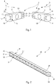
- the device 1, according to the invention and one embodiment of which is shown schematically in the figure 1 is a contactless power supply and data communication device.
- This device 1 is intended to be arranged in an aircraft in order to transmit data as well as electrical energy to equipment of said aircraft, in particular to equipment mounted on seats, in particular on passenger seats of a passenger plane. transportation.
- the device 1 can be adapted to any type of vehicle comprising equipment requiring electrical power and data transmission.
- data communication via “visible light” or via “light signals” refers to all wireless communication technologies based on the use of visible light, namely wavelength between 480nm and 650nm, also called “VLC” (for "Visible Light Communication” in English).
- VLC visible Light Communication
- the communication units 2 and 3 communicate data via the “Li-Fi” technology (for “Light Fidelity” in English) which uses the coding and the exchange of data by light amplitude modulation.
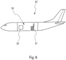
- the device 1 is configured to allow transmission of data and electrical power from a wall of the aircraft AC ( figure 6 ) to at least one seat of said aircraft AC.
- the communication unit 2 and the induction transmitter 4 are arranged in a wall 6 ( figure 4 ) of the aircraft and the communication unit 3 and the induction receiver 5 are arranged in a seat 7A ( figure 4 ) of said aircraft.
- the communication units 2 and 3 each comprise at least one transmission component and/or at least one reception component so as to be able to exchange data bidirectionally, that is to say in both directions, from communication unit 2 to communication unit 3 and from communication unit 3 to communication unit 2.
- the transmitting component corresponds to a micro light-emitting diode (often abbreviated as micro LED or in micro LED for "micro Light Emitting Diode” in English) which is able to be modulated at very high frequency
- the reception component corresponds to a photoreceptor able to pick up the modulated signals generated by the light-emitting microdiode.
- the term “microdiode” will be used alone to refer to such a light-emitting microdiode.
- the induction transmitter 4 and the induction receiver 5 each comprise a coil, preferably a flexible coil. These coils are capable of transmitting, in the usual way, electrical power by induction from the induction transmitter 4 to the induction receiver 5.
- the communication units 2 and 3 are arranged so as to be able to communicate, in the usual way, data via light signals. It is considered that said communication units 2 and 3 are able to communicate between them when they are arranged face to face and that at least one of the transmission components of one of the communication units is facing one of the reception components of the other communication unit. Preferably, the distance between the communication units 2 and 3 is of the order of a few centimeters.
- the induction transmitter 4 and the induction receiver 5 are arranged so that the induction transmitter 4 can transmit, in the usual way, electrical power by induction to the induction receiver 5.
- the induction transmitter 4 is arranged facing the induction receiver 5, at a distance of a few centimeters at most.
- the device 1 comprises a first transmission module 8 corresponding to a (single) structural block (that is to say to a single piece).
- This first transmission module 8 comprises the communication unit 2 and the induction transmitter 4.
- the device 1 comprises a second transmission module 9 also corresponding to a (single) structural block (i.e. say to one piece).
- This second transmission module 9 comprises the communication unit 3 and the induction receiver 5.
- the transmission modules 8 and 9 can, for example, correspond to boxes configured to receive at least one communication unit 2 or 3 (which can be identical), as well as either an induction transmitter 4 or an induction receiver 5.
- the transmission modules 8 and 9 have the shape of a rectangular parallelepiped.
- Each of said transmission modules 8 and 9 is provided with a so-called “front” face and a so-called “rear” face.
- the transmission module 8 is provided with a front face 10 and a rear face 11, and the transmission module 9 is provided with a front face 12 and a rear face 13.
- the front faces 10 and 12 are the faces intended to be arranged facing each other, while the rear faces 11 and 13 are the faces intended to be fixed, respectively, to the wall 6 and the seat 7.
- the rear faces 11 and 13 are , in particular, intended to make it possible to interface between the transmission modules 8 and 9 and the systems of the aircraft, as specified below.
- the wall 6 comprises an added element capable of receiving the transmission module 8.
- this added element corresponds to a chute as described below.
- the transmission module 8 is fixed directly to the wall 6 by means of fixing elements, for example by glue or screws.
- the transmission module 8 can be embedded in a housing provided for this purpose in the wall 6.
- the transmission module 9 is fixed to the seat 7A by means of a fixing element, for example by glue or screws.
- a fixing element for example by glue or screws.
- it can be integrated directly into the seat 7, for example thanks to a housing provided for this purpose in which it is mounted.
- the communication unit 2 comprises a microdiode 14 and a photoreceiver 15, and the communication unit 3 comprises a microdiode 16 and a photoreceiver 17. Furthermore, said communication units 2 and 3 are configured so that the microdiode 14 is capable of transmitting data in the form of light signals to the photoreceptor 17, which the latter is capable of detecting. Similarly, the microdiode 16 is capable of transmitting data in the form of light signals to the photoreceptor 15, which the latter is capable of detecting.
- the communication units 2 and 3 each comprise a plurality of microdiodes as well as a plurality of photoreceptors. Furthermore, each microdiode of a communication unit 2, 3 is capable of transmitting signals to at least one photoreceiver of the other communication unit. Conversely, each photoreceiver of a communication unit is capable of detecting signals emitted by at least one of the microdiodes of the other communication unit.
- the communication units 2 and 3 can each comprise a plurality of assemblies each comprising at least one microdiode and at least one photoreceptor.
- the communication unit 2 comprises a first assembly 18 comprising the microdiode 14 and the photoreceiver 15, and a second assembly 19 comprising a microdiode 20 and a photoreceiver 21.
- the communication unit 3 also comprises a first assembly 22 comprising the microdiode 16 and the photoreceptor 17, and a second assembly 23 comprising a microdiode 25 and a photoreceptor 24.
- sets 18 and 22 and sets 19 and 23 can be used differently.
- the sets 18 and 22 are intended for the operation of the communication units 2 and 3 in a usual context, while the sets 19 and 23 are intended for a redundancy function.
- the sets 18 and 22 operate, ie exchange data, while sets 19 and 23 are on standby, ie are powered but do not exchange data.
- the sets 19 and 23 are put into operation.
- Such an implementation makes it possible to avoid a cut in communications in the event of a failure of this type.
- sets 18 and 22 and sets 19 and 23 operate simultaneously.
- Such an implementation makes it possible to communicate a large quantity of data rapidly.
- this implementation is used occasionally to optimize the speed of data transmission. For example, in a normal regime, only sets 18 and 22 work and in a particular regime requiring the transfer of a large quantity of data, sets 19 and 23 are put into operation, in parallel with sets 18 and 22, in order to be able to communicate more data quickly.
- each module 8 and 9 may comprise a single connector grouping together the functions of data transmission and electrical energy or several separate connectors, in particular a connector for the transmission of data and a connector for the transmission of electrical energy.
- the device 1 comprises a chute 26 represented on the figure 2 , which is arranged on the wall 6 of the aircraft, as specified below.
- This chute 26 is configured to be able to receive a plurality of transmission modules 8.
- each of the transmission modules 8 has in particular a size and a shape such that it can be introduced (mounted) in the chute 26.
- the chute 26 can be an element attached and fixed to a surface of the wall 6 or an element arranged in a housing provided for this purpose, for example by being screwed or glued thereto.
- the trunking 26 is provided with holes 27, for example round, configured to leave access to the connectors of the wall 6 so that the connectors of the transmission modules 8 can be connected thereto.
- This chute 26 can be made of different materials, and preferably of plastic.
- the chute 26 corresponds to a rectilinear elongated element having a profile, namely a cross section, in the shape of a square "U" (that is to say whose bottom is not curved but straight), open at its longitudinal ends.
- the chute 26 has a bottom 28, lateral sides 29 and 30 and an open face 31.
- the open face 31 has two edges 32 and 33 corresponding to orthogonal extensions of the lateral sides 29 and 30, said edges 32 and 33 forming between them an opening 34.
- the opening 34 has a rectangular shape extending over the entire length of the chute 26 and it opens out at the longitudinal ends of said chute 26.
- the bottom 28 of the chute 26 has an outer face 35 (namely oriented towards the outside of the "U" shape) which may include fixing elements in order to fix said bottom 28 on the wall 6, for example by face or bonding.
- the bottom 28 also includes the holes 27 which are through holes allowing the transmission modules 8 to be connected to the connectors (not shown) of the wall 6.
- device 1 comprises at least one cover 36 ( picture 3 ) intended to be arranged on the chute 26 ( figure 2 ).
- the cover 36 is provided with at least one translucent zone able to let the light signals emitted by the communication units 2 and 3 pass so that said communication units 2 and 3 can exchange data via these light signals.
- cover 36 may also be transparent, at least in part.
- the cover 36 is intended to be arranged on the chute 26 by clips 40.
- the cover 36 corresponds to an elongated plate 37, preferably thin (of the order of a millimeter), of the same length as the chute 26 and provided, on one of its faces, with a flat surface 38, and on its opposite face, with a surface 39 provided with two clips 40.
- the surface 38 is intended to be oriented towards the outside of the chute 26 while surface 39 is intended to be oriented towards the inside of chute 26, cover 36 being fixed to chute 26 by means of clips 40.
- the clips 40 correspond to two shapes extruded over the entire length of the cover 36. These shapes are substantially orthogonal to the plate 37 of the cover 36.
- the clips 40 are provided, at their free ends, with hook shapes 41 capable of to cooperate elastically with the edges 32 and 33 of the open face 31 of the chute 26 so as to be able to easily mount and dismount the cover 36.
- the cover 36 can be fixed on the chute 26 in a different way, for example by being slid into a rail (not shown) arranged along said chute 26.
- the device 1 may comprise a plurality of covers 36.
- it may comprise shorter covers 36 and distributed over the entire length of the chute 26, each of these caches 36 being individually removable.
- the plate 37 of the cover 36 is made of a translucent material, for example a thermoplastic polymer, capable of allowing the transmission of light signals, in particular between the communication modules 8 and 9.
- the cover 36 can also comprise an opaque plate 37 provided with a plurality of translucent (or transparent) zones, which are provided at the level of the arrangement of the transmission modules 8 and 9.
- At least a part of the surface 38 of the cover 36 can comprise information, for example inscriptions or decorations in the form of messages glued, drawn or engraved.
- the device 1 may comprise another cover (not shown) intended to be arranged on the seat 7A at the level of the transmission module 9 and having for example characteristics similar to those of the cover 36.
- the device 1 comprises a protection element (not shown) intended to prevent access to the space situated between the transmission modules 8 and 9 and thus to avoid a disturbance or an impediment to the transmission of signals.
- the protection element is intended to be arranged between the wall 6 and the seat 7A and preferably has a narrow and elongated shape so as to be able to be inserted between the wall 6 and the seat 7A, and to cover all or part the length of the chute 26.
- the protection element is removably fixed by usual fixing means.
- the protection element can correspond to a rigid tablet, for example made of plastic, or to a flexible sheath, for example made of rubber.
- the protection element corresponds to an extension of at least one of the lateral sides 29 and 30 of the chute 26 ( picture 2 ). This extension extends from the chute 26 towards the seat 7A and therefore makes it possible to prevent access to the space situated between the transmission modules 8 and 9.
- the protection element can also be fixed to the seat 7A.
- the wall 6 of the aircraft is composed of a plurality of wall sections assembled together. Each of these wall sections corresponds to a panel 45 able to be juxtaposed and assembled with other similar panels in order to form the wall 6.
- the panel 45 comprises an upper part 46, provided with portholes 47, and a lower part 48.
- the chute 26 has the same length as the panel 45 and it is arranged at the level of the interface between the upper part 46 and the lower part 48 of said panel 45.
- chute 26 is configured so that when the panels are assembled to form wall 6, it is aligned with the chutes of adjacent panels.
- the device 1 as described above is part of a data communication and power supply system 50 intended to be integrated into an AC aircraft ( figure 6 ), and which comprises at least one such device 1.
- the system 50 comprises a plurality of devices 1, as well as a data management unit 51 and a power supply unit 52.
- the data management unit 51 is configured to manage the communication of data from the communication units 2 and 3 of devices 1
- the power supply unit 52 is configured to supply electric power to the inductive emitters 4 of devices 1.
- the system 50 comprises connections 53 arranged in the wall 6 and allowing the data management unit 51 to be connected to the communication units 2 via the connectors (not shown) of the wall 6.
- the links 53 correspond to usual cables for data communication, for example Ethernet or optical cables.
- the system 50 also includes connections 54 arranged in the wall 6 and allowing the electrical power management unit 52 to be connected to the induction transmitters 4 via connectors (not shown) of the wall 6.
- the links 54 correspond to usual electric cables for the electric power supply.
- the system 50 is intended to equip a cabin 55 of an aircraft, part of which has been shown on the figure 4 , in order to communicate data to the seats of said cabin 55 and supply them with electrical energy.
- the cabin 55 corresponds to at least a part of the cockpit of the aircraft, preferably a part intended to receive passengers, and it comprises in particular a floor 56, at least one wall 6 and at least one row of seats 57 comprising a seat 7A arranged along the wall 6 and at least one other said auxiliary seat 7B.
- the row of seats 57 comprises two auxiliary seats 7B and one seat 7A.
- These seats 7A and 7B are linked together in the usual way in order to form the row of seats 57 and more particularly, they have the usual connections and links between them making it possible to communicate data and a power supply between each of the seats 7A and 7B of the row of seats 57.
- This data communication and this power supply are carried out from the seat closest to the wall 6, namely the seat 7A which is the seat intended to include the transmission module 9, to the seats 7B.
- the seat 7A and 7B it is bidirectional.
- the system 50 offers great flexibility for its installation and that of the rows of seats.
- the system 50 is particularly suitable for a reconfiguration of the cabin 55 comprising a modification of the location of at least one row of seats 57.
- the devices 1 of the system 50 make it possible to communicate data and to transmit electrical energy between the walls 6 and the rows of seats 57 without contact, namely without physical connection between them.
- the transmission modules 8, arranged in the walls 6, can be moved in order to be positioned at desired positions along said walls 6. Consequently, it is possible to move rows of seats 57 along the longitudinal direction X-X of the cabin 55, in one direction or the other, and to easily adapt the position of the associated transmission modules 8, to the new positions of the rows of seats 57.
Landscapes
- Engineering & Computer Science (AREA)
- Computer Networks & Wireless Communication (AREA)
- Aviation & Aerospace Engineering (AREA)
- Physics & Mathematics (AREA)
- Electromagnetism (AREA)
- Signal Processing (AREA)
- Power Engineering (AREA)
- Computing Systems (AREA)
- Optical Communication System (AREA)
- Near-Field Transmission Systems (AREA)
Applications Claiming Priority (1)
| Application Number | Priority Date | Filing Date | Title |
|---|---|---|---|
| FR2110261 | 2021-09-29 |
Publications (1)
| Publication Number | Publication Date |
|---|---|
| EP4159623A1 true EP4159623A1 (de) | 2023-04-05 |
Family
ID=78332955
Family Applications (1)
| Application Number | Title | Priority Date | Filing Date |
|---|---|---|---|
| EP22196492.7A Pending EP4159623A1 (de) | 2021-09-29 | 2022-09-20 | Vorrichtung zur kontaktlosen datenkommunikation und stromversorgung, insbesondere für ein flugzeug |
Country Status (3)
| Country | Link |
|---|---|
| US (1) | US20230099152A1 (de) |
| EP (1) | EP4159623A1 (de) |
| CN (1) | CN115871932A (de) |
Citations (4)
| Publication number | Priority date | Publication date | Assignee | Title |
|---|---|---|---|---|
| EP0718945A2 (de) * | 1992-01-17 | 1996-06-26 | The Wiremold Company | Zusammenbau für Leitungskanal |
| US20190349082A1 (en) * | 2016-11-21 | 2019-11-14 | Lufthansa Technik Ag | Two-way data communication system for aircraft cabins |
| US10494098B2 (en) * | 2017-02-16 | 2019-12-03 | Inflight Investments Inc. | Sidewall seat track mounted USB power and communication hub for passenger aircraft |
| US20200322048A1 (en) * | 2019-04-05 | 2020-10-08 | Airbus Operations Gmbh | Optical Wireless Communication Network For Aircraft |
Family Cites Families (3)
| Publication number | Priority date | Publication date | Assignee | Title |
|---|---|---|---|---|
| US5336849A (en) * | 1992-01-17 | 1994-08-09 | The Wiremold Company | Raceway assembly for power and communications conductors |
| US20140226983A1 (en) * | 2013-02-13 | 2014-08-14 | Teac Aerospace Technologies, Inc. | In-flight li-fi media distribution system |
| US20160134127A1 (en) * | 2014-11-10 | 2016-05-12 | Eaton Corporation | Wireless power system |
-
2022
- 2022-09-20 EP EP22196492.7A patent/EP4159623A1/de active Pending
- 2022-09-23 US US17/951,171 patent/US20230099152A1/en not_active Abandoned
- 2022-09-29 CN CN202211197530.0A patent/CN115871932A/zh active Pending
Patent Citations (4)
| Publication number | Priority date | Publication date | Assignee | Title |
|---|---|---|---|---|
| EP0718945A2 (de) * | 1992-01-17 | 1996-06-26 | The Wiremold Company | Zusammenbau für Leitungskanal |
| US20190349082A1 (en) * | 2016-11-21 | 2019-11-14 | Lufthansa Technik Ag | Two-way data communication system for aircraft cabins |
| US10494098B2 (en) * | 2017-02-16 | 2019-12-03 | Inflight Investments Inc. | Sidewall seat track mounted USB power and communication hub for passenger aircraft |
| US20200322048A1 (en) * | 2019-04-05 | 2020-10-08 | Airbus Operations Gmbh | Optical Wireless Communication Network For Aircraft |
Also Published As
| Publication number | Publication date |
|---|---|
| CN115871932A (zh) | 2023-03-31 |
| US20230099152A1 (en) | 2023-03-30 |
Similar Documents
| Publication | Publication Date | Title |
|---|---|---|
| EP1479194B1 (de) | Lokales netzwerk zum austausch von daten zwischen mobilen personalcomputern für flugzeugpassagiere | |
| EP3983263B1 (de) | Träger um einen sitz zu einem kommunikationsnetzwerk zu verbinden | |
| EP3267232B1 (de) | Verbindungssystem einer vielzahl von steckerstiften an eine monoblockanordnung, bestehend aus einem gehäusepaneel eines elektronischen geräts und einer vielzahl von buchsen | |
| FR2804546A1 (fr) | Appareils electriques modulaires et enveloppe les comportant | |
| EP3520586B1 (de) | Flugzeug mit im rumpf verteilten computern | |
| FR2791185A1 (fr) | Connecteur basse tension pourvu d'un adaptateur et adaptateur pour un tel connecteur | |
| CA1233564A (fr) | Tete de lecture de marques portees par un document | |
| EP2355636B1 (de) | Anschlusseinheit mindestens einer elektronischen Ausrüstung in einem Luftfahrzeug | |
| FR3007239A1 (fr) | Procede d'integration de module d'interconnexion amovible dans un meuble, meuble ainsi equipe et aeronef comportant une baie constituee de tels meubles | |
| FR2859330A1 (fr) | Dispositif de communication mono-voie pour fibre optique | |
| EP3804280B1 (de) | System zur übertragung über signale vom typ li-fi | |
| EP2333912B1 (de) | Elektrische verbindungsvorrichtung | |
| EP1145045B9 (de) | Verbessertes system für geophysikalische datenerfassungs | |
| EP4159623A1 (de) | Vorrichtung zur kontaktlosen datenkommunikation und stromversorgung, insbesondere für ein flugzeug | |
| FR3032572A1 (fr) | Systeme de commande et dispositif abonne d'un reseau de communication d'un systeme de commande | |
| FR3038274A1 (fr) | Systeme de raccordement electrique d'un equipement de cabine d'un avion a un systeme de controle et a au moins une source d'alimentation electrique dudit avion | |
| FR2928507A1 (fr) | Reseau et rail de transport d'energie et de donnees multimedias | |
| EP2050213B1 (de) | Passives optisches fernnetz mit externer modulation eines optischen verstärkungssignals | |
| FR3057054B1 (fr) | Module de refroidissement et unite electronique comportant un tel module | |
| EP3513513B1 (de) | Leuchte, die mit einem telekommunikationsnetzwerk verbunden werden kann | |
| FR3078171A1 (fr) | Equipement electrique comportant une premiere partie et une deuxieme partie isolee electriquement de la premiere partie | |
| FR2589288A1 (fr) | Dispositif de connexion decentralisee d'un organe a une unite de commande programmable | |
| EP4494278B1 (de) | Sitz mit einem datenkommunikationsmodul nach li-fi-technologie | |
| EP3520587B1 (de) | Elektronische einheit mit reversiblen modulen | |
| BE1025517B1 (fr) | Poteau de lampadaire a modules fonctionnels |
Legal Events
| Date | Code | Title | Description |
|---|---|---|---|
| PUAI | Public reference made under article 153(3) epc to a published international application that has entered the european phase |
Free format text: ORIGINAL CODE: 0009012 |
|
| STAA | Information on the status of an ep patent application or granted ep patent |
Free format text: STATUS: THE APPLICATION HAS BEEN PUBLISHED |
|
| AK | Designated contracting states |
Kind code of ref document: A1 Designated state(s): AL AT BE BG CH CY CZ DE DK EE ES FI FR GB GR HR HU IE IS IT LI LT LU LV MC MK MT NL NO PL PT RO RS SE SI SK SM TR |
|
| STAA | Information on the status of an ep patent application or granted ep patent |
Free format text: STATUS: REQUEST FOR EXAMINATION WAS MADE |
|
| 17P | Request for examination filed |
Effective date: 20231002 |
|
| RBV | Designated contracting states (corrected) |
Designated state(s): AL AT BE BG CH CY CZ DE DK EE ES FI FR GB GR HR HU IE IS IT LI LT LU LV MC MK MT NL NO PL PT RO RS SE SI SK SM TR |
|
| STAA | Information on the status of an ep patent application or granted ep patent |
Free format text: STATUS: EXAMINATION IS IN PROGRESS |
|
| 17Q | First examination report despatched |
Effective date: 20250520 |