EP4160865A1 - Dispositif d'alimentation électrique de secours - Google Patents
Dispositif d'alimentation électrique de secours Download PDFInfo
- Publication number
- EP4160865A1 EP4160865A1 EP21811989.9A EP21811989A EP4160865A1 EP 4160865 A1 EP4160865 A1 EP 4160865A1 EP 21811989 A EP21811989 A EP 21811989A EP 4160865 A1 EP4160865 A1 EP 4160865A1
- Authority
- EP
- European Patent Office
- Prior art keywords
- battery
- voltage
- power supply
- charging
- battery pack
- Prior art date
- Legal status (The legal status is an assumption and is not a legal conclusion. Google has not performed a legal analysis and makes no representation as to the accuracy of the status listed.)
- Pending
Links
Images

Classifications
-
- H—ELECTRICITY
- H02—GENERATION; CONVERSION OR DISTRIBUTION OF ELECTRIC POWER
- H02J—ELECTRIC POWER NETWORKS; CIRCUIT ARRANGEMENTS OR SYSTEMS FOR SUPPLYING OR DISTRIBUTING ELECTRIC POWER; SYSTEMS FOR STORING ELECTRIC ENERGY
- H02J9/00—Circuit arrangements for emergency or stand-by power supply, e.g. for emergency lighting
- H02J9/04—Circuit arrangements for emergency or stand-by power supply, e.g. for emergency lighting in which the distribution system is disconnected from the normal source and connected to a standby source
- H02J9/06—Circuit arrangements for emergency or stand-by power supply, e.g. for emergency lighting in which the distribution system is disconnected from the normal source and connected to a standby source with automatic change-over, e.g. UPS systems
- H02J9/061—Circuit arrangements for emergency or stand-by power supply, e.g. for emergency lighting in which the distribution system is disconnected from the normal source and connected to a standby source with automatic change-over, e.g. UPS systems for DC powered loads
-
- H—ELECTRICITY
- H01—ELECTRIC ELEMENTS
- H01M—PROCESSES OR MEANS, e.g. BATTERIES, FOR THE DIRECT CONVERSION OF CHEMICAL ENERGY INTO ELECTRICAL ENERGY
- H01M10/00—Secondary cells; Manufacture thereof
- H01M10/24—Alkaline accumulators
- H01M10/30—Nickel accumulators
-
- H—ELECTRICITY
- H01—ELECTRIC ELEMENTS
- H01M—PROCESSES OR MEANS, e.g. BATTERIES, FOR THE DIRECT CONVERSION OF CHEMICAL ENERGY INTO ELECTRICAL ENERGY
- H01M10/00—Secondary cells; Manufacture thereof
- H01M10/42—Methods or arrangements for servicing or maintenance of secondary cells or secondary half-cells
- H01M10/46—Accumulators structurally combined with charging apparatus
-
- H—ELECTRICITY
- H02—GENERATION; CONVERSION OR DISTRIBUTION OF ELECTRIC POWER
- H02J—ELECTRIC POWER NETWORKS; CIRCUIT ARRANGEMENTS OR SYSTEMS FOR SUPPLYING OR DISTRIBUTING ELECTRIC POWER; SYSTEMS FOR STORING ELECTRIC ENERGY
- H02J7/00—Circuit arrangements for charging or discharging batteries or for supplying loads from batteries
- H02J7/50—Circuit arrangements for charging or discharging batteries or for supplying loads from batteries acting upon multiple batteries simultaneously or sequentially
-
- H—ELECTRICITY
- H02—GENERATION; CONVERSION OR DISTRIBUTION OF ELECTRIC POWER
- H02J—ELECTRIC POWER NETWORKS; CIRCUIT ARRANGEMENTS OR SYSTEMS FOR SUPPLYING OR DISTRIBUTING ELECTRIC POWER; SYSTEMS FOR STORING ELECTRIC ENERGY
- H02J7/00—Circuit arrangements for charging or discharging batteries or for supplying loads from batteries
- H02J7/90—Regulation of charging or discharging current or voltage
- H02J7/96—Regulation of charging or discharging current or voltage in response to battery voltage
-
- H—ELECTRICITY
- H02—GENERATION; CONVERSION OR DISTRIBUTION OF ELECTRIC POWER
- H02J—ELECTRIC POWER NETWORKS; CIRCUIT ARRANGEMENTS OR SYSTEMS FOR SUPPLYING OR DISTRIBUTING ELECTRIC POWER; SYSTEMS FOR STORING ELECTRIC ENERGY
- H02J7/00—Circuit arrangements for charging or discharging batteries or for supplying loads from batteries
- H02J7/50—Circuit arrangements for charging or discharging batteries or for supplying loads from batteries acting upon multiple batteries simultaneously or sequentially
- H02J7/585—Sequential battery discharge in systems with a plurality of batteries
-
- H—ELECTRICITY
- H02—GENERATION; CONVERSION OR DISTRIBUTION OF ELECTRIC POWER
- H02J—ELECTRIC POWER NETWORKS; CIRCUIT ARRANGEMENTS OR SYSTEMS FOR SUPPLYING OR DISTRIBUTING ELECTRIC POWER; SYSTEMS FOR STORING ELECTRIC ENERGY
- H02J7/00—Circuit arrangements for charging or discharging batteries or for supplying loads from batteries
- H02J7/855—Circuit arrangements for charging or discharging batteries or for supplying loads from batteries with circuits adapted for supplying loads from the battery
-
- H—ELECTRICITY
- H02—GENERATION; CONVERSION OR DISTRIBUTION OF ELECTRIC POWER
- H02J—ELECTRIC POWER NETWORKS; CIRCUIT ARRANGEMENTS OR SYSTEMS FOR SUPPLYING OR DISTRIBUTING ELECTRIC POWER; SYSTEMS FOR STORING ELECTRIC ENERGY
- H02J9/00—Circuit arrangements for emergency or stand-by power supply, e.g. for emergency lighting
- H02J9/04—Circuit arrangements for emergency or stand-by power supply, e.g. for emergency lighting in which the distribution system is disconnected from the normal source and connected to a standby source
- H02J9/06—Circuit arrangements for emergency or stand-by power supply, e.g. for emergency lighting in which the distribution system is disconnected from the normal source and connected to a standby source with automatic change-over, e.g. UPS systems
- H02J9/068—Electronic means for switching from one power supply to another power supply, e.g. to avoid parallel connection
-
- Y—GENERAL TAGGING OF NEW TECHNOLOGICAL DEVELOPMENTS; GENERAL TAGGING OF CROSS-SECTIONAL TECHNOLOGIES SPANNING OVER SEVERAL SECTIONS OF THE IPC; TECHNICAL SUBJECTS COVERED BY FORMER USPC CROSS-REFERENCE ART COLLECTIONS [XRACs] AND DIGESTS
- Y02—TECHNOLOGIES OR APPLICATIONS FOR MITIGATION OR ADAPTATION AGAINST CLIMATE CHANGE
- Y02E—REDUCTION OF GREENHOUSE GAS [GHG] EMISSIONS, RELATED TO ENERGY GENERATION, TRANSMISSION OR DISTRIBUTION
- Y02E60/00—Enabling technologies; Technologies with a potential or indirect contribution to GHG emissions mitigation
- Y02E60/10—Energy storage using batteries
Definitions
- the present invention relates to a backup power supply device.
- a backup power supply device for supplying power to a load device, which is being powered from a commercial power source, in place of the commercial power source in the event of a power failure.
- a boosting DC/DC converter may in some cases be provided in the backup power supply device to boost an input voltage and apply the boosted input voltage to the battery unit.
- the battery voltage of the battery unit may increase to be higher than the voltage of an input line to the load device, and thus the battery voltage of the battery unit may directly be applied to the load device.
- a backup power supply device includes a plurality of battery units
- a method is adopted in which the battery units is divided into two groups, one group is kept at a voltage which can be output to the load device without being charged while the other group is being charged, and then the output switch is turned on. This method makes it possible to ensure that the power supply to the load device is not interrupted even for a moment under a power failure.
- An object of the present invention which has been made in view of such a problem, is to provide a backup power supply device in which charging time is shortened.
- a backup power supply device for supplying power to a load device when power supply from a main power supply to the load device stops, comprising: first and second battery packs each including a secondary battery cell and connected in parallel to each other; a charging circuit for charging the first and second battery packs with power from the main power supply; a first discharging switch that connects and discharges the first battery pack to the load device; a second discharging switch that connects and discharges the second battery pack to the load device; and a control unit for controlling the charging circuit and the first and second discharging switches, wherein the control unit includes comparison means for comparing a first battery voltage of the first battery pack, a second battery voltage of the second battery pack, and an output voltage from the main power supply.
- the control unit sets the first discharging switch and the second discharging switch to an ON-state.
- the control unit sets the first discharging switch and the second discharging switch to an OFF-state to continue charging of the first battery pack.
- the control unit continues the charging of the first battery pack without charging the second battery pack, and stops the charging of the first battery pack when the first battery voltage reaches a full charge voltage higher than the upper limit voltage.
- control unit starts charging of the second battery pack after the first battery voltage has fallen below the upper limit voltage, and stops the charging of the second battery pack when the second battery voltage reaches the full charge voltage. And the control unit switches the first and second discharging switches to ON after the second battery voltage has fallen below the output voltage.
- both the first and second discharging switches are set to ON. Therefore, if the power supply from the main power supply stops, it is possible to supply power to the load device without interruption.
- both the discharging switches are set to OFF.
- the battery voltage of the first battery pack exceeds the dischargeable upper limit voltage
- the charging of the first battery pack is continued.
- the battery voltage of the second battery pack is maintained to be equal to or less than the upper limit voltage without charging the second charging pack in preparation for a power failure of the main power supply.
- both the first and second discharging switches are switched to an ON-state. In this way, while the battery voltage of the battery pack is higher than the output voltage of the main power supply, the discharging switch is kept off. Therefore, if power supply from the main power supply is not interrupted, discharging from the battery pack to the load device is not conducted, so that the charging time of the overall backup power supply device is shortened.
- charging time is a time from the time when the backup power supply device is connected to the main power supply to start charging of the battery unit to the time when each battery pack constituting the battery unit is fully charged to set all the battery packs to be in a standby state in which they can discharge to the load device.
- a second aspect of the present invention further comprises a discharging resistor for forcibly dropping the battery voltage of the fully-charged first battery pack or second battery pack from the full charge voltage to the upper limit voltage in the first aspect.
- the secondary battery cell is a nickel-hydrogen battery in the first or second aspect.
- the secondary battery cell is a nickel-hydrogen battery
- the time required to fully charge the backup power supply device can be shortened.
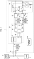
- the backup power supply device 1 is a device which is connected in parallel to a power supply 2 as a main power supply and supplies power to a load device 3 in order to continue the operation of the load device 3 when power supply from the power supply 2 to the load device 3 is interrupted due to a power failure or the like.
- the power supply 2 is, for example, a power supply device that outputs DC power of an output voltage V0 by power feeding from a commercial power source.
- the load device 3 is an electric device that operates with DC power of the voltage V0.
- the voltage V0 is, for example, 26.2 to 28.8V.
- the backup power supply device 1 includes input/output terminals 10, a battery unit 20, a charging circuit 30, a discharging circuit 40, and a control device 50.
- the input/output terminals 10 are connected to a power supply line L for supplying power from the power supply 2 to the load device 3. DC power of the voltage V0 is supplied to the input/output terminals 10.
- the input voltage V0 at the input/output terminals 10 of the backup power supply device 1 is equal to the output voltage V0 of the power supply 2.
- the battery unit 20 includes a first battery pack 21 and a second battery pack 22.
- the first and second battery packs 21, 22 are connected in parallel to each other.
- Each of the battery packs 21 and 22 is formed by connecting a plurality of alkaline secondary battery cells such as nickel-hydrogen secondary batteries in series or in parallel.
- the rated voltage of each of the battery pack 21 and 22 is equal to the voltage V0 of the power supply. Further, each of the battery packs 21 and 22 has a full charge voltage higher than the rated voltage.
- the battery unit 20 includes a first voltage detection unit 23 for detecting a first battery voltage across the first battery pack 21, a second voltage detection unit 24 for detecting a second battery voltage across the second battery pack 22, an ammeter (not shown) for detecting the charging current to each of the battery packs 21 and 22, and a thermometer (not shown) for detecting the temperature of the battery unit 20.
- the charging circuit 30 is a circuit for charging the first and second battery packs 21 and 22, and includes a DC/DC converter 31, a selector switch S0, first and second constant current control circuits 32 and 33, and first and second charging switches S1, S2.
- the DC/DC converter 31 is a voltage converter for boosting the output voltage V0 from the power supply 2 to the full charge voltages of the battery packs 21 and 22.
- the DC/DC converter 31 is connected to the input/output terminals 10 on the input side thereof, and is connected to the battery unit 20 via the selector switch S0 on the output side thereof.
- the DC/DC converter 31 is selectively and electrically connected to the battery unit 20 by switching the selector switch S0.
- the DC/DC converter 31 is an input/output isolated type DC/DC converter.
- the selector switch S0 is set at a contact "a"
- the DC/DC converter 31 is not connected to the battery unit 20, and the input/output terminals 10 are directly connected to the battery unit 20.
- the selector switch S0 is set at a contact "b”
- the DC/DC converter 31 is connected to the battery unit 20, and a voltage suitable for full charge is applied to the battery unit 20.
- the first charging switch S1 is a switch for switching on/off charging of the first battery pack 21.
- the first charging switch S1 has one end which is connected to the selector switch S0 via the first constant current control circuit 32, and the other end which is connected to the first battery pack 21. When the first charging switch S1 is turned ON, the first battery pack 21 is charged with constant current from the first constant current control circuit 32.
- the second charging switch S2 is a switch for switching on/off charging of the second battery pack 22.
- the second charging switch S2 has one end which is connected to the selector switch S0 via the second constant current control circuit 33, and the other end which is connected to the second battery pack 22. When the second charging switch S2 is turned ON, the second battery pack 22 is charged with constant current from the second constant current control circuit 33.
- the first and second constant current control circuits 32 and 33 are control circuits for supplying constant current to the battery packs 21 and 22 to which the first and second constant current control circuits 32 and 33 are respectively connected.
- the first and second charging switches S1 and S2 are set to ON/OFF with control signals from the control device 50 described later.
- the discharging circuit 40 includes a first discharging switch S3, a second discharging switch S4, and a discharging resistor R.
- the first discharging switch S3 is a switch for switching on/off discharging from the first battery pack 21 to the load device 3.
- the first discharging switch S3 has one end which is connected to the first battery pack 21, and the other end which is connected to the input/output terminals 10. When the first discharging switch S3 is set to ON, the first battery pack 21 is set to be capable of discharging to the load device 3.
- the second discharging switch S4 is a switch for switching on/off discharging of the second battery pack 22.
- the second discharging switch S4 has one end which is connected to the second battery pack 22, and the other end which is connected to the input/output terminals 10. When the second discharging switch S4 is set to ON, the second battery pack 22 is set to be capable of discharging to the load device 3.
- the discharging resistor R has one end which is connected to the first battery pack 21 via a first auxiliary switch S5 and also connected to the second battery pack 22 via a second auxiliary switch S6.
- the discharging resistor R has the other end which is connected to a reference potential. Therefore, when the first auxiliary switch S5 is set to ON, the first battery pack 21 discharges to the discharging resistor R. On the other hand, when the second auxiliary switch S6 is set to ON, the second battery pack 22 discharges to the discharging resistor R. Further, a diode D1 is inserted between the first auxiliary switch S5 and the first battery pack 21.
- the diode D1 has an anode connected to the first battery pack 21, and a cathode connected to the first auxiliary switch S5. Furthermore, a diode D2 is inserted between the second auxiliary switch S6 and the second battery pack 22. The diode D2 has an anode connected to the second battery pack 22, and a cathode connected to the second auxiliary switch S6.
- the control device 50 includes a microcomputer as a control unit, and controls the charging circuit 30 and the discharging circuit 40 based on the input voltage V0 at the input/output terminals 10, the first battery voltage V1 of the first battery pack 21, and the second battery voltage V2 of the second battery pack 22.
- the control device 50 has a voltage detection unit 51 for detecting the input voltage V0, and compares the input voltage V0, the first battery voltage V1 of the first battery pack 21, and the second battery voltage V2 of the second battery pack 22 as comparison means.
- control device 50 outputs control signals for controlling ON/OFF of the selector switch S0, the first charging switch S1, the second charging switch S2, the first discharging switch S3, the second discharging switch S4, the first auxiliary switch S5, and the second auxiliary switch S6.
- FIG. 2 is a time chart showing the charging/discharging control of the backup power supply device 1.
- charging of the first and second battery packs 21 and 22 is started.
- the control device 50 switches the selector switch S0 to the contact "a" and turns the first and second charging switches S1 and S2 to ON to charge the first battery pack 21 and the second battery pack 22 under the constant current control based on the output voltage V0 from the power supply 2.
- the first and second discharge switches S3 and S4 are set to ON so that discharging from the first battery pack 21 and the second battery pack 22 to the load device 3 is allowable in preparation for a power failure.
- Both the first and second auxiliary switches S5 and S6 are set to OFF-state. Therefore, if the power supply from the power supply 2 stops, power supply from the backup power supply device 1 to the load device 3 is started without causing any instantaneous power failure, and the power supply to the load device 3 is continued.
- both the first and second discharging switches S3 and S4 are switched to OFF. Therefore, as the discharge from the battery unit 20 to the load device 3 is stopped, the electric charges charged in the battery packs 21 and 22 do not flow into the load device 3. On the other hand, charging of the first and second battery packs 21 and 22 is continued. Therefore, when the power supply from the power supply 2 stops after time t3, the control device 50 detects this power failure and switches the first and second discharging switches S3 and S4 to ON, thereby causing the battery packs 21 and 22 to discharge to the load device 3. Therefore, a slight instantaneous power failure occurs.
- the control device 50 switches the second discharging switch S4 to ON, which makes it possible to supply power from the second battery pack 22 to the load device 3.
- the dischargeable upper limit voltage is a voltage that can be applied across the load device 3, and the dischargeable upper limit voltage is set depending on the specification of the load device 3.
- the first battery voltage V1 of the first battery pack 21 reaches a full charge voltage higher than the dischargeable upper limit voltage. Therefore, the first charging switch S1 is switched to OFF to stop charging of the first battery pack 21. Then, the first auxiliary switch S5 is set to ON to cause forced discharging from the first battery pack 21 to the discharging resistor R, thereby dropping the first battery voltage V1 to the upper limit voltage. At this time, if the power supply from the power supply 2 to the load device 3 stops, the battery voltage V2 of the second battery pack 22 is equal to or less than the upper limit voltage, so that it is possible to supply power from the second battery pack 22 to the load device 3 by switching the second discharging switch S4 to ON.
- the first auxiliary switch S5 is switched to OFF to stop forced discharging.
- the second charging switch S2 is set to ON to start charging of the second battery pack 22.
- the control device 50 that has detected the power failure of the power supply 2 switches only the first discharging switch S3 to ON, whereby it is possible to supply power to the load device 3 from the first battery pack 21 whose battery voltage is equal to or less than the upper limit voltage.
- the second auxiliary switch S6 is set to ON to cause forced discharging from the second battery pack 22 to the discharging resistor R.
- the control device 50 detects stoppage of the power supply from the power supply 2 and then switches only the first discharging switch S3 to ON, whereby it is possible to supply power to the load device 3 from the first battery pack 21 whose battery voltage is equal to or less than the upper limit voltage.
- both the first and second battery packs 21 and 22 are fully charged, and enter a standby state in preparation for stoppage of power supply from the power supply 2. Since both the battery voltages V1 and V2 are higher than the output voltage V0 of the power supply 2, both the first and second discharging switches S3 and S4 are kept in an OFF-state.
- the control device 50 detects stoppage of the power supply from the power supply 2 and then switches one or both of the first discharging switch S3 and the second discharging switch S4 to ON, whereby it is possible to supply power from the battery unit 20 to the load device 3.
- the first and second discharging switches S3 and S4 are switched to ON-state, which allows discharging from the backup power supply device 1 to the load device 3 to be performed. In this case, power can be supplied from the backup power supply device 1 to the load device 3 without causing any instantaneous power failure.
- the selector switch is switched from the contact "b" to the contact "a” to disconnect the DC/DC converter 31 from the charging circuit 30.
- This switching timing is not limited to the time t8, but the above may be performed at any appropriate timing insofar as the switching timing is after the time t7.
- both the first and second discharging switches S3 and S4 are set to OFF to stop the discharging from the battery unit 20 to the load device 3. Therefore, if no power failure of the power supply 2 occurs, the battery packs 21 and 22 constituting the battery unit 20 can be fully charged in a short time. Therefore, the discharging switch OFF period from the time t3 to the time t9 can be shortened.
- all of the battery voltages V1 and V2 of the first and second battery packs 21 and 22 are equal to or less than the upper limit voltage. Therefore, for example, if the power supply from the power supply 2 stops due to a power failure, both the first and second discharging switches S3 and S4 are switched to ON by the control signals from the control device 50, which makes it possible to discharge to the load device 3 from any of the first and second battery packs 21 and 22, so that a large amount of electric power that can be supplied to the load device 3 can be ensured.
- the battery packs 21 and 22 are alternately charged, and the battery voltage of any one of the battery packs exceeds the upper limit voltage due to charging, so that it is impossible to cause the any one of the battery pack to discharge to the load device 3.
- the battery voltage of the other battery pack is maintained to be equal to or less than the upper limit voltage without charging the other battery pack. Therefore, if the power supply from the power supply 2 stops due to a power failure, the discharging switch corresponding to the battery pack whose battery voltage is equal to or less than the upper limit voltage is switched to ON with the control signal from the control device 50. Therefore, it is possible to cause this battery pack to discharge to the load device 3.
- preparations are made for power failures by securing a dischargeable battery pack.
- the number of battery packs to be connected in parallel is not limited to two, and it may be an appropriate plural number.
- a plurality of battery packs are divided into at least two groups, and the battery voltages of the battery packs of one of the group are kept to be equal to or less than the upper limit voltage while the battery packs of the other group are being charged with the battery voltages thereof exceeding the upper limit voltage.
- both the first and second discharging switches are switched OFF to stop discharging from the battery unit to the load device. Therefore, if a power failure does not occur in the power supply 2 during charging of the battery packs 21 and 22, it is possible to shorten the charging time required until the backup power supply device 1 is ready for being in the discharging standby state by fully charging each battery unit, as compared with a case where the first and second discharge switches S3 and S4 are kept to ON at all times.
- the battery voltage of one battery pack is maintained to be equal to or less than the upper limit voltage while the other battery pack is being charged so as to reach the full charge voltage with the battery voltage thereof exceeding the upper limit voltage. Accordingly, if a power failure occurs in the power supply 2, power supply to the load device 3 is enabled. Therefore, the time for which an instantaneous power failure occurs can be shortened.
Landscapes
- Engineering & Computer Science (AREA)
- Power Engineering (AREA)
- Manufacturing & Machinery (AREA)
- Chemical & Material Sciences (AREA)
- Chemical Kinetics & Catalysis (AREA)
- Electrochemistry (AREA)
- General Chemical & Material Sciences (AREA)
- Business, Economics & Management (AREA)
- Emergency Management (AREA)
- Charge And Discharge Circuits For Batteries Or The Like (AREA)
- Stand-By Power Supply Arrangements (AREA)
Applications Claiming Priority (2)
| Application Number | Priority Date | Filing Date | Title |
|---|---|---|---|
| JP2020091527A JP7534058B2 (ja) | 2020-05-26 | 2020-05-26 | バックアップ電源装置 |
| PCT/JP2021/017150 WO2021241136A1 (fr) | 2020-05-26 | 2021-04-30 | Dispositif d'alimentation électrique de secours |
Publications (2)
| Publication Number | Publication Date |
|---|---|
| EP4160865A1 true EP4160865A1 (fr) | 2023-04-05 |
| EP4160865A4 EP4160865A4 (fr) | 2023-11-29 |
Family
ID=78744453
Family Applications (1)
| Application Number | Title | Priority Date | Filing Date |
|---|---|---|---|
| EP21811989.9A Pending EP4160865A4 (fr) | 2020-05-26 | 2021-04-30 | Dispositif d'alimentation électrique de secours |
Country Status (4)
| Country | Link |
|---|---|
| US (1) | US11996730B2 (fr) |
| EP (1) | EP4160865A4 (fr) |
| JP (1) | JP7534058B2 (fr) |
| WO (1) | WO2021241136A1 (fr) |
Families Citing this family (4)
| Publication number | Priority date | Publication date | Assignee | Title |
|---|---|---|---|---|
| CN115768651A (zh) * | 2020-07-31 | 2023-03-07 | 松下知识产权经营株式会社 | 备用电源系统和移动体 |
| EP4178068B1 (fr) * | 2021-10-29 | 2024-04-17 | Nanjing Chervon Industry Co., Ltd. | Dispositif de charge |
| JP7731303B2 (ja) * | 2022-02-04 | 2025-08-29 | Fdk株式会社 | 蓄電デバイス |
| JP2023177920A (ja) * | 2022-06-03 | 2023-12-14 | Fdk株式会社 | 蓄電制御装置、蓄電装置、充電残時間算出方法、及び充電残時間算出プログラム |
Family Cites Families (8)
| Publication number | Priority date | Publication date | Assignee | Title |
|---|---|---|---|---|
| US6476583B2 (en) | 2000-07-21 | 2002-11-05 | Jomahip, Llc | Automatic battery charging system for a battery back-up DC power supply |
| JP2012130158A (ja) | 2010-12-15 | 2012-07-05 | Nippon Telegr & Teleph Corp <Ntt> | 電源装置 |
| JP5786330B2 (ja) | 2010-12-24 | 2015-09-30 | ソニー株式会社 | 放電制御装置及び放電制御方法 |
| JP2013126331A (ja) | 2011-12-15 | 2013-06-24 | Fdk Twicell Co Ltd | 電子機器、電池ユニット |
| JP6242008B2 (ja) | 2014-06-25 | 2017-12-06 | Fdk株式会社 | 無停電電源装置 |
| JP6410299B2 (ja) * | 2014-07-07 | 2018-10-24 | Fdk株式会社 | 無停電電源装置 |
| US10923944B2 (en) * | 2018-03-05 | 2021-02-16 | Eaton Intelligent Power Limited | Methods, systems and devices for managing batteries of uninterruptible power supplies (UPSs) and related external battery modules (EBMs) |
| US11183854B1 (en) * | 2019-05-20 | 2021-11-23 | Amazon Technologies, Inc. | Recharging of backup battery units using intermittent charging cycles |
-
2020
- 2020-05-26 JP JP2020091527A patent/JP7534058B2/ja active Active
-
2021
- 2021-04-30 WO PCT/JP2021/017150 patent/WO2021241136A1/fr not_active Ceased
- 2021-04-30 US US17/999,636 patent/US11996730B2/en active Active
- 2021-04-30 EP EP21811989.9A patent/EP4160865A4/fr active Pending
Also Published As
| Publication number | Publication date |
|---|---|
| US20230238824A1 (en) | 2023-07-27 |
| JP2021191041A (ja) | 2021-12-13 |
| WO2021241136A1 (fr) | 2021-12-02 |
| JP7534058B2 (ja) | 2024-08-14 |
| EP4160865A4 (fr) | 2023-11-29 |
| CA3178960A1 (fr) | 2021-12-02 |
| US11996730B2 (en) | 2024-05-28 |
Similar Documents
| Publication | Publication Date | Title |
|---|---|---|
| US11996730B2 (en) | Backup power supply device | |
| US10404095B2 (en) | Uninterruptible power supply unit | |
| US11081899B2 (en) | Battery system | |
| US7928691B2 (en) | Method and system for cell equalization with isolated charging sources | |
| CN112655131B (zh) | 蓄电装置和充电方法 | |
| EP4142097A1 (fr) | Dispositif d'alimentation électrique sans interruption | |
| EP4266539A1 (fr) | Dispositif d'alimentation électrique | |
| EP3163712A1 (fr) | Système d'alimentation électrique sans coupure | |
| JPH07231584A (ja) | 装置に電力を供給するシステムならびに電力貯蔵装置の寿命および容量を評価する方法 | |
| US20120032513A1 (en) | Battery management circuit, battery module and battery management method | |
| US20100231177A1 (en) | Battery pack and charger system | |
| JP2012182857A (ja) | 直流電源装置 | |
| JP2002058170A (ja) | 無停電電源装置 | |
| JP3249261B2 (ja) | パック電池 | |
| JP2009148110A (ja) | 充放電器とこれを用いた電源装置 | |
| US12374884B2 (en) | Backup power supply device | |
| JP4724726B2 (ja) | 直流電源システムおよびその充電方法 | |
| JP6644443B2 (ja) | 切換装置、それを備える電力ユニットおよびそれを備える電力システム | |
| CA3178960C (fr) | Dispositif d'alimentation electrique de secours | |
| US20240088691A1 (en) | Battery life extension method | |
| JPH1146450A (ja) | 太陽電池式電源装置 | |
| KR101401805B1 (ko) | 휴대용 기기의 전원관리 제어장치 및 그 제어방법 | |
| EP4340161A1 (fr) | Procédé d'extension de durée de vie de batterie | |
| EP4601147A1 (fr) | Procédé de prévention de décharge excessive de batterie et système de batterie fournissant celui-ci | |
| JPH06197464A (ja) | 充放電装置 |
Legal Events
| Date | Code | Title | Description |
|---|---|---|---|
| STAA | Information on the status of an ep patent application or granted ep patent |
Free format text: STATUS: THE INTERNATIONAL PUBLICATION HAS BEEN MADE |
|
| PUAI | Public reference made under article 153(3) epc to a published international application that has entered the european phase |
Free format text: ORIGINAL CODE: 0009012 |
|
| STAA | Information on the status of an ep patent application or granted ep patent |
Free format text: STATUS: REQUEST FOR EXAMINATION WAS MADE |
|
| 17P | Request for examination filed |
Effective date: 20221123 |
|
| AK | Designated contracting states |
Kind code of ref document: A1 Designated state(s): AL AT BE BG CH CY CZ DE DK EE ES FI FR GB GR HR HU IE IS IT LI LT LU LV MC MK MT NL NO PL PT RO RS SE SI SK SM TR |
|
| DAV | Request for validation of the european patent (deleted) | ||
| DAX | Request for extension of the european patent (deleted) | ||
| REG | Reference to a national code |
Ref country code: DE Ref legal event code: R079 Free format text: PREVIOUS MAIN CLASS: H02J0007020000 Ipc: H02J0009060000 |
|
| A4 | Supplementary search report drawn up and despatched |
Effective date: 20231102 |
|
| RIC1 | Information provided on ipc code assigned before grant |
Ipc: H02J 7/00 20060101ALI20231026BHEP Ipc: H02J 9/06 20060101AFI20231026BHEP |