EP4161008A1 - Dispositif, système et procédé de traitement d'informations - Google Patents
Dispositif, système et procédé de traitement d'informations Download PDFInfo
- Publication number
- EP4161008A1 EP4161008A1 EP21812076.4A EP21812076A EP4161008A1 EP 4161008 A1 EP4161008 A1 EP 4161008A1 EP 21812076 A EP21812076 A EP 21812076A EP 4161008 A1 EP4161008 A1 EP 4161008A1
- Authority
- EP
- European Patent Office
- Prior art keywords
- data
- group
- transmission rate
- pieces
- information processing
- Prior art date
- Legal status (The legal status is an assumption and is not a legal conclusion. Google has not performed a legal analysis and makes no representation as to the accuracy of the status listed.)
- Pending
Links
Images





Classifications
-
- H—ELECTRICITY
- H04—ELECTRIC COMMUNICATION TECHNIQUE
- H04L—TRANSMISSION OF DIGITAL INFORMATION, e.g. TELEGRAPHIC COMMUNICATION
- H04L47/00—Traffic control in data switching networks
- H04L47/70—Admission control; Resource allocation
- H04L47/76—Admission control; Resource allocation using dynamic resource allocation, e.g. in-call renegotiation requested by the user or requested by the network in response to changing network conditions
- H04L47/762—Admission control; Resource allocation using dynamic resource allocation, e.g. in-call renegotiation requested by the user or requested by the network in response to changing network conditions triggered by the network
-
- H—ELECTRICITY
- H04—ELECTRIC COMMUNICATION TECHNIQUE
- H04L—TRANSMISSION OF DIGITAL INFORMATION, e.g. TELEGRAPHIC COMMUNICATION
- H04L47/00—Traffic control in data switching networks
- H04L47/10—Flow control; Congestion control
- H04L47/25—Flow control; Congestion control with rate being modified by the source upon detecting a change of network conditions
-
- H—ELECTRICITY
- H04—ELECTRIC COMMUNICATION TECHNIQUE
- H04L—TRANSMISSION OF DIGITAL INFORMATION, e.g. TELEGRAPHIC COMMUNICATION
- H04L47/00—Traffic control in data switching networks
- H04L47/10—Flow control; Congestion control
- H04L47/26—Flow control; Congestion control using explicit feedback to the source, e.g. choke packets
- H04L47/263—Rate modification at the source after receiving feedback
Definitions
- the present invention relates to an information processing device, an information processing system, and an information processing method.
- Patent Literature 1 JP 2002-026986 A
- the present disclosure proposes an information processing device, an information processing system, and an information processing method capable of efficiently dividing the communication resource to transmit data.
- an information processing device comprises: a data classification unit that classifies a plurality of pieces of data transmitted via a network into one or more groups based on a sharing state of a communication resource between the data; and a target transmission rate setting unit that sets, for each group, a target transmission rate of each data belonging to the group based on a setting reference of the target transmission rate defined for each group.
- an information processing system comprises: a plurality of transmission devices; and the information processing device that sets each of target transmission rates of a plurality of pieces of data transmitted from the plurality of transmission devices.
- an information processing method in which an information process of the information processing device is executed by a computer is provided.
- FIG. 1 is a schematic diagram of an information processing system 1.
- the information processing system 1 includes a plurality of devices. When there are a plurality of devices of the same type, these devices are denoted by the same reference numerals. To distinguish the devices from each other, a number is added after the reference numeral indicating the device.
- band means the amount of data that can be transmitted per unit time.
- “Sharing a band” means that a communication resource having a defined total band is shared by a plurality of pieces of data. That is, “sharing a band” means that the communication resource is divided and allocated to a plurality of pieces of data for transmission.
- the “band” in this case has the same meaning as the communication resource.
- the information processing system 1 includes, for example, a plurality of cameras 100, a plurality of transmission devices 200, a plurality of reception devices 400, a controller 500, and a switcher 600.
- N is an integer of 2 or more pieces of cameras 100, N pieces of transmission devices 200, and N pieces of reception devices 400 are provided.
- the transmission device 200 includes a video encoder 201 and a transmission module 202.
- the video encoder 201 encodes and compresses a video signal output from the camera 100.
- the transmission module 202 transmits video data (video packet) obtained from the compression to a network 300.
- the transmission module 202 monitors a state of the network 300 and determines a current transmission rate.
- the transmission module 202 instructs the video encoder 201 on encoding and the transmission rate, so that the data can be transmitted within a constant delay range.
- the reception device 400 includes a reception module 401 and a video decoder 402.
- the reception module 401 receives data (video packet) transmitted from the transmission device 200 via the network 300.
- the video decoder 402 extracts and decodes the video encoded data from the video packet, and restores the video signal.
- the video decoder 402 outputs the restored video signal to the switcher 600.
- the reception module 401 performs error correction and retransmission instruction, and corrects an error within a possible range.
- the switcher 600 acquires a plurality of video signals output from the plurality of reception devices 400.
- a video signal output from another equipment (not illustrated) can be input to the switcher 600.
- the switcher 600 switches between the plurality of input video signals for broadcasting or distribution.
- the switcher 600 can also mix two or more video signals for broadcasting or distribution.
- the switcher 600 can also perform processing such as effect adding and caption multiplexing on an output video.
- a video captured by the camera 100 is transmitted to a broadcast video production device such as the switcher 600 using a dedicated cable to switch between videos to be transmitted and add a caption.
- a broadcast video production device such as the switcher 600
- 5G next-generation communication standard
- large-capacity and low-latency communication is being realized.
- the large-capacity and low-latency wireless communication enables video transmission by wireless low-latency streaming, which replaces conventional video transmission using a dedicated cable. This enables production with high mobility and low cost.
- a plurality of cameras 100 are generally used to capture videos from various angles so that the videos are broadcast or distributed by appropriately switching between them.
- a larger band is necessary as the number of videos to be transmitted increases.
- the available band is often limited. Therefore, it is necessary to increase the compression rate in order to transmit more videos in the limited band. Nevertheless, increasing the compression ratio may deteriorate the image quality.
- the information processing system 1 detects a group of data transmitted along the same transmission path and sharing a band.
- the information processing system 1 groups the group of data sharing the band and allocates a bandwidth according to a role of each data in the same group. Then, the data is encoded and transmitted at a transmission rate corresponding to the allocated band. This reduces a deterioration in image quality of a video to be broadcast or distributed, leading to the production of a live video having high image quality.
- the information processing system 1 sets the transmission rate of the important video currently broadcast or distributed to be higher than that of the other videos by controlling the multiplexing rate of the plurality of videos. This reduces the deterioration in image quality of the video to be broadcast or distributed. What is important at this time is to grasp the connection state of the network 300 and to switch control according to whether to perform the multiplexing rate control, and this function is undertaken by the controller 500.
- FIG. 2 is a schematic diagram of the controller 500.
- the controller 500 is an information processing device that processes information acquired from the transmission device 200 and the switcher 600 and controls various devices constituting the information processing system 1.
- the controller 500 sets the target transmission rate of each of the plurality of pieces of data transmitted from the plurality of transmission devices 200, based on the acquired information.
- the controller 500 includes, for example, an information acquisition unit 501, a sharing state determination unit 502, a data classification unit 503, and a target transmission rate setting unit 504.
- the information acquisition unit 501 acquires information necessary for band sharing estimation from the transmission device 200.
- the sharing state determination unit 502 determines a sharing state of a band between data in the network 300 (sharing state of the communication resource) based on the acquired information.
- the data classification unit 503 classifies the plurality of pieces of data transmitted via the network 300 into one or more groups based on the sharing state of the band between the data.
- the target transmission rate setting unit 504 sets, for each group, the target transmission rate of each data belonging to the group based on a setting reference of the target transmission rate defined for each group. For example, the target transmission rate setting unit 504 determines the role assigned to each of the plurality of pieces of data belonging to the same group based on the On-Air information from the switcher 600. The target transmission rate setting unit 504 determines the size of the band to be allocated to each data according to the role of each data. The target transmission rate setting unit 504 sets the target transmission rate of each transmission device 200 based on the size of the band determined for each data. Each transmission device 200 transmits data in accordance with the state of the network 300, using the instructed target transmission rate as a target value.
- the N pieces of data transmitted from the N pieces of transmission devices 200 are classified into a plurality of groups by the data classification unit 503.
- the plurality of pieces of data are classified into a band sharing group and a band non-sharing group according to the sharing state of the band.
- the band sharing group is a group in which the band is shared between the data.
- the band non-sharing group is a group in which the band is not shared between the data.
- the band sharing group is classified into two types according to whether or not a band allocation ratio can be controlled between the data (whether or not the band can be lent and borrowed).
- the plurality of pieces of data are classified into three groups (a first group, second group, and third group).
- the first group is a group in which the band is shared between the data and the band allocation ratio can be controlled between the data (band sharing, controllable).
- the second group is a group in which the band is shared between the data but the band allocation ratio cannot be controlled between the data (band sharing and uncontrollable).
- the third group is a group in which the band is not shared with any other data (no band sharing).
- the target transmission rate setting unit 504 changes a method of setting the transmission rate according to the type of the band sharing group. For example, for the first group, the target transmission rate setting unit 504 determines the band to be allocated to each data according to the role of each data. The target transmission rate setting unit 504 dynamically changes the size of the band to be allocated to each data according to the change in the role of each data (first band control). For the second group, the target transmission rate setting unit 504 allocates a fixed band to each data according to a video profile (second band control). For the third group, the target transmission rate setting unit 504 individually sets the transmission rate of the data (third band control).
- Which group the data belongs to is determined by, for example, two types of classification processing.
- the band sharing group is identified based on the network management information.
- the network management information includes, for example, information on a transmission path of data in the network 300.
- the network management information includes a type of the network 300, a parameter of the network 300, and the like.
- the sharing state determination unit 502 determines the sharing state of the band between the data in the network 300 based on the transmission path of each data in the network 300.
- the sharing state determination unit 502 determines that a plurality of pieces of data whose type of the network 300 and parameter of the network 300 coincide with each other share the band.
- the data classification unit 503 classifies the plurality of pieces of data determined by the sharing state determination unit 502 to share the band into the same group.
- the band sharing estimation processing is processing of observing an influence of data transmission of a certain transmission device 200 on data transmission of another transmission device 200 and estimating the sharing state of the band between the data based on an observation result.
- An object of the band sharing estimation processing is to detect information about the sharing state of the band that cannot be found only from the network management information.
- the sharing state determination unit 502 determines that the plurality of pieces of data share the band.
- the data classification unit 503 classifies a plurality of pieces of data belonging to the same group and having a correlation in the change in the band used into the first group.
- the data classification unit 503 classifies a plurality of pieces of data belonging to the same group and having no correlation in the change in the band used into the second group.
- FIG. 3 is a flowchart of first classification processing.
- Step S1 the information acquisition unit 501 acquires network management information of the network 300 used for transmission from a certain transmission device 200.
- Step S2 the sharing state determination unit 502 compares the network management information acquired from the certain transmission device 200 with network management information acquired from another transmission device 200.
- the other transmission device 200 used for the comparison is a transmission device 200 for which the group the transmitted data belongs to, that is, the band sharing group or the band non-sharing group, is known.
- FIG. 4 is a flowchart illustrating an example of the comparison processing of network management information as described in Step S2.
- the sharing state determination unit 502 selects one transmission device 200 from among the N pieces of transmission devices 200.
- the sharing state determination unit 502 determines whether or not the type of the network 300 to which the selected transmission device 200 is connected is the same as the type of the network 300 to which the other transmission device 200 is connected.
- Examples of the type of the network 300 include a mobile network (LTE/5G), WiFi, an Internet access line, a dedicated line, a closed network, and the like.
- Step S11 When it is not determined in Step S11 that the type of the network 300 is the same (Step S11: No), the processing proceeds to Step S12. In Step S12, the sharing state determination unit 502 determines that band sharing has not been found, and ends the processing.
- Step S11 When it is determined in Step S11 that the type of the network 300 is the same (Step S11: Yes), the processing proceeds to Step S13.
- Step S13 the sharing state determination unit 502 determines whether or not the parameter of the network 300 to which the selected transmission device 200 is connected is the same as the parameter of the network 300 to which the other transmission device 200 is connected.
- Examples of the parameter of the network 300 include those described in FIG. 5 .
- Examples of the parameter of the mobile network include cell ID and channel ID of the mobile network, Internet connection point information from the mobile core network, and network slicing information (in the case of 5G).
- An example of the parameter of Wifi is the SSID of the access point.
- An example of the parameter of the Internet access line is use line information.
- An example of the parameter of the dedicated line is use line information.
- An example of the closed network parameter is network information (such as data path information).
- Step S13 when it is not determined in Step S13 that the parameters are the same (Step S13: No), the processing proceeds to Step S14.
- Step S14 the sharing state determination unit 502 determines that band sharing has not been found, and ends the processing.
- Step S13 When it is determined in Step S13 that the parameters are the same (Step S13: Yes), the processing proceeds to Step S15.
- Step S15 the sharing state determination unit 502 determines that band sharing has been found, and ends the processing.
- Step S3 the sharing state determination unit 502 determines whether or not band sharing has been found between the data transmitted from the selected transmission device 200 and the data transmitted from the other transmission device 200.
- Step S3 When it is determined in Step S3 that band sharing has been found (Step S3: Yes), the processing proceeds to Step S4.
- Step S4 the data classification unit 503 classifies the data transmitted from the selected transmission device 200 into the same group as the group to which the data transmitted from the other transmission device 200 belongs.
- Step S3 When it is not determined in Step S3 that band sharing has been found (Step S3: No), the processing proceeds to Step S5.
- Step S5 the data classification unit 503 registers the data transmitted from the selected transmission device 200 to a new group. When there is no classified data in Step S2, the determination result of Step S3 is No.
- Step S6 the data classification unit 503 determines whether or not the above-described evaluation has been performed for all the transmission devices 200.
- Step S6 When it is determined in Step S6 that the above-described evaluation has been performed for all the transmission devices 200 (Step S6: Yes), the processing ends. When it is not determined in Step S4 that the above-described evaluation has been performed for all the transmission devices 200 (Step S6: No), the processing returns to Step S1. Then, the processing is repeated until the above-described evaluation is performed for all the transmission devices 200.
- FIG. 6 is a flowchart of second classification processing.
- Step S21 the controller 500 performs the band sharing estimation processing.
- An object of the band sharing estimation processing is to detect information about the sharing state of the band that cannot be detected by the first classification processing (identification of the band sharing group based on the network management information).
- FIG. 7 is a flowchart illustrating an example of the band sharing estimation processing.
- Step S31 the sharing state determination unit 502 selects one transmission device 200 from among the N pieces of transmission devices 200.
- the sharing state determination unit 502 increases the transmission rate of the selected transmission device 200.
- Step S32 the sharing state determination unit 502 checks whether the transmission bands of (N-1) pieces of the other transmission devices 200 have decreased.
- the decrease in the transmission band is detected based on an increase in a packet loss rate, a decrease in a receiving side throughput, an increase in a delay, and the like.
- Step S33 the sharing state determination unit 502 determines whether or not the band decrease has been found in one or more transmission devices 200 having a different group to which the data belongs from that of the selected transmission device 200, among (N-1) pieces of the other transmission devices 200.
- Step S33 When it is determined in Step S33 that band decrease has been found (Step S33: Yes), the processing proceeds to Step S34.
- Step S34 the data classification unit 503 determines that band sharing has been found between the data of the selected transmission device 200 and the data of the group in which band decrease has occurred in conjunction with the increase in the transmission rate of the selected transmission device 200. Then, the data classification unit 503 registers the groups in which band sharing has been found as the same group, and ends the processing.
- Step S33 When it is not determined in Step S33 that band decrease has been found (Step S33: No), the data classification unit 503 maintains the classification results of the data.
- Step S21 when the band sharing estimation processing of Step S21 ends, the processing proceeds to Step S22.
- the controller 500 performs band allocation ratio controllability estimation processing.
- the band allocation ratio controllability estimation processing is performed for the purpose of checking whether the band allocation ratio can be controlled between a plurality of pieces of data sharing the band in the same group.
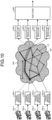
- FIGS. 9 and 10 are diagrams illustrating a state in which a band is shared by a plurality of pieces of data.
- data transmitted from the transmission device 200-1, data transmitted from the transmission device 200-2, and data transmitted from the transmission device 200-3 are transmitted along the same transmission path R.
- the transmission path R includes nodes ND and links LK of the network 300.
- a plurality of pieces of data whose transmission paths R are partially or entirely equal share a band. Therefore, in FIG. 9 , the data transmitted from the transmission device 200-1, the data transmitted from the transmission device 200-2, and the data transmitted from the transmission device 200-3 share a band.
- the data transmitted from the transmission device 200-1, the data transmitted from the transmission device 200-2, and the data transmitted from the transmission device 200-3 do not share the band with data from another equipment. Therefore, the band allocation ratio can be controlled among the data transmitted from the transmission device 200-1, the data transmitted from the transmission device 200-2, and the data transmitted from the transmission device 200-3.
- the transmission path R of the data transmitted from the transmission device 200-1, the data transmitted from the transmission device 200-2, and the data transmitted from the transmission device 200-3 overlaps with that of the data transmitted from another equipment in a section R0.
- the band of another transmission device 200 may not be increased because the band that becomes available after the reduction is used by the other equipment. Therefore, the band allocation ratio cannot be controlled between the data of the selected transmission device 200 and the data of the other transmission device 200.
- the controller 500 estimates whether the band allocation ratio can be controlled between a plurality of pieces of data sharing a band in the same group according to the band allocation ratio controllability estimation processing.
- FIG. 8 is a flowchart illustrating an example of the band allocation ratio controllability estimation processing.
- Step S41 the sharing state determination unit 502 selects one transmission device 200 from among the N pieces of transmission devices 200 and reduces the transmission rate of the selected transmission device 200.
- Step S42 the sharing state determination unit 502 checks whether or not the bands of data of (N-1) pieces of the other transmission devices 200 whose transmission rate have not been reduced have increased.
- the increase in the band is detected based on a decrease in the packet loss rate, an increase in the receiving side throughput, a decrease in the delay, and the like.
- Step S43 the sharing state determination unit 502 determines whether or not the bands of all the data belonging to the same group as that of the data of the selected transmission device 200 have increased.
- Step S43 When it is determined in Step S43 that the bands of all the other data of the same group have increased (Step S43: Yes), the processing proceeds to Step S44.
- Step S44 the data classification unit 503 estimates the group to which the data of the selected transmission device 200 belongs as the first group in which the band allocation ratio is controllable, and ends the processing.
- Step S43 When it is not determined in Step S43 that the bands of all the other data of the same group have increased (Step S43: No), the processing proceeds to Step S45.
- Step S45 the data classification unit 503 estimates the group to which the data of the selected transmission device 200 belongs as the second group in which the band allocation ratio is uncontrollable, and ends the processing.
- FIG. 11 is a diagram illustrating a specific example of the data classification processing.
- the above-described classification processing is applied to a system including eight transmission devices.
- Data transmitted from the eight transmission devices is classified into two band sharing groups (Group #1 and Group #3) and one band non-sharing group (Group #2) based on the network management information.
- the band sharing estimation processing is performed on the two band sharing groups (Group #1 and Group #3). As a result of the band sharing estimation processing, it is estimated that two band sharing groups (Group #1 and Group #3) share a band. Therefore, Group #3 is re-registered as Group #1.
- the band allocation ratio controllability estimation processing is performed on Group #1 to determine the type of the band sharing group.
- Group #1 is a group in which the band allocation ratio is controllable.
- the data transmitted from the eight transmission devices is classified into Group #1 (a group in which the pieces of data share the band and the band allocation ratio can be controlled between the data) and Group #2 (a group that does not share a band with any other data).
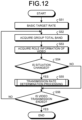
- FIG. 12 is a flowchart illustrating a method of controlling the transmission rate.
- processing of allocating more bandwidth of the total band of a group to data of an "On-Air video" and data of a "Next video" scheduled to be on the air next is performed for the group in which the band allocation ratio is controllable. This processing improves the image quality of the video to be broadcast or distributed.
- the target transmission rate setting unit 504 sets, for each data (video), a transmission rate at which the expected image quality is obtained as a basic target transmission rate.
- the basic target transmission rate of each data may be set to the same value.
- the basic target transmission rate may be different depending on each data.
- the sharing state determination unit 502 calculates, for each group, the total band of the network shared by the plurality of pieces of data in the group (group total band). For example, the sharing state determination unit 502 can identify the transmission path of each data from the network management information and calculate the group total band from the specification of the transmission path of each data. Alternatively, the sharing state determination unit 502 may acquire the transmittable rate detected from each transmission device 200 and calculate the group total band based on each of the acquired transmittable rates. The target transmission rate setting unit 504 acquires the group total band of each group from the sharing state determination unit 502.
- Step S53 the target transmission rate setting unit 504 acquires information on which video data is selected as the "On-Air video” or the “Next video” from the switcher 600.
- the "On-Air video” is a video that is currently being broadcast or distributed, output from the switcher 600.
- the “Next video” is a video that is scheduled to be broadcast or distributed next, output from the switcher 600.
- Step S54 the target transmission rate setting unit 504 determines whether or not the situation has changed. Examples of the change in the situation detected by the target transmission rate setting unit 504 include a change in the role information of the video and a change in the group total band. The target transmission rate setting unit 504 checks the situation at constant time intervals.
- Step S54 When it is determined in Step S54 that the situation has changed (Step S54: Yes), the processing proceeds to Step S55.
- the target transmission rate setting unit 504 determines the target transmission rate of each video.
- the target transmission rate setting unit 504 sets the transmission rate of each transmission device 200 using the determined target transmission rate.
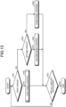
- FIG. 13 is a flowchart illustrating a method of determining the target transmission rate.
- Step S61 the target transmission rate setting unit 504 acquires data classification information (information indicating which group each data belongs to) from the data classification unit 503.
- the target transmission rate setting unit 504 selects one group from the plurality of groups classified by the data classification unit 503, and determines whether or not the selected group corresponds to the first group in which the band allocation ratio is controllable.
- Step S61 When it is determined in Step S61 that the selected group corresponds to the first group (Step S61: Yes), the processing proceeds to Step S62.
- Step S62 the target transmission rate setting unit 504 sets the target transmission rate of each data based on the first band control. Each transmission device 200 performs transmission using the target transmission rate set based on the first band control as a target value. Each transmission device 200 monitors the state of the network 300, and if the transmission band cannot be secured, performs transmission by reducing the transmission rate to an appropriate rate as necessary.
- FIG. 14 is a flowchart of the first band control.
- Step S71 the target transmission rate setting unit 504 determines whether or not the "On-Air video" exists in the group.
- Step S71 When it is determined in Step S71 that the "On-Air video" exists in the group (Step S71: Yes), the processing proceeds to Step S72.
- Step S72 the target transmission rate setting unit 504 sets the target transmission rate of the "On-Air video".
- the target transmission rate setting unit 504 calculates the maximum transmission rate that can be allocated to the "On-Air video" (an allocatable rate).
- the lowest rate is preset by the user as a minimum band for preventing the band of the remaining data from becoming zero.
- the target transmission rate setting unit 504 sets a smaller one of the basic target transmission rate and the allocatable rate of the "On-Air video" as the target transmission rate of the "On-Air video".
- Step S72 After the target transmission rate of the "On-Air video" is set in Step S72, or when it is not determined in Step S71 that the "On-Air video” exists in the group (Step S71: No), the processing proceeds to Step S73.
- Step S73 the target transmission rate setting unit 504 determines whether or not the "Next video" exists in the group.
- Step S73 When it is determined in Step S73 that the "Next video" exists in the group (Step S73: Yes), the processing proceeds to Step S74.
- Step S74 the target transmission rate setting unit 504 sets the target transmission rate of the "Next video".
- the target transmission rate setting unit 504 calculates an allocatable rate of the "Next video".
- the target transmission rate setting unit 504 sets a smaller one of the basic target transmission rate and the allocatable rate of the "Next video" as the target transmission rate of the "Next video".
- Step S74 After the target transmission rate of the "Next video" is set in Step S74, or when it is not determined in Step S73 that the "Next video" exists in the group (Step S73: No), the processing proceeds to Step S75.
- Step S75 the target transmission rate setting unit 504 sets the target transmission rates of the remaining data in the group.
- the target transmission rate setting unit 504 calculates an allocatable rate of the remaining data other than the "On-Air video" and the "Next video".
- the target transmission rate setting unit 504 divides the allocatable rate of the remaining data by the number of pieces of remaining data.
- the target transmission rate setting unit 504 dynamically changes the target transmission rate of each data belonging to the first group according to the role of each data.
- Step S61 when it is not determined in Step S61 that the selected group corresponds to the first group (Step S61: No), the processing proceeds to Step S64.
- the target transmission rate setting unit 504 determines whether or not the selected group corresponds to the second group in which the band allocation ratio is uncontrollable.
- Step S64 When it is determined in Step S64 that the selected group corresponds to the second group (Step S64: Yes), the processing proceeds to Step S65.
- the target transmission rate setting unit 504 sets the target transmission rate of each data based on the second band control.
- Each transmission device 200 performs transmission using the target transmission rate set based on the second band control as a target value.
- Each transmission device 200 monitors the state of the network 300, and if the transmission band cannot be secured, performs transmission by reducing the transmission rate to an appropriate rate as necessary.
- the target transmission rate setting unit 504 allocates a fixed band to each data based on the basic target transmission rate set in advance.
- the target transmission rate setting unit 504 sets the target transmission rate of all the data belonging to the second group based on a fixed ratio regardless of the role of each data.
- the target transmission rate setting unit 504 proportionally divides the group total band based on the basic target transmission rate of each data.
- Step S66 the target transmission rate setting unit 504 sets the target transmission rate of each data based on the third band control.
- the target transmission rate setting unit 504 sets the basic target transmission rate set in advance as the target transmission rate.
- Each transmission device 200 performs transmission using the target transmission rate set based on the third band control as a target value.
- Each transmission device 200 monitors the state of the network 300, and if the transmission band cannot be secured, performs transmission by reducing the transmission rate to an appropriate rate as necessary.
- Step S63 the target transmission rate setting unit 504 determines whether or not the target transmission rate has been set for all the groups classified by the data classification unit 503.
- Step S63 When it is determined in Step S63 that the target transmission rate has been set for all the groups (Step S63: Yes), the processing ends. When it is not determined in Step S63 that the target transmission rate has been set for all the groups (Step S63: No), the processing returns to Step S61, and the processing of Step S61 and the subsequent steps is repeated until the target transmission rate is set for all the groups.
- Step S56 the target transmission rate setting unit 504 determines whether or not the transmission of the video has ended based on the data acquired from each transmission device 200.
- Step S56: Yes the target transmission rate setting unit 504 ends the processing.
- Step S56: No the processing returns to Step S52, and the processing of Step S52 and the subsequent steps is repeated.
- the target transmission rates of the plurality of pieces of data transmitted from the plurality of transmission devices 200 are set.
- FIG. 15 is a diagram illustrating a state in which the bandwidth of data is switched according to a change in the role of the data.
- the number of cameras is four.
- Video data output from the four cameras (Cam #0, Cam #1, Cam #2, and Cam #3) are transmitted through the same transmission path.
- the allocation ratio of the band of each data is dynamically adjusted based on the first band control.
- the data of Cam #0 is an "On-Air video", and the data of Cam #1 is a "Next video”. More bandwidth is allocated to the data of Cam #0 and the data of Cam #1 than to the other data.
- the controller 500 includes the data classification unit 503 and the target transmission rate setting unit 504.
- the data classification unit 503 classifies the plurality of pieces of data transmitted via the network 300 into one or more groups, based on the sharing state of the communication resource between the data.
- the target transmission rate setting unit 504 sets, for each group, the target transmission rate of each data belonging to the group based on a setting reference of the target transmission rate defined for each group.
- the above-described information processing of the controller 500 is executed by a computer.
- the communication resource is efficiently allocated to the plurality of pieces of data based on the sharing state of the communication resource. As a result, the communication resource is effectively utilized.
- the controller 500 includes the sharing state determination unit 502.
- the sharing state determination unit 502 determines the sharing state of the communication resource between the data in the network 300 based on the transmission path of each data in the network 300.
- the data classification unit 503 classifies the plurality of pieces of data determined by the sharing state determination unit 502 to share the communication resource into the same group.
- the sharing state determination unit 502 determines that a plurality of pieces of data whose type of the network 300 and parameter of the network 300 coincide with each other share the communication resource.
- the sharing state determination unit 502 determines that the plurality of pieces of data share the communication resource.
- the data classification unit 503 classifies a plurality of pieces of data belonging to the same group and having a correlation in the change in the communication resource used into the first group in which the allocation ratio of the communication resource can be controlled between the data.
- the target transmission rate setting unit dynamically changes the target transmission rate of each data belonging to the first group according to the role of each data.
- the communication resource is efficiently allocated according to the role of the data.
- the data classification unit classifies a plurality of pieces of data belonging to the same group and having no correlation in the change in the communication resource used into the second group in which the allocation ratio of the communication resource cannot be controlled between the data.
- the target transmission rate setting unit sets the target transmission rate of all the data belonging to the second group based on a fixed ratio regardless of the role of each data.
- the information processing system 1 includes the plurality of transmission devices 200 and the controller 500.
- the controller 500 sets the target transmission rate of each of the plurality of pieces of data transmitted from the plurality of transmission devices 200.
- the present technique may also have the following configurations:
Landscapes
- Engineering & Computer Science (AREA)
- Computer Networks & Wireless Communication (AREA)
- Signal Processing (AREA)
- Data Exchanges In Wide-Area Networks (AREA)
Applications Claiming Priority (2)
| Application Number | Priority Date | Filing Date | Title |
|---|---|---|---|
| JP2020090962 | 2020-05-25 | ||
| PCT/JP2021/018564 WO2021241299A1 (fr) | 2020-05-25 | 2021-05-17 | Dispositif, système et procédé de traitement d'informations |
Publications (2)
| Publication Number | Publication Date |
|---|---|
| EP4161008A1 true EP4161008A1 (fr) | 2023-04-05 |
| EP4161008A4 EP4161008A4 (fr) | 2023-11-08 |
Family
ID=78744619
Family Applications (1)
| Application Number | Title | Priority Date | Filing Date |
|---|---|---|---|
| EP21812076.4A Pending EP4161008A4 (fr) | 2020-05-25 | 2021-05-17 | Dispositif, système et procédé de traitement d'informations |
Country Status (4)
| Country | Link |
|---|---|
| US (1) | US12355674B2 (fr) |
| EP (1) | EP4161008A4 (fr) |
| JP (1) | JP7673747B2 (fr) |
| WO (1) | WO2021241299A1 (fr) |
Families Citing this family (1)
| Publication number | Priority date | Publication date | Assignee | Title |
|---|---|---|---|---|
| CN116709210B (zh) * | 2023-06-16 | 2026-03-20 | 武汉迈威通信股份有限公司 | 一种无线广播业务报文增强传输方法 |
Family Cites Families (16)
| Publication number | Priority date | Publication date | Assignee | Title |
|---|---|---|---|---|
| JP2002026986A (ja) * | 2000-07-10 | 2002-01-25 | Matsushita Electric Ind Co Ltd | データ伝送装置、データ伝送方法および記録媒体 |
| WO2008137432A2 (fr) * | 2007-05-01 | 2008-11-13 | Dyyno | Partage d'informations et informations de mise en forme pour la transmission sur un réseau de communication |
| KR101518507B1 (ko) * | 2007-07-19 | 2015-05-11 | 한국전자통신연구원 | 영상신호 송수신 장치 및 방법 |
| WO2010047019A1 (fr) * | 2008-10-21 | 2010-04-29 | 日本電気株式会社 | Dispositif d'apprentissage de modèle statistique, procédé d'apprentissage de modèle statistique et programme |
| JP5454318B2 (ja) * | 2010-04-07 | 2014-03-26 | 富士通株式会社 | 帯域測定装置、帯域測定システム、帯域測定プログラム及び通信装置 |
| WO2012114728A1 (fr) * | 2011-02-25 | 2012-08-30 | パナソニック株式会社 | Procédé de traitement de données d'émission, procédé de traitement d'informations, dispositif d'émission et dispositif de réception |
| CN103733554A (zh) * | 2011-08-15 | 2014-04-16 | 夏普株式会社 | 无线发送装置、无线接收装置、程序、集成电路以及无线通信系统 |
| CN102761480B (zh) * | 2012-06-28 | 2017-11-28 | 中兴通讯股份有限公司 | 一种资源分配方法及装置 |
| JP6575091B2 (ja) * | 2015-03-20 | 2019-09-18 | 富士ゼロックス株式会社 | 旅程推定装置及びプログラム |
| US10772120B2 (en) * | 2015-04-17 | 2020-09-08 | Telefonaktiebolaget Lm Ericsson (Publ) | Method and access node for signaling scheduling information to terminal device and method and terminal device for performing scheduled communications |
| JP6401666B2 (ja) * | 2015-06-24 | 2018-10-10 | 日本電信電話株式会社 | 通信システム |
| KR20170017573A (ko) * | 2015-08-07 | 2017-02-15 | 삼성전자주식회사 | 영상 데이터 처리 방법 및 이를 지원하는 전자 장치 |
| JP6719492B2 (ja) * | 2018-02-26 | 2020-07-08 | 三菱電機株式会社 | ルール生成装置およびルール生成プログラム |
| WO2019215778A1 (fr) * | 2018-05-07 | 2019-11-14 | 日本電気株式会社 | Système de fourniture de données et système de collecte de données |
| WO2020008800A1 (fr) | 2018-07-06 | 2020-01-09 | ソニー株式会社 | Dispositif de commande de communication et procédé de commande de communication |
| CN112640515B (zh) | 2018-09-05 | 2024-04-09 | 索尼公司 | 通信控制设备、控制通信的方法及通信系统 |
-
2021
- 2021-05-17 WO PCT/JP2021/018564 patent/WO2021241299A1/fr not_active Ceased
- 2021-05-17 EP EP21812076.4A patent/EP4161008A4/fr active Pending
- 2021-05-17 JP JP2022526903A patent/JP7673747B2/ja active Active
- 2021-05-17 US US17/920,299 patent/US12355674B2/en active Active
Also Published As
| Publication number | Publication date |
|---|---|
| US12355674B2 (en) | 2025-07-08 |
| JP7673747B2 (ja) | 2025-05-09 |
| WO2021241299A1 (fr) | 2021-12-02 |
| US20230132800A1 (en) | 2023-05-04 |
| JPWO2021241299A1 (fr) | 2021-12-02 |
| EP4161008A4 (fr) | 2023-11-08 |
Similar Documents
| Publication | Publication Date | Title |
|---|---|---|
| US11503307B2 (en) | System and method for automatic encoder adjustment based on transport data | |
| US9516210B2 (en) | Method and apparatus for prioritizing data transmission in a wireless broadcasting system | |
| EP3225040B1 (fr) | Liaisons redondantes permettant une communication fiable | |
| US20200007823A1 (en) | Predictive network management for real-time video with varying video and network conditions | |
| US8873414B2 (en) | Communication apparatus, communication method, and communication system | |
| EP1911305A1 (fr) | Transmission de paquets ethernet au moyen d'une interface cpri | |
| US11722913B2 (en) | Multichannel communication systems | |
| US20140253741A1 (en) | Camera system and switching device | |
| AU2021200428B2 (en) | System and method for automatic encoder adjustment based on transport data | |
| EP4161008A1 (fr) | Dispositif, système et procédé de traitement d'informations | |
| CN117858203B (zh) | 一种无线视频监控自动选网方法和系统 | |
| US12185224B2 (en) | Wireless communication apparatus and wireless communication method | |
| US9490994B2 (en) | Reception device, transmission/reception system, reception method, and program | |
| US20190090307A1 (en) | Information processing device, information processing system, and information processing method | |
| EP4322495A1 (fr) | Procédé et système de transmission de données au moyen de signaux radio et d'adaptation de débit de transmission d'une ou de plusieurs entités au moyen d'un codage de données | |
| KR101095352B1 (ko) | 단일선로 전송방식 고화질 디지털 폐쇄회로텔레비젼 시스템 | |
| JP2024136814A (ja) | 映像監視システム | |
| US20220338103A1 (en) | Wireless terminal station device, management station device, wireless communication system and wireless communication method |
Legal Events
| Date | Code | Title | Description |
|---|---|---|---|
| STAA | Information on the status of an ep patent application or granted ep patent |
Free format text: STATUS: THE INTERNATIONAL PUBLICATION HAS BEEN MADE |
|
| PUAI | Public reference made under article 153(3) epc to a published international application that has entered the european phase |
Free format text: ORIGINAL CODE: 0009012 |
|
| STAA | Information on the status of an ep patent application or granted ep patent |
Free format text: STATUS: REQUEST FOR EXAMINATION WAS MADE |
|
| 17P | Request for examination filed |
Effective date: 20221212 |
|
| AK | Designated contracting states |
Kind code of ref document: A1 Designated state(s): AL AT BE BG CH CY CZ DE DK EE ES FI FR GB GR HR HU IE IS IT LI LT LU LV MC MK MT NL NO PL PT RO RS SE SI SK SM TR |
|
| DAV | Request for validation of the european patent (deleted) | ||
| DAX | Request for extension of the european patent (deleted) | ||
| REG | Reference to a national code |
Ref country code: DE Ref legal event code: R079 Free format text: PREVIOUS MAIN CLASS: H04L0012923000 Ipc: H04L0047250000 |
|
| A4 | Supplementary search report drawn up and despatched |
Effective date: 20231009 |
|
| RIC1 | Information provided on ipc code assigned before grant |
Ipc: H04L 47/762 20220101ALI20231002BHEP Ipc: H04L 47/263 20220101ALI20231002BHEP Ipc: H04L 47/25 20220101AFI20231002BHEP |