EP4161096A1 - Haut-parleur - Google Patents
Haut-parleur Download PDFInfo
- Publication number
- EP4161096A1 EP4161096A1 EP21200094.7A EP21200094A EP4161096A1 EP 4161096 A1 EP4161096 A1 EP 4161096A1 EP 21200094 A EP21200094 A EP 21200094A EP 4161096 A1 EP4161096 A1 EP 4161096A1
- Authority
- EP
- European Patent Office
- Prior art keywords
- diaphragm
- magnet
- loudspeaker
- gap
- magnetic
- Prior art date
- Legal status (The legal status is an assumption and is not a legal conclusion. Google has not performed a legal analysis and makes no representation as to the accuracy of the status listed.)
- Granted
Links
Images





Classifications
-
- H—ELECTRICITY
- H04—ELECTRIC COMMUNICATION TECHNIQUE
- H04R—LOUDSPEAKERS, MICROPHONES, GRAMOPHONE PICK-UPS OR LIKE ACOUSTIC ELECTROMECHANICAL TRANSDUCERS; ELECTRIC HEARING AIDS; PUBLIC ADDRESS SYSTEMS
- H04R9/00—Transducers of moving-coil, moving-strip, or moving-wire type
- H04R9/02—Details
- H04R9/025—Magnetic circuit
-
- H—ELECTRICITY
- H04—ELECTRIC COMMUNICATION TECHNIQUE
- H04R—LOUDSPEAKERS, MICROPHONES, GRAMOPHONE PICK-UPS OR LIKE ACOUSTIC ELECTROMECHANICAL TRANSDUCERS; ELECTRIC HEARING AIDS; PUBLIC ADDRESS SYSTEMS
- H04R9/00—Transducers of moving-coil, moving-strip, or moving-wire type
- H04R9/02—Details
- H04R9/04—Construction, mounting, or centering of coil
- H04R9/041—Centering
- H04R9/043—Inner suspension or damper, e.g. spider
-
- H—ELECTRICITY
- H04—ELECTRIC COMMUNICATION TECHNIQUE
- H04R—LOUDSPEAKERS, MICROPHONES, GRAMOPHONE PICK-UPS OR LIKE ACOUSTIC ELECTROMECHANICAL TRANSDUCERS; ELECTRIC HEARING AIDS; PUBLIC ADDRESS SYSTEMS
- H04R9/00—Transducers of moving-coil, moving-strip, or moving-wire type
- H04R9/02—Details
- H04R9/04—Construction, mounting, or centering of coil
- H04R9/046—Construction
-
- H—ELECTRICITY
- H04—ELECTRIC COMMUNICATION TECHNIQUE
- H04R—LOUDSPEAKERS, MICROPHONES, GRAMOPHONE PICK-UPS OR LIKE ACOUSTIC ELECTROMECHANICAL TRANSDUCERS; ELECTRIC HEARING AIDS; PUBLIC ADDRESS SYSTEMS
- H04R9/00—Transducers of moving-coil, moving-strip, or moving-wire type
- H04R9/06—Loudspeakers
-
- H—ELECTRICITY
- H04—ELECTRIC COMMUNICATION TECHNIQUE
- H04R—LOUDSPEAKERS, MICROPHONES, GRAMOPHONE PICK-UPS OR LIKE ACOUSTIC ELECTROMECHANICAL TRANSDUCERS; ELECTRIC HEARING AIDS; PUBLIC ADDRESS SYSTEMS
- H04R1/00—Details of transducers, loudspeakers or microphones
- H04R1/20—Arrangements for obtaining desired frequency or directional characteristics
- H04R1/32—Arrangements for obtaining desired frequency or directional characteristics for obtaining desired directional characteristic only
- H04R1/40—Arrangements for obtaining desired frequency or directional characteristics for obtaining desired directional characteristic only by combining a number of identical transducers
- H04R1/403—Arrangements for obtaining desired frequency or directional characteristics for obtaining desired directional characteristic only by combining a number of identical transducers loud-speakers
-
- H—ELECTRICITY
- H04—ELECTRIC COMMUNICATION TECHNIQUE
- H04R—LOUDSPEAKERS, MICROPHONES, GRAMOPHONE PICK-UPS OR LIKE ACOUSTIC ELECTROMECHANICAL TRANSDUCERS; ELECTRIC HEARING AIDS; PUBLIC ADDRESS SYSTEMS
- H04R7/00—Diaphragms for electromechanical transducers; Cones
- H04R7/02—Diaphragms for electromechanical transducers; Cones characterised by the construction
- H04R7/12—Non-planar diaphragms or cones
- H04R7/127—Non-planar diaphragms or cones dome-shaped
Definitions
- the present application relates to the field of loudspeakers, in particular to the field of so-called dynamic loudspeakers with a moving voice coil.
- Loudspeakers are widely used in various areas, for example in consumer products like radios, television sets, audio players, computers, mobile phones and electronic musical instruments, and commercial applications, for example sound reinforcement in theatres, concert halls, and public address systems. Furthermore, in vehicles, for example planes, ships and cars, loudspeakers are widely used.
- a loudspeaker may comprise a magnet, in particular a permanent magnet, a voice coil arranged in a magnetic field provided by the magnet, a diaphragm (also called membrane) coupled to the voice coil and elastically coupled via a suspension (also called surround) to a frame of the loudspeaker.
- the voice coil may be a coil of wire capable of moving axially in a cylindrical gap containing a concentrated magnetic field produced by the permanent magnet.
- the combination of magnet and voice coil is also called drive unit or electromagnetic motor system.
- Arrangement and properties of the magnet and voice coil may affect characteristics of a loudspeaker.
- Characteristics of a loudspeaker may relate to efficiency, i.e. the sound power output divided by the electrical power input, sensitivity, i.e. the sound pressure level at for example 1W electrical input measured at 1 meter, linearity or frequency response, maximum acoustic output power, size and weight. Characteristics may be different for different frequencies, for example small loudspeakers may have lower efficiency at low frequencies than large loudspeakers.
- a plurality of loudspeakers may be arranged at different locations to provide adequate sound output for each occupant.
- loudspeakers may be arranged in the dashboard, doors, the ceiling, seats and headrests.
- a full-spectrum audio output may require large installation space, in particular the output of low bass frequencies may require large loudspeakers and large volumes.
- installation space may be sparse, in particular e.g. in headrests.
- a loudspeaker as defined in the independent claim is provided.
- the dependent claims define embodiments of the invention.
- a loudspeaker comprises a first diaphragm and a second diaphragm.
- the first diaphragm is arranged spaced apart from the second diaphragm.
- the loudspeaker comprises furthermore a first voice coil coupled to the first diaphragm, a second voice coil coupled to the second diaphragm, and a magnet assembly.
- the magnet assembly comprises a magnet, a magnetic piece and a spacer of non-magnetic material connecting the magnet and the magnetic piece such that a gap is provided between the magnet and the magnetic piece.
- the first voice coil is arranged at a first end of the gap and the second voice coil is arranged at a second end of the gap opposite the first end of the gap.
- the magnet may have a right hollow cylindrical shape and the magnetic piece may have also right hollow cylindrical shape.
- the magnet may have a ring shaped cross section.
- the magnetic piece may also have a ring shaped cross section.
- the magnetic piece may be smaller than the magnet such that it can be inserted into the hollow space of the magnet.
- the magnetic piece may be larger than the magnet such that the magnet can be inserted into the hollow space of the magnetic piece.
- the gap between the magnet and the magnetic piece may have a right hollow cylindrical shape. In some examples, the gap may have a ring shaped cross section.
- the magnet, the magnetic piece and thus the gap may have any other appropriate shape, for example a right hollow cylindrical shape with a cross section having an inner and/or outer circumference in the shape of a polygon, an ellipse or a combination of straight and/or curved sections.
- a width of the gap may relate to the distance between the magnet and the magnetic piece.
- the spacer may determine the width of the gap.
- the spacer may occupy a part of the gap. However, in particular the ends of the gap may not be occupied by the spacer thus providing at each end a corresponding air gap for receiving the first voice coil and the second voice coil, respectively.
- the first voice coil may be configured and arranged such that it enters from the first end of the gap into the air gap.
- the first end of the gap may be a base of the right hollow cylindrical shape.
- the second voice coil may be configured and arranged such that it enters from the opposite second end or base of the gap into the air gap.
- the air gaps may have a width of a few millimeters, for example in a range of 1 to 5 millimeters.
- the non-magnetic spacer may be arranged at a center along a height of the gap.
- the non-magnetic spacer may define the gap width and assuring a fixed arrangement of the magnet with respect to the magnetic piece.
- the height of the gap may be in a range of a few millimeters to a few centimeters, for example in a range of 10 to 50 millimeters.
- the magnet may be made of a magnetic material, i.e. the magnet may be a permanent magnet.
- the magnet may have a first magnetic polarity at the first end of the gap and a second magnetic polarity at the second end of the gap.
- the magnet may have a first magnetic polarity at a first end or base of the magnet and a second magnetic polarity at a second opposing end or base of the magnet.
- the first magnetic polarity may be different from the second magnetic polarity.
- the first magnetic polarity may be a magnetic north pole and the second magnetic polarity may be a magnetic south pole, or vice versa.
- the magnetic material of the magnetic piece may comprise any ferromagnetic material, for example iron, a cobalt, nickel or a combination thereof.
- the non-magnetic material of the spacer may comprise for example plastics. However, the non-magnetic material may comprise any other paramagnetic, diamagnetic or antiferromagnetic material.
- the non-magnetic material may comprise a combination of non-magnetic materials, for example plastics, resin, paper, glass fibers, carbon fibers and so on.
- the spacer may be coupled to the magnet and the magnetic piece by any appropriate mounting technology, for example gluing or press fitting.
- the first diaphragm may be arranged proximate to the first end of the gap and the second diaphragm may be arranged proximate to the second end of the gap such that the first diaphragm and the second diaphragm are arranged at opposite sides of the gap.
- a first magnetic field is provided at the first end of the gap and a second magnetic field is provided at the second end of the gap due to the arrangement of the magnet and the magnetic piece.
- two voice coils in connection with two diaphragms may be driven in corresponding first and second magnetic fields, wherein these first and second magnetic fields are created by a single magnet assembly, comprising in particular a single magnet only.
- the loudspeaker may have a compact and light weight design and may require small installation space while providing high efficiency and high power output due to the two driven diaphragms.
- the magnet assembly may comprise at least one hollow cylindrical (washer-shaped) pole piece.
- the magnet assembly may comprise two pole pieces.
- a first pole piece may be arranged at the first end of the gap, and a second pole piece may be arranged at the second end of the gap.
- Each pole piece may be made of magnetic material, for example iron.
- Each pole piece may be coupled to the magnet.
- the magnet may be a single ring magnet arranged coaxially between the first and second pole pieces.
- an outer diameter of the magnetic piece is smaller than an inner diameter of the magnet.
- a height of the magnetic piece may be larger than the height of the magnet, for example the height of the magnetic piece may correspond essentially to the height of the magnet plus the height of the first pole piece and the height of the second pole piece. In other examples, the height of the magnetic piece may be essentially the same as a height of the magnet.
- the magnetic piece may be arranged within the magnet with the spacer arranged between the magnetic piece and the magnet.
- the spacer may have at least partially a smaller height than the magnetic piece and the magnet.
- the spacer may be arranged at the center in the height direction of the magnetic piece and/or magnet.
- the spacer may have at least partially an annular shape in cross section.
- An inner surface of the spacer may be mounted at an outer surface of the magnetic piece, for example by gluing or press fitting.
- An inner surface of the magnet may be mounted at an outer surface of the spacer, for example by gluing or press fitting.
- the gap between the magnet and the magnetic piece is at least partially filled with the spacer, wherein at least the ends of the gap are not filled with the spacer to accommodate the voice coils.
- the voice coils may be configured and arranged such that they do not contact the magnetic piece and the magnet, and are movable within the gap in the height direction of the gap upon a magnetic force induced by a driving current through the corresponding voice coil and the magnetic field within the gap. Arranging the magnet outside the magnetic piece reduces restrictions on the form and size of the magnet thus allowing the use of powerful magnets and appropriate magnet designs.
- an inner diameter of the magnetic piece is larger than an outer diameter of the magnet.
- a height of the magnetic piece may be larger than the height of the magnet, for example the height of the magnetic piece may correspond essentially to the height of the magnet plus the height of the first pole piece and the height of the second pole piece. In other examples, the height of the magnetic piece may be essentially the same as a height of the magnet.
- the magnet may be arranged within the magnetic piece with the spacer arranged between the magnetic piece and the magnet.
- the spacer may have at least partially a smaller height than the magnetic piece and the magnet.
- the spacer may be arranged at the center in the height direction of the magnetic piece and/or magnet.
- the spacer may have at least partially an annular shape.
- An inner surface of the spacer may be mounted at an outer surface of the magnet, for example by gluing or press fitting.
- An inner surface of the magnetic piece may be mounted at an outer surface of the spacer, for example by gluing or press fitting.
- the first voice coil is arranged at least partially inside the gap at one end of the gap
- the second voice coil is arranged at least partially inside the gap at another opposite end of the gap.
- the voice coils may be configured and arranged such that they do not contact the magnetic piece and the magnet, and are movable within the gap in the height direction of the gap upon a magnetic force induced by a driving current through the corresponding voice coil and the magnetic field within the gap. Arranging the magnet inside the magnetic piece may reduce the size of the magnet assembly thus allowing a compact design of the loudspeaker.
- the magnet comprises a ring magnet with an axial magnetization, i.e. the magnet may have a right hollow cylindrical shape with a ring shaped cross section.
- the magnet may have any other shape which may be rotationally symmetrical or non-rotationally symmetrical, for example an ellipsoid shape, a polygon shape, a curved shape, or a combination of straight and curved sections.
- a shape of an inner surface of the magnet may have the same shape as an outer surface of the magnet or the inner surface of the magnet and the outer surface and of the magnet may have different shapes, for example, the inner surface may have a circular shape and the outer surface may have a polygonal shape.
- the magnetization may be in the height direction, for example along an axis of rotational symmetry.
- a magnetic field e.g. B-field
- the magnetic field at the first end of the gap may extend in a direction opposite to a direction of the magnetic field at the second end of the gap.
- the magnetic field may be directed in a radially inward direction
- the magnetic field may be directed in a radially outward direction.
- the loudspeaker may comprise a basket or frame coupled to at least one of the magnet and the magnetic piece.
- the basket may be made of plastics or metal, e.g. aluminum, and may provide supports for mounting the loudspeaker at the place of installation, for example in a door or a headrest of a car.
- the diaphragms may be mounted at the basket.
- the loudspeaker may comprise a first surround coupling an outer circumference of the first diaphragm to the basket, and a second surround coupling an outer circumference of the second diaphragm to the basket.
- the first surround and second surround may be made of elastic materials, for example rubber or plastics.
- the basket may support the first diaphragm, the second diaphragm and the magnet assembly in a sandwiched manner with the magnet assembly being arranged between the first diaphragm and the second diaphragm.
- a main direction of sound radiation of the first diaphragm and a main direction of sound radiation of the second diaphragm may be oppositely directed.
- the first voice coil is coupled to the first diaphragm near or at an outer circumference of the first diaphragm and the second voice coil is coupled to the second diaphragm near or at an outer circumference of the second diaphragm.
- Arranging and coupling the voice coil at or near an outer circumference of the diaphragm results in a large diameter of the voice coil and a correspondingly large diameter of the gap of the magnet assembly. Large mechanical forces can be generated between the voice coil and the magnetic field in the gap and transferred homogeneously to the diaphragm. Large acoustic output power and high efficiency may be achieved at a compact design.
- the loudspeaker comprises an elastic element arranged between the first diaphragm and the second diaphragm.
- a first end of the elastic element is coupled to a center of the first diaphragm and a second end of the elastic element is coupled to a center of the second diaphragm.
- the first and second ends of the elastic element may be ends at opposite sides of the elastic element in a longitudinal direction.
- the elastic element may be configured to exert a counterforce upon compression and/or extension of the elastic element in the longitudinal direction of the elastic element.
- the elastic element may comprise for example a spring element comprising one or more springs of elastic material, for example plastics or metal.
- the elastic element may comprise an element made of rubber or foam having a cylindrical shape or bellows shape.
- the elastic element may support a linear guidance of the diaphragms thus controlling amplitude of the diaphragms and avoiding lateral movement of the diaphragms. Furthermore, the elastic element may support linearity of deflection of the diaphragms in operation.
- a coupling of an end of the elastic element to a center of a diaphragm is described.
- a coupling does not necessarily mean that the elastic element is in contact with the center of the diaphragm.
- the end of the elastic element may be coupled to the diaphragm in any appropriate way around or near the center of the diaphragm, for example in a symmetric way with respect to an axis of rotational symmetry of the diaphragm such that a force from the elastic element is applied evenly to the surface of the diaphragm.
- a deflection movement may preferably evenly performed over a large area along the longitudinal direction.
- each end of the elastic element may be coupled directly to the corresponding diaphragm.
- a first fixation pad is arranged between the first end of the elastic element and the first diaphragm, in particular the center of the first diaphragm
- a second fixation pad is arranged between the second end of the elastic element and the second diaphragm, in particular the center of the second diaphragm.
- the fixation pads may enable homogeneous transmission of forces between the elastic element and the first and second diaphragms.
- the gap has a rotational symmetry with an axis of rotational symmetry.
- the first diaphragm may have a rotationally symmetric shape with its axis of rotational symmetry extending coaxially with the axis of rotational symmetry of the gap.
- the second diaphragm may have a rotational symmetric shape with its axis of rotational symmetry extending coaxially with the axis of rotational symmetry of the gap.
- the first and second diaphragms are aligned and may share the magnetic field provided in the gap by a single magnet.
- the first diaphragm may have a dome shape or spherical shape with the base of the dome/spherical shape extending in a first plane perpendicular to the axis of rotational symmetry of the gap.
- the second diaphragm may also have a dome shape or spherical shape with the base of the dome/spherical shape extending in a second plane perpendicular to the axis of rotational symmetry of the gap.
- An apex of the dome/spherical shape of the first diaphragm is outside the area between the first and second planes
- an apex of the dome/spherical shape of the second diaphragm is outside the area between the first and second planes.
- the height of the dome/spherical shape of the first diaphragm extends in a direction opposite to a direction in which the height of the dome/spherical shape of the second diaphragm extends.
- the first and second diaphragms may radiate sound in opposite directions.
- the gap may extend between and outer circumference of the first diaphragm and an outer circumference of the second diaphragm.
- the magnet assembly is at least partially arranged within a volume defined by the first and second diaphragms. This enables a compact design of the loudspeaker and a use of the loudspeaker in confined installation spaces, for example in a headrest of a vehicle.
- the axes of rotational symmetry of the voice coils, the magnet, the magnetic piece, the gap, the first and second diaphragms and/or the elastic element may be aligned to each other.
- Some examples of the present disclosure generally provide for a plurality of mechanical and electrical components. All references to the components and the functionality provided by each are not intended to be limited to encompassing only what is illustrated and described herein. While particular labels may be assigned to the various components disclosed, such labels are not intended to limit the scope of operation for the components. Such components may be combined with each other and/or separated in any manner based on the particular type of implementation that is desired.
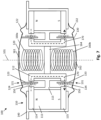
- FIG. 1 shows a sectional view of a loudspeaker 100.
- the sectional view is taken along a longitudinal axis 101 of the loudspeaker 100.
- Several of the below described components may have an axis of rotational symmetry, for example cylindrical or tubular components, and the axis of rotational symmetry of such a component may be aligned to the longitudinal axis 101.
- the loudspeaker 100 comprises a magnet assembly 110, a first diaphragm 120, a second diaphragm 130 and a basket 140.
- the magnet assembly 110, the first diaphragm 120, the second diaphragm 130 and at least parts of the basket 140 may each have a rotationally symmetrical shape with an axis of rotational symmetry aligned to the longitudinal axis 101.
- the first diaphragm 120 is arranged spaced apart from the second diaphragm 130.
- the first diaphragm 120 has a dome shape with an apex of the dome shape directing in an upward direction along the longitudinal axis 101 in FIG. 1 .
- the second diaphragm 130 has a dome shape with an apex of the dome shape directing in a downward direction along the longitudinal axis 101 in FIG. 1 .
- the first and second diaphragms 120, 130 may have essentially the same shape which may be rotationally symmetric with respect to the longitudinal axis 101.
- the basket 140 is provided between the first diaphragm 120 and the second diaphragm 130.
- the first diaphragm 120 may be coupled to the basket 140 via a surround 122
- the second diaphragm 130 may be coupled to the basket 140 via a surround 132.
- the surrounds 122 and 132 may be made of an elastic material, for example a rubber or plastics.
- the surrounds 122 and 132 enable a back and forth movement of the diaphragms 120 and 130, respectively, in the direction of the longitudinal axis 101.
- first and second diaphragms 120, 130 may have any other shape, for example a conical shape, a flat disk shape, a spherical shape, a dome shape, a horn shape, a funnel shape or a combination thereof.
- Each of the first and second diaphragms 120, 130 may be made from one piece or assembled from several pieces, which are made of the same or different materials.
- the basket 140 in combination with the first and second diaphragms 120, 130 and the surrounds 122, 132 may form a closed enclosure such that the volume inside the loudspeaker 100 is essentially decoupled from a surrounding.
- the volume inside the loudspeaker 100 may be coupled with surrounding volume, for example via openings in the basket 140.
- the magnet assembly 110 is mounted within the basket 140.
- the magnet assembly 110 comprises a magnet 111, a magnetic piece 112 and a spacer 113.
- the magnet 111, the magnetic piece 112 and the spacer 113 may each have a rotationally symmetrical shape with an axis of rotational symmetry aligned to the longitudinal axis 101.
- the spacer 113 is made of non-magnetic material, for example a paramagnetic, diamagnetic, or antiferromagnetic material.
- the spacer 113 may be made of plastics or a non-magnetic metal like aluminum.
- the magnet 111 may comprise a permanent magnet comprising ferromagnetic materials, for example iron, nickel, cobalt and/or neodymium. Additionally, the magnet 111 may be provided at each end in the direction of longitudinal axis 101 with a corresponding pole piece, i.e. a first pole piece 114 at an upper end in FIG. 1 and a second pole piece 115 at a lower end in FIG. 1 .
- the magnet 111 may be a hollow cylindrical magnet, a so-called ring magnet with a first magnetic polarity at the upper end in FIG. 1 , for example a north pole N, and a second magnetic polarity at the lower end in FIG. 1 , for example a south pole S.
- the first and second pole pieces 114, 115 may each have a washer shape with an axis of rotational symmetry aligned to the longitudinal axis 101.
- the first and second pole pieces 114 and 115 may be made of a ferromagnetic material, for example iron, nickel or cobalt such that they guide the magnetic field from the magnet 111 and may be considered to extend the poles of the magnet 111. Therefore, when the pole pieces 114 and 115 are present, in the following, the combination of magnet 111 and pole pieces 114, 115 will be referred to as magnet 111 also.
- the magnetic piece 112 may be made of ferromagnetic material, for example iron, nickel or cobalt, and may have a hollow cylindrical shape with an axis of rotational symmetry aligned to the longitudinal axis 101. As shown in FIG. 1 , an outer diameter of the magnetic piece 112 may be smaller than an inner diameter of the magnet 111.
- the spacer 113 couples the magnet 111 with the magnetic piece 112 such that at least at the upper and lower ends of the magnet 111 (including the pole pieces 114, 115) a gap 150 exists between the magnet 111 and the magnetic piece 112.
- the gap 150 may have a width in the radial direction of a few millimeters, for example in a range of 1 to 5 millimeters.
- the non-magnetic spacer may be arranged at a center of the gap 150 in a direction of the longitudinal axis 101.
- the spacer 113 defines the width of the gap 150 and assures a fixed arrangement of the magnet 111 with respect to the magnetic piece 112.
- a length of the magnet 111 and the magnetic piece 112 in the direction of the longitudinal axis 101 may be essentially the same and defines a length of the gap 150 in the direction of the longitudinal axis 101.
- the length of the gap 150 may be in the range of a few millimeters to a few centimeters, for example in a range of 10 to 50 millimeters. It is to be noticed that the gap 150 may be partly filled with the spacer 113. However, in particular the end sections of the gap 150, i.e. the upper end and the lower end in the direction of the longitudinal axis 101, may not be occupied by the spacer 113.
- a magnetic field generated by the magnet 111 is guided in radial direction through the gap 150 and the magnetic piece 112.
- a magnetic field 170 (for example B-field) may propagate from the north pole N at the upper end of the magnet 111 (if present, via the first pole piece 114) in a radial direction to the upper end of the magnetic piece 114 which guides the magnetic field 170 in the downward direction within the magnetic piece 114 to the lower end of the magnetic piece 114, where it propagates in a radial direction to the south pole S at the lower end of the magnet 111 (if present, via the second pole piece 115).
- the first voice coil 121 is provided which extends into the gap 150 at the upper end of the magnet assembly 110.
- the first voice coil 121 comprises a tubular carrier 123 on which a plurality of coil windings 124 are arranged.
- the carrier 123 may be made of a non-magnetic material, for example paper, aluminum or plastics, like polyimide, for example Kapton.
- An inner diameter of the carrier 123 is larger than an outer diameter of the magnetic piece 112.
- An outer diameter of the coil windings 124 is smaller than an inner diameter of the magnet 111.
- the voice coil 121 is movable in the direction of the longitudinal axis 101 in the up and down directions in FIG. 1 .
- a second voice coil 131 is provided which extends into the gap 150 at the lower end of the magnet assembly 110.
- the second voice coil 131 comprises a tubular carrier 133 on which a plurality of coil windings 134 are arranged.
- the carrier 133 may be made of non-magnetic material.
- An inner diameter of the carrier 133 is larger than an outer diameter of the magnetic piece 112.
- An outer diameter of the coil windings 134 is smaller than an inner diameter of the magnet 111.
- the voice coil 131 is movable in the direction of the longitudinal axis 101 in the up and down directions in FIG. 1 .
- the first and second diaphragms 120 and 130 can be deflected independently by energizing the first and second voice coils 124 and 134.
- only a single magnet assembly 110 is needed which provides a gap 150 with magnetic fields in which both voice coils 124 and 134 may be operated.
- the diaphragms 120, 130 may be controlled such that they are moving in opposite directions.
- an elastic element 160 may be provided between the first diaphragm 120 and the second diaphragm 130.
- a first end of the elastic element 160 is coupled to a center, for example the apex, of the first diaphragm 120.
- a second end of the elastic element 160 is coupled to a center, for example the apex, of the second diaphragm 130.
- a first fixation pad 161 may be arranged between the first end of the elastic element 160 and the first diaphragm 120
- a second fixation pad 162 may be arranged between the second end of the elastic element 160 and the second diaphragm 130.
- the elastic element 160 may comprise a spring element, made for example of metal or plastics.
- the elastic element 160 may comprise a plurality of springs or may comprise a cylindrical or bellows-shaped hollow element of elastic material, for example rubber or foam.
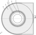
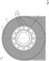
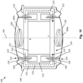
- FIG. 2 shows a sectional view along sectional plane A-A and FIGs. 3 and 4 show sectional views of various examples along sectional plane B-B.
- FIG. 2 shows a sectional view along sectional plane A-A of FIG. 1 .
- the sectional plane A-A extends perpendicular to the longitudinal axis 101.
- the basket 140 encloses the washer-shaped upper pole piece 114.
- the basket 140 in the illustrated example completely encloses the pole piece 114, this is only an example, and the basket may have cutouts or may comprise of a plurality of parts coupled to the pole pieces 114, 115 and the magnet 111, for example by gluing or press fitting.
- the basket 140 may comprise support structures, for example connecting straps, for mounting the loudspeaker 100 at an installation space, for example in a door, dashboard, ceiling, seat or headrest of a vehicle.
- the upper pole piece 114 has an inner opening in which the magnetic piece 112 is arranged with a gap 150 between an inner circumference of the upper pole piece 114 and an out circumference of the magnetic piece 112.
- the first voice coil 121 comprising the carrier 123 and the coil windings 124 is at least partly arranged in the gap 150.
- a gap between an outer circumference of the coil windings 124 and an inner circumference of the pole piece 114 is provided such that the voice coil 121 does not contact the pole piece 114 when moving up and down along the direction of the longitudinal axis 101.
- the magnetic piece 112 is arranged spaced apart from the inner circumference of the voice coil 121 such that the voice coil 121 does not contact the magnetic piece 112 when moving up and down along the direction of the longitudinal axis 101.
- the magnetic piece 112 may have a hollow cylindrical shape such that the cross section is a ring as shown in FIG. 2 .
- FIG. 3 shows a sectional view along sectional plane B-B of FIG. 1 .
- the sectional plane B-B extends perpendicular to the longitudinal axis 101 essentially in the center of the length of the magnet assembly 110.
- plane B-B extends through the spacer 113.
- the basket 140 encloses the washer-shaped pole pieces 114, 115 and the magnet 111.
- the magnet 111 may be glued or press fitted to the basket 140.
- the magnet 111 is a ring magnet, i.e. the magnet 111 has hollow cylindrical shape.
- the spacer 113 is mounted, for example by gluing or press fitting.
- the magnetic piece 112 is mounted, for example by gluing or press fitting. It is to be noticed that in FIGs. 2 and 3 the elastic element 160 is not shown for reasons of clarity.
- FIG. 4 shows a sectional view along sectional plane B-B of FIG. 1 of another example of implementing the spacer 113.
- the spacer 113 has cutouts thus forming an inner ring 113a, an out ring 113b and a plurality of spokes-like elements 113c.
- the inner ring 113a is in contact with the magnetic piece 112.
- the outer ring is in contact with the magnet 111 or the pole pieces 114, 115.
- the spoke-like elements 113c connect the inner ring 113a and the outer ring 113b.
- the inner ring 113a is connected via twelve spoke-like elements 113c to the outer ring 113b.
- the spacer 113 may have any other structure which allows a fixed arrangement of the magnetic piece 112 with respect to the magnet 111 and/or the pole pieces 114, 115.
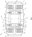
- FIG. 5 shows a further loudspeaker 100.
- the magnet assembly 110 is modified such that the magnet 111 is arranged inside the magnetic piece 112.
- the functionality of the loudspeaker 100 of FIG. 5 is essentially the same as the functionality of the loudspeaker 100 of FIG. 1 .
- the magnetic fields in the gap 150 for the first and second voice coils 121 and 131 are generated by a single magnet assembly 110, for example a single ring magnet 111 in connection with the magnetic piece 112.
- the spacer 113 keeps the magnet 111 in position with respect to the magnetic piece 112.
- FIG. 6 illustrates a loudspeaker 100 which essentially corresponds to the loudspeaker 100 of FIG. 1 .
- the optional first and second fixation pads 161 and 162 are not present in the loudspeaker 100 of FIG. 6 .
- the first end of the elastic element 160 is directly coupled to the center, for example the apex, of the first diaphragm 120
- the second end of the elastic element 160 is directly coupled to the center, for example the apex, of the second diaphragm 130, for example by gluing.
- FIG. 7 illustrates a further loudspeaker 100.
- the loudspeaker 100 of FIG. 7 comprises a support element 164 arranged within the magnetic piece 112 at a central position with respect to the longitudinal axis 101.
- the support element 164 may have a disk shape.
- An outer diameter of the support element 164 may be essentially the same as an inner diameter of the magnetic piece 112.
- the support element 164 may have a bar shape extending along an inner diameter of the magnetic piece 112.
- the support element 164 may be fixed within the magnetic piece 112 by press fitting or gluing.
- the loudspeaker 100 of FIG. 7 may be provided with a first elastic element 160a between the first diaphragm 120 and the support element 164, and with a second elastic element 160b between the second diaphragm 130 and the support element 164.
- a first end of the first elastic element 160a is coupled to a center, for example the apex, of the first diaphragm 120.
- a second end of the first elastic element 160a is coupled to one side of the support element 164.
- a first end of the second elastic element 160b is coupled to a center, for example the apex, of the second diaphragm 130.
- a second end of the second elastic element 160b is coupled to another side of the support element 164.
- a first fixation pad 161 may be arranged between the first end of the first elastic element 160a and the first diaphragm 120
- a second fixation pad 162 may be arranged between the first end of the second elastic element 160b and the second diaphragm 130.
- the first and second elastic elements 160a, 160b may each comprise a spring element, made for example of metal or plastics.
- the first and second elastic elements 160a, 160b may each comprise a plurality of springs or may comprise a cylindrical or bellows-shaped hollow element of elastic material, for example rubber or foam.
- the use of the two separate elastic elements 160a, 160b may utilize controlling the diaphragms 120, 130 independent from each other, e.g. deflection of diaphragm 120 does not influence deflection of diaphragm 130.
- FIG. 8 illustrates a loudspeaker 100.
- the loudspeaker of FIG. 8 comprises two elastic elements 160c and 160d.
- loudspeaker 100 of FIG. 8 does not comprise the support element 164.
- the loudspeaker 100 of FIG. 8 comprises the first elastic element 160c and the second elastic element 160d arranged along the longitudinal axis 101 and at least partially within the magnetic piece 112.
- a first end of the first elastic element 160c is coupled to a center, for example the apex, of the first diaphragm 120.
- a second end of the first elastic element 160a is coupled to the magnetic piece 112.
- the first elastic element 160c may comprise a spring.
- a spring wire at the second end of the first elastic element 160c may be formed as shown in FIG. 8 to contact the magnetic piece 112, for example at an upper base of the magnetic piece 112.
- a first end of the second elastic element 160d is coupled to a center, for example the apex, of the second diaphragm 130.
- a second end of the second elastic element 160d is coupled to the magnetic piece 112.
- the second elastic element 160d may comprise a spring.
- a spring wire at the second end of the second elastic element 160d may be formed as shown in FIG. 8 to contact the magnetic piece 112, for example at a lower base of the magnetic piece 112. The spring wires may be fixed to the magnetic piece 112 by gluing, welding or soldering.
- the elastic elements may provide guidance in the direction of the longitudinal axis 101.
- the elastic elements may inhibit or reduce a deflection of the corresponding diaphragm 120, 130 in the lateral direction, i.e. in a radial direction perpendicular to the longitudinal axis 101.
- the elastic elements enable deflection in the direction of the longitudinal axis 101 and provide a restoring force to the rest position for the corresponding diaphragm 120, 130.
- FIG. 9 shows a further loudspeaker 100 with a magnet assembly 110 in which the magnet 111 is arranged inside the magnetic piece 112.
- the functionality of the loudspeaker 100 of FIG. 9 is essentially the same as the functionality of the loudspeaker 100 of FIG. 1 .
- the magnetic fields in the gap 150 for the first and second voice coils 121 and 131 are generated by a single magnet assembly 110, for example a single disk magnet 111 in connection with disk shaped pole pieces 114, 115 and the magnetic piece 112.
- the spacer 113 keeps the magnet 111 in position with respect to the magnetic piece 112.
- a washer shaped support ring 167 is provided between the basket 140 and the magnetic piece 112 to keep the magnetic piece 112 in position with respect to the basket 140.
- Elastic elements 160i, 160j, 160k and 160m are provided between the support ring 167 and the first and second diaphragms 120, 130.
- elastic element 160i may be coupled between an upper side of the support ring 167 and the first diaphragm 120.
- elastic element 160k may be coupled between the upper side of the support ring 167 and the first diaphragm 120.
- elastic element 160j may be coupled between a lower side of the support ring 167 and the second diaphragm 130, and, at a diametric opposite position, the elastic element 160m may be coupled between the lower side of the support ring 167 and the second diaphragm 130.
- More than two elastic elements may be provided at each side of the support ring 167, for example three, four, six, eight or any other number.
- the elastic elements may be provided within an annular space delimited by the magnetic piece 112 and the basket 140.
- the elastic elements 160 may be arranged at a uniform distance from each other in the circumferential direction, i.e. evenly distributed in the circumferential direction.
- only one elastic element may be provided at each side of the support ring 167, or one elastic element may be provided extending from the first diaphragm 120 to the second diaphragm 130.
- the elastic element may comprise for example a spring with an inner diameter larger than an outer diameter of the magnetic piece 112, or the elastic element may comprise for example a tubular element or a bellows-shaped hollow element made of rubber or foam with an inner diameter larger than an outer diameter of the magnetic piece 112.
- the elastic element may surround the magnetic piece 112 in a circumferential direction of the magnetic piece 112.
- the elastic element may be arranged within the annular space between the magnetic piece 112 and the basket 140 and may contact the first and/or second diaphragms 120, 130 near an outer edge of the first and second diaphragms 120, 130, respectively.
- An axis of rotational symmetry of the elastic element may be aligned to the longitudinal axis 101.
- FIG. 10 shows a further loudspeaker 100 with a disk shaped magnet 111 in connection with first and second disk shaped pole pieces 114, 115 as loudspeaker 100 shown in FIG. 9 .
- the loudspeaker 100 of FIG. 10 comprises a first elastic element 160n between the first diaphragm 120 and the first pole piece 114 and a second elastic element 160p between the second diaphragm 130 and to the second pole piece 115.
- a first end of the first elastic element 160n is coupled to the first diaphragm 120.
- a second end of the first elastic element 160n is coupled to the first pole piece 114.
- a first end of the second elastic element 160p is coupled to the second diaphragm 130.
- a second end of the second elastic element 160p is coupled to the second pole piece 115.
- a first fixation pad may be arranged between the first end of the first elastic element 160n and the first diaphragm 120
- a second fixation pad may be arranged between the first end of the second elastic element 160p and the second diaphragm 130.
- the first and second elastic elements 160n, 160p may each comprise a spring element, made for example of metal or plastics.
- the first and second elastic elements 160n, 160p may each comprise a plurality of springs or may comprise a cylindrical or bellows-shaped hollow element of elastic material, for example rubber or foam.
- the use of the two separate elastic elements 160n, 160p may utilize controlling the diaphragms 120, 130 independent from each other, e.g. deflection of diaphragm 120 does not influence deflection of diaphragm 130.
Landscapes
- Physics & Mathematics (AREA)
- Engineering & Computer Science (AREA)
- Acoustics & Sound (AREA)
- Signal Processing (AREA)
- Audible-Bandwidth Dynamoelectric Transducers Other Than Pickups (AREA)
Priority Applications (3)
| Application Number | Priority Date | Filing Date | Title |
|---|---|---|---|
| EP21200094.7A EP4161096B1 (fr) | 2021-09-30 | 2021-09-30 | Haut-parleur |
| US17/943,529 US12250531B2 (en) | 2021-09-30 | 2022-09-13 | Loudspeaker |
| CN202211162586.2A CN115914955A (zh) | 2021-09-30 | 2022-09-23 | 扬声器 |
Applications Claiming Priority (1)
| Application Number | Priority Date | Filing Date | Title |
|---|---|---|---|
| EP21200094.7A EP4161096B1 (fr) | 2021-09-30 | 2021-09-30 | Haut-parleur |
Publications (2)
| Publication Number | Publication Date |
|---|---|
| EP4161096A1 true EP4161096A1 (fr) | 2023-04-05 |
| EP4161096B1 EP4161096B1 (fr) | 2025-05-28 |
Family
ID=78134813
Family Applications (1)
| Application Number | Title | Priority Date | Filing Date |
|---|---|---|---|
| EP21200094.7A Active EP4161096B1 (fr) | 2021-09-30 | 2021-09-30 | Haut-parleur |
Country Status (3)
| Country | Link |
|---|---|
| US (1) | US12250531B2 (fr) |
| EP (1) | EP4161096B1 (fr) |
| CN (1) | CN115914955A (fr) |
Families Citing this family (3)
| Publication number | Priority date | Publication date | Assignee | Title |
|---|---|---|---|---|
| US11812249B2 (en) * | 2019-02-07 | 2023-11-07 | Mayht Holding B.V. | In line damper bellows dual opposing driver speaker |
| JP7516415B2 (ja) * | 2019-04-11 | 2024-07-16 | ソノス・マイティ・ホールディングス・ベスローテン・フェンノートシャップ | リニアモータ磁石アセンブリ及びラウドスピーカユニット |
| DE102021200633B4 (de) * | 2021-01-25 | 2023-02-23 | Kaetel Systems Gmbh | Lautsprecher |
Citations (3)
| Publication number | Priority date | Publication date | Assignee | Title |
|---|---|---|---|---|
| FR2812751A1 (fr) * | 2000-08-01 | 2002-02-08 | Ecia Equip Composants Ind Auto | Dispositif acoustique pour une installation d'attenuation active de bruit |
| US6622817B1 (en) * | 1998-05-15 | 2003-09-23 | Harman Audio Electronic Systems Gmbh | Sound reproduction device working according to the bending wave principle |
| WO2015049218A1 (fr) * | 2013-10-04 | 2015-04-09 | Devialet | Dispositif de conversion électroacoustique ayant au moins deux haut-parleurs |
Family Cites Families (7)
| Publication number | Priority date | Publication date | Assignee | Title |
|---|---|---|---|---|
| FR2503516B1 (fr) * | 1981-04-01 | 1986-02-07 | Klein Siegfried | Haut-parleur electrodynamique omnidirectionnel pour les frequences basses et medium du spectre sonore |
| JP2002335597A (ja) * | 2001-05-09 | 2002-11-22 | Citizen Electronics Co Ltd | 複合スピーカー |
| WO2006089995A1 (fr) * | 2005-02-25 | 2006-08-31 | Nokia Corporation | Capteur audio |
| US10743097B1 (en) * | 2019-02-25 | 2020-08-11 | Resonado Inc. | Bidirectional speaker using bar magnets |
| GB2591223A (en) * | 2020-01-22 | 2021-07-28 | Gp Acoustics International Ltd | Loudspeakers |
| US20230388701A1 (en) * | 2020-10-14 | 2023-11-30 | Bose Corporation | Electroacoustic Transducer |
| KR102447285B1 (ko) * | 2020-12-24 | 2022-09-27 | 주식회사 알머스 | 이어폰용 스피커 유닛 |
-
2021
- 2021-09-30 EP EP21200094.7A patent/EP4161096B1/fr active Active
-
2022
- 2022-09-13 US US17/943,529 patent/US12250531B2/en active Active
- 2022-09-23 CN CN202211162586.2A patent/CN115914955A/zh active Pending
Patent Citations (3)
| Publication number | Priority date | Publication date | Assignee | Title |
|---|---|---|---|---|
| US6622817B1 (en) * | 1998-05-15 | 2003-09-23 | Harman Audio Electronic Systems Gmbh | Sound reproduction device working according to the bending wave principle |
| FR2812751A1 (fr) * | 2000-08-01 | 2002-02-08 | Ecia Equip Composants Ind Auto | Dispositif acoustique pour une installation d'attenuation active de bruit |
| WO2015049218A1 (fr) * | 2013-10-04 | 2015-04-09 | Devialet | Dispositif de conversion électroacoustique ayant au moins deux haut-parleurs |
Also Published As
| Publication number | Publication date |
|---|---|
| US12250531B2 (en) | 2025-03-11 |
| US20230097602A1 (en) | 2023-03-30 |
| EP4161096B1 (fr) | 2025-05-28 |
| CN115914955A (zh) | 2023-04-04 |
Similar Documents
| Publication | Publication Date | Title |
|---|---|---|
| US12250531B2 (en) | Loudspeaker | |
| US20230188898A1 (en) | Loudspeaker | |
| US8073186B2 (en) | Loudspeaker | |
| KR101224242B1 (ko) | 스피커 장치 | |
| US7236607B2 (en) | Loudspeaker with a first and a second diaphragm body | |
| JPH11275678A (ja) | スピーカ装置 | |
| US9538291B2 (en) | Speaker | |
| KR20060049563A (ko) | 동전형 여진기 및 이를 이용한 스피커 | |
| US20120039494A1 (en) | Loudspeakers | |
| CN110972042A (zh) | 双线圈差分驱动触觉换能器 | |
| US20250016497A1 (en) | Speaker device | |
| CN110268724A (zh) | 扬声器 | |
| US12395786B2 (en) | Loudspeaker | |
| US20030031337A1 (en) | Loudspeaker with a three-dimensional diaphragm | |
| JP7437002B2 (ja) | 音響パネルアセンブリ | |
| WO2008059597A1 (fr) | Haut-parleur | |
| US20250193608A1 (en) | Hybrid sound radiation device for vibrating a heavy-weight rigid plate at audio frequencies | |
| EP4120694A1 (fr) | Unité de commande pour un haut-parleur | |
| EP4535825A1 (fr) | Haut-parleur à hauteur réduite | |
| WO2024253529A1 (fr) | Transducteur | |
| CN119605190A (zh) | 低音扬声器系统 | |
| KR20160048490A (ko) | 다수의 동축 배열 진동판을 포함하는 선형 배열 음향 변환기 |
Legal Events
| Date | Code | Title | Description |
|---|---|---|---|
| PUAI | Public reference made under article 153(3) epc to a published international application that has entered the european phase |
Free format text: ORIGINAL CODE: 0009012 |
|
| STAA | Information on the status of an ep patent application or granted ep patent |
Free format text: STATUS: THE APPLICATION HAS BEEN PUBLISHED |
|
| AK | Designated contracting states |
Kind code of ref document: A1 Designated state(s): AL AT BE BG CH CY CZ DE DK EE ES FI FR GB GR HR HU IE IS IT LI LT LU LV MC MK MT NL NO PL PT RO RS SE SI SK SM TR |
|
| STAA | Information on the status of an ep patent application or granted ep patent |
Free format text: STATUS: REQUEST FOR EXAMINATION WAS MADE |
|
| 17P | Request for examination filed |
Effective date: 20230927 |
|
| RBV | Designated contracting states (corrected) |
Designated state(s): AL AT BE BG CH CY CZ DE DK EE ES FI FR GB GR HR HU IE IS IT LI LT LU LV MC MK MT NL NO PL PT RO RS SE SI SK SM TR |
|
| GRAP | Despatch of communication of intention to grant a patent |
Free format text: ORIGINAL CODE: EPIDOSNIGR1 |
|
| STAA | Information on the status of an ep patent application or granted ep patent |
Free format text: STATUS: GRANT OF PATENT IS INTENDED |
|
| GRAS | Grant fee paid |
Free format text: ORIGINAL CODE: EPIDOSNIGR3 |
|
| RIC1 | Information provided on ipc code assigned before grant |
Ipc: H04R 1/40 20060101ALN20250320BHEP Ipc: H04R 7/12 20060101ALN20250320BHEP Ipc: H04R 9/04 20060101ALI20250320BHEP Ipc: H04R 9/02 20060101AFI20250320BHEP |
|
| GRAA | (expected) grant |
Free format text: ORIGINAL CODE: 0009210 |
|
| STAA | Information on the status of an ep patent application or granted ep patent |
Free format text: STATUS: THE PATENT HAS BEEN GRANTED |
|
| INTG | Intention to grant announced |
Effective date: 20250328 |
|
| RIC1 | Information provided on ipc code assigned before grant |
Ipc: H04R 1/40 20060101ALN20250324BHEP Ipc: H04R 7/12 20060101ALN20250324BHEP Ipc: H04R 9/04 20060101ALI20250324BHEP Ipc: H04R 9/02 20060101AFI20250324BHEP |
|
| AK | Designated contracting states |
Kind code of ref document: B1 Designated state(s): AL AT BE BG CH CY CZ DE DK EE ES FI FR GB GR HR HU IE IS IT LI LT LU LV MC MK MT NL NO PL PT RO RS SE SI SK SM TR |
|
| REG | Reference to a national code |
Ref country code: GB Ref legal event code: FG4D |
|
| REG | Reference to a national code |
Ref country code: CH Ref legal event code: EP |
|
| REG | Reference to a national code |
Ref country code: IE Ref legal event code: FG4D Ref country code: DE Ref legal event code: R096 Ref document number: 602021031374 Country of ref document: DE |
|
| REG | Reference to a national code |
Ref country code: NL Ref legal event code: MP Effective date: 20250528 |
|
| PG25 | Lapsed in a contracting state [announced via postgrant information from national office to epo] |
Ref country code: FI Free format text: LAPSE BECAUSE OF FAILURE TO SUBMIT A TRANSLATION OF THE DESCRIPTION OR TO PAY THE FEE WITHIN THE PRESCRIBED TIME-LIMIT Effective date: 20250528 Ref country code: ES Free format text: LAPSE BECAUSE OF FAILURE TO SUBMIT A TRANSLATION OF THE DESCRIPTION OR TO PAY THE FEE WITHIN THE PRESCRIBED TIME-LIMIT Effective date: 20250528 |
|
| PGFP | Annual fee paid to national office [announced via postgrant information from national office to epo] |
Ref country code: DE Payment date: 20250820 Year of fee payment: 5 |
|
| REG | Reference to a national code |
Ref country code: LT Ref legal event code: MG9D |
|
| PG25 | Lapsed in a contracting state [announced via postgrant information from national office to epo] |
Ref country code: NO Free format text: LAPSE BECAUSE OF FAILURE TO SUBMIT A TRANSLATION OF THE DESCRIPTION OR TO PAY THE FEE WITHIN THE PRESCRIBED TIME-LIMIT Effective date: 20250828 Ref country code: GR Free format text: LAPSE BECAUSE OF FAILURE TO SUBMIT A TRANSLATION OF THE DESCRIPTION OR TO PAY THE FEE WITHIN THE PRESCRIBED TIME-LIMIT Effective date: 20250829 |
|
| PG25 | Lapsed in a contracting state [announced via postgrant information from national office to epo] |
Ref country code: NL Free format text: LAPSE BECAUSE OF FAILURE TO SUBMIT A TRANSLATION OF THE DESCRIPTION OR TO PAY THE FEE WITHIN THE PRESCRIBED TIME-LIMIT Effective date: 20250528 Ref country code: PL Free format text: LAPSE BECAUSE OF FAILURE TO SUBMIT A TRANSLATION OF THE DESCRIPTION OR TO PAY THE FEE WITHIN THE PRESCRIBED TIME-LIMIT Effective date: 20250528 |
|
| PG25 | Lapsed in a contracting state [announced via postgrant information from national office to epo] |
Ref country code: BG Free format text: LAPSE BECAUSE OF FAILURE TO SUBMIT A TRANSLATION OF THE DESCRIPTION OR TO PAY THE FEE WITHIN THE PRESCRIBED TIME-LIMIT Effective date: 20250528 |
|
| PGFP | Annual fee paid to national office [announced via postgrant information from national office to epo] |
Ref country code: GB Payment date: 20250820 Year of fee payment: 5 |
|
| PG25 | Lapsed in a contracting state [announced via postgrant information from national office to epo] |
Ref country code: HR Free format text: LAPSE BECAUSE OF FAILURE TO SUBMIT A TRANSLATION OF THE DESCRIPTION OR TO PAY THE FEE WITHIN THE PRESCRIBED TIME-LIMIT Effective date: 20250528 |
|
| PG25 | Lapsed in a contracting state [announced via postgrant information from national office to epo] |
Ref country code: RS Free format text: LAPSE BECAUSE OF FAILURE TO SUBMIT A TRANSLATION OF THE DESCRIPTION OR TO PAY THE FEE WITHIN THE PRESCRIBED TIME-LIMIT Effective date: 20250828 |
|
| PG25 | Lapsed in a contracting state [announced via postgrant information from national office to epo] |
Ref country code: IS Free format text: LAPSE BECAUSE OF FAILURE TO SUBMIT A TRANSLATION OF THE DESCRIPTION OR TO PAY THE FEE WITHIN THE PRESCRIBED TIME-LIMIT Effective date: 20250928 |
|
| PG25 | Lapsed in a contracting state [announced via postgrant information from national office to epo] |
Ref country code: LV Free format text: LAPSE BECAUSE OF FAILURE TO SUBMIT A TRANSLATION OF THE DESCRIPTION OR TO PAY THE FEE WITHIN THE PRESCRIBED TIME-LIMIT Effective date: 20250528 |
|
| REG | Reference to a national code |
Ref country code: AT Ref legal event code: MK05 Ref document number: 1799342 Country of ref document: AT Kind code of ref document: T Effective date: 20250528 |
|
| PG25 | Lapsed in a contracting state [announced via postgrant information from national office to epo] |
Ref country code: AT Free format text: LAPSE BECAUSE OF FAILURE TO SUBMIT A TRANSLATION OF THE DESCRIPTION OR TO PAY THE FEE WITHIN THE PRESCRIBED TIME-LIMIT Effective date: 20250528 Ref country code: DK Free format text: LAPSE BECAUSE OF FAILURE TO SUBMIT A TRANSLATION OF THE DESCRIPTION OR TO PAY THE FEE WITHIN THE PRESCRIBED TIME-LIMIT Effective date: 20250528 Ref country code: SM Free format text: LAPSE BECAUSE OF FAILURE TO SUBMIT A TRANSLATION OF THE DESCRIPTION OR TO PAY THE FEE WITHIN THE PRESCRIBED TIME-LIMIT Effective date: 20250528 |
|
| PG25 | Lapsed in a contracting state [announced via postgrant information from national office to epo] |
Ref country code: CZ Free format text: LAPSE BECAUSE OF FAILURE TO SUBMIT A TRANSLATION OF THE DESCRIPTION OR TO PAY THE FEE WITHIN THE PRESCRIBED TIME-LIMIT Effective date: 20250528 |
|
| PG25 | Lapsed in a contracting state [announced via postgrant information from national office to epo] |
Ref country code: EE Free format text: LAPSE BECAUSE OF FAILURE TO SUBMIT A TRANSLATION OF THE DESCRIPTION OR TO PAY THE FEE WITHIN THE PRESCRIBED TIME-LIMIT Effective date: 20250528 |
|
| PG25 | Lapsed in a contracting state [announced via postgrant information from national office to epo] |
Ref country code: SK Free format text: LAPSE BECAUSE OF FAILURE TO SUBMIT A TRANSLATION OF THE DESCRIPTION OR TO PAY THE FEE WITHIN THE PRESCRIBED TIME-LIMIT Effective date: 20250528 |
|
| PG25 | Lapsed in a contracting state [announced via postgrant information from national office to epo] |
Ref country code: IT Free format text: LAPSE BECAUSE OF FAILURE TO SUBMIT A TRANSLATION OF THE DESCRIPTION OR TO PAY THE FEE WITHIN THE PRESCRIBED TIME-LIMIT Effective date: 20250528 |
|
| REG | Reference to a national code |
Ref country code: DE Ref legal event code: R097 Ref document number: 602021031374 Country of ref document: DE |
|
| PG25 | Lapsed in a contracting state [announced via postgrant information from national office to epo] |
Ref country code: RO Free format text: LAPSE BECAUSE OF FAILURE TO SUBMIT A TRANSLATION OF THE DESCRIPTION OR TO PAY THE FEE WITHIN THE PRESCRIBED TIME-LIMIT Effective date: 20250528 |
|
| PLBE | No opposition filed within time limit |
Free format text: ORIGINAL CODE: 0009261 |
|
| STAA | Information on the status of an ep patent application or granted ep patent |
Free format text: STATUS: NO OPPOSITION FILED WITHIN TIME LIMIT |
|
| REG | Reference to a national code |
Ref country code: CH Ref legal event code: L10 Free format text: ST27 STATUS EVENT CODE: U-0-0-L10-L00 (AS PROVIDED BY THE NATIONAL OFFICE) Effective date: 20260409 |