EP4162330B1 - Sicherheitssteuerungssystem und verfahren zum ausführen einer sicherheitsfunktion - Google Patents
Sicherheitssteuerungssystem und verfahren zum ausführen einer sicherheitsfunktion Download PDFInfo
- Publication number
- EP4162330B1 EP4162330B1 EP21728532.9A EP21728532A EP4162330B1 EP 4162330 B1 EP4162330 B1 EP 4162330B1 EP 21728532 A EP21728532 A EP 21728532A EP 4162330 B1 EP4162330 B1 EP 4162330B1
- Authority
- EP
- European Patent Office
- Prior art keywords
- safety
- automation system
- controller
- function
- safety controller
- Prior art date
- Legal status (The legal status is an assumption and is not a legal conclusion. Google has not performed a legal analysis and makes no representation as to the accuracy of the status listed.)
- Active
Links
Images


Classifications
-
- G—PHYSICS
- G05—CONTROLLING; REGULATING
- G05B—CONTROL OR REGULATING SYSTEMS IN GENERAL; FUNCTIONAL ELEMENTS OF SUCH SYSTEMS; MONITORING OR TESTING ARRANGEMENTS FOR SUCH SYSTEMS OR ELEMENTS
- G05B19/00—Program-control systems
- G05B19/02—Program-control systems electric
- G05B19/04—Program control other than numerical control, i.e. in sequence controllers or logic controllers
- G05B19/042—Program control other than numerical control, i.e. in sequence controllers or logic controllers using digital processors
- G05B19/0428—Safety, monitoring
-
- B—PERFORMING OPERATIONS; TRANSPORTING
- B25—HAND TOOLS; PORTABLE POWER-DRIVEN TOOLS; MANIPULATORS
- B25J—MANIPULATORS; CHAMBERS PROVIDED WITH MANIPULATION DEVICES
- B25J13/00—Controls for manipulators
- B25J13/06—Control stands, e.g. consoles, switchboards
-
- B—PERFORMING OPERATIONS; TRANSPORTING
- B25—HAND TOOLS; PORTABLE POWER-DRIVEN TOOLS; MANIPULATORS
- B25J—MANIPULATORS; CHAMBERS PROVIDED WITH MANIPULATION DEVICES
- B25J9/00—Program-controlled manipulators
- B25J9/16—Program controls
- B25J9/1674—Program controls characterised by safety, monitoring, diagnostic
-
- G—PHYSICS
- G05—CONTROLLING; REGULATING
- G05B—CONTROL OR REGULATING SYSTEMS IN GENERAL; FUNCTIONAL ELEMENTS OF SUCH SYSTEMS; MONITORING OR TESTING ARRANGEMENTS FOR SUCH SYSTEMS OR ELEMENTS
- G05B19/00—Program-control systems
- G05B19/02—Program-control systems electric
- G05B19/18—Numerical control [NC], i.e. automatically operating machines, in particular machine tools, e.g. in a manufacturing environment, so as to execute positioning, movement or co-ordinated operations by means of program data in numerical form
- G05B19/409—Numerical control [NC], i.e. automatically operating machines, in particular machine tools, e.g. in a manufacturing environment, so as to execute positioning, movement or co-ordinated operations by means of program data in numerical form characterised by using manual data input [MDI] or by using control panel, e.g. controlling functions with the panel; characterised by control panel details or by setting parameters
-
- G—PHYSICS
- G05—CONTROLLING; REGULATING
- G05B—CONTROL OR REGULATING SYSTEMS IN GENERAL; FUNCTIONAL ELEMENTS OF SUCH SYSTEMS; MONITORING OR TESTING ARRANGEMENTS FOR SUCH SYSTEMS OR ELEMENTS
- G05B2219/00—Program-control systems
- G05B2219/20—Pc systems
- G05B2219/23—Pc programming
- G05B2219/23258—GUI graphical user interface, icon, function bloc editor, labview
-
- G—PHYSICS
- G05—CONTROLLING; REGULATING
- G05B—CONTROL OR REGULATING SYSTEMS IN GENERAL; FUNCTIONAL ELEMENTS OF SUCH SYSTEMS; MONITORING OR TESTING ARRANGEMENTS FOR SUCH SYSTEMS OR ELEMENTS
- G05B2219/00—Program-control systems
- G05B2219/20—Pc systems
- G05B2219/24—Pc safety
- G05B2219/24091—Display indication out of order, alarm indication
-
- G—PHYSICS
- G05—CONTROLLING; REGULATING
- G05B—CONTROL OR REGULATING SYSTEMS IN GENERAL; FUNCTIONAL ELEMENTS OF SUCH SYSTEMS; MONITORING OR TESTING ARRANGEMENTS FOR SUCH SYSTEMS OR ELEMENTS
- G05B2219/00—Program-control systems
- G05B2219/20—Pc systems
- G05B2219/24—Pc safety
- G05B2219/24093—Display, show place of error, fault
-
- G—PHYSICS
- G05—CONTROLLING; REGULATING
- G05B—CONTROL OR REGULATING SYSTEMS IN GENERAL; FUNCTIONAL ELEMENTS OF SUCH SYSTEMS; MONITORING OR TESTING ARRANGEMENTS FOR SUCH SYSTEMS OR ELEMENTS
- G05B2219/00—Program-control systems
- G05B2219/30—Nc systems
- G05B2219/31—From computer integrated manufacturing till monitoring
- G05B2219/31469—Graphical display of process as function of detected alarm signals
-
- G—PHYSICS
- G05—CONTROLLING; REGULATING
- G05B—CONTROL OR REGULATING SYSTEMS IN GENERAL; FUNCTIONAL ELEMENTS OF SUCH SYSTEMS; MONITORING OR TESTING ARRANGEMENTS FOR SUCH SYSTEMS OR ELEMENTS
- G05B2219/00—Program-control systems
- G05B2219/30—Nc systems
- G05B2219/39—Robotics, robotics to robotics hand
- G05B2219/39001—Robot, manipulator control
-
- G—PHYSICS
- G05—CONTROLLING; REGULATING
- G05B—CONTROL OR REGULATING SYSTEMS IN GENERAL; FUNCTIONAL ELEMENTS OF SUCH SYSTEMS; MONITORING OR TESTING ARRANGEMENTS FOR SUCH SYSTEMS OR ELEMENTS
- G05B2219/00—Program-control systems
- G05B2219/30—Nc systems
- G05B2219/39—Robotics, robotics to robotics hand
- G05B2219/39447—Dead man switch
-
- G—PHYSICS
- G05—CONTROLLING; REGULATING
- G05B—CONTROL OR REGULATING SYSTEMS IN GENERAL; FUNCTIONAL ELEMENTS OF SUCH SYSTEMS; MONITORING OR TESTING ARRANGEMENTS FOR SUCH SYSTEMS OR ELEMENTS
- G05B2219/00—Program-control systems
- G05B2219/30—Nc systems
- G05B2219/50—Machine tool, machine tool null till machine tool work handling
- G05B2219/50198—Emergency stop
Definitions
- the present invention relates to a safety control system and a method for carrying out a safety function for at least one automation system component, wherein the safety control system has a safety controller and one or more safety input means, and wherein a display device is arranged on each safety input means and the display device is configured to visualize an effective range of the safety function depending on a predetermined safety configuration of the safety controller when the automation system component is connected to the safety controller.
- the applicable safety guidelines e.g. DIN EN ISO 10218-22012-06
- a safety function e.g. an emergency stop function.
- appropriate safety buttons have been used for this purpose, based on the standards, usually red emergency stop buttons with a yellow housing as a background. In some versions, this emergency stop button or its housing can also be actively illuminated to make it more visible in poor lighting conditions within the system.
- red emergency stop buttons with a yellow housing as a background.
- this emergency stop button or its housing can also be actively illuminated to make it more visible in poor lighting conditions within the system.
- it is known to use different emergency stop buttons for different effective areas of an emergency stop function in order to activate a corresponding emergency stop function only for the affected effective area. This is to ensure that when an emergency stop button is pressed, the entire system is not always put into an emergency stop state.
- the emergency stop buttons have so far been marked with labels or markings to indicate the effective range of the triggered emergency stop function.
- Coordinated robot networks made up of several robots can also be changed during runtime depending on the work step.
- the robot network (R 1 + R 2 ) and the robot network (R 2 + R 3 ) represent different effective areas of a safety function of a safety controller at different times.
- Another example of these robot networks would be the station change of a mobile robot platform in a matrix-like production concept.
- the mobile robot platform usually operates autonomously in the production plant and, together with a processing station, which can itself have one or more processing robots, forms a temporary robot network during the processing in the station.
- the WO 2020/087098 A1 discloses a method for operating a machine control system, wherein a mobile hand-held control device with an emergency stop actuation element is provided for this purpose and can be carried by an operator.
- the machine control and the hand-held control device are designed to display an image of the machine control system and to display the area(s) of action of at least one emergency stop actuating element by means of a display.
- the EP 3 418 825 A1 discloses a system with a safety control that can interrupt the power supply to an automation system or bring it into a safe state by means of an operator's input.
- the system also includes an emergency stop switch that can be operated by the operator and a user interface connected to it.
- the EP 2 098 926 A1 discloses a method for programming or configuring a safety controller and a connection module which has an input for a sensor or an output for an actuator, wherein sensors or actuators are selected via a graphical user interface and assigned to inputs or outputs of the connection module.
- the EP 1 716 982 A1 discloses an industrial robot with a control unit and an input means, wherein the control unit and the input means can communicate wirelessly for program operation of the industrial robot. To couple the control unit and the input means, they are connected and coupled in close proximity to one another by means of a temporary auxiliary connection.
- the object of the present invention is to provide a safety control system and to specify a method to improve the safety of the plant operator or commissioning engineer when triggering a safety function within an automation system.
- a safety control system for executing a safety function for at least one automation system component, wherein the safety control system has a safety controller and one or more safety input means, and wherein the execution of the safety function is triggered by actuating one of the safety input means.
- a display device is arranged on each of the safety input means, which is further configured to visualize the effective range of the safety function depending on a predetermined safety configuration of the safety controller when the automation system component is connected to the safety controller.
- a safety controller in the sense of the invention can be designed as an independent unit or as part of an automation controller, e.g. as a subcomponent of the automation system or as a higher-level system controller.
- the safety controller preferably has a processor unit as well as signal inputs and signal outputs.
- the processor unit communicates with the automation system components and safety input means that are connected to the safety controller.
- An automation system is understood to be a production system as it is known from industrial practice.
- An automation system can consist of one or more automation system components that operate at least partially automatically, e.g. manipulators, in particular industrial robots, or other handling units, such as conveyor systems, process stations, etc.
- Automation system components that cooperate with one another can form a network, at least temporarily, with the network carrying out a common task in accordance with a system or application program.
- a safety input device can be a safety button, preferably designed in safe technology, e.g. an emergency stop button, which is connected to a safe input of the Safety controller is connected.
- a safety input device When the safety input device is operated, a safe input of the safety controller is switched and a safety function is then triggered by the safety controller.
- one or more safety input devices distributed throughout the system can be used, each of which can be operated by the system operator and each individually triggers the assigned safety function. Distributing several such safety input devices within the automation system has the advantage that the underlying safety function can thus be triggered in several places.
- a safety function in the sense of the invention represents a predetermined movement reaction of the automation system component, which is triggered directly by the signal from the safety controller or by a movement control influenced by the signal.
- a movement reaction can, for example, be a complete standstill or just a reduction in the movement speed of the automation system component to a safe speed in order to minimize the risk of injury to the system operator.
- the safety function of a manipulator, particularly an industrial robot, that is usually triggered by an emergency stop button is the emergency stop function.
- the movement reaction in this case is to bring the affected automation system component to a complete standstill as quickly as possible.
- the emergency stop can be generated, for example, by means of the safety control by immediately switching off the power to the drives and simultaneously applying the mechanical brakes of the automation system component, the so-called "stop category 0".
- the emergency stop function can bring the manipulator affected by the safety function to a standstill by the movement control using electrical and/or mechanical brakes can be non-track-compliant ("Stop Category 1") or track-compliant ("Stop Category 2").
- the effective range of the safety function is the automation system component influenced by the safety function at the time of triggering by the safety input means.
- the effective range is specified by a safety configuration of the safety controller and can change during commissioning or when reconfiguring an automation system or during its operation.
- the safety configuration in the sense of the invention is a grouping of automation system components specified by the system operator or commissioning engineer, which interact with each other in particular temporarily or depending on a program or application sequence.
- the safety configuration thus indicates which automation system components are in the effective range of a safety function at a specific point in time in the program sequence.
- the display device is a unit arranged on the safety input means for visualizing the current effective range of the safety function depending on a predetermined safety configuration of the safety control.
- the display device can be an integral part of the safety input means or, in another embodiment, can be arranged in the immediate vicinity of the safety input means.
- the visualization can either be carried out by the display device alone or in conjunction with other means.
- the automation system components comprise local safety controllers, wherein the local safety controllers can represent sub-elements of the safety controller of the safety control system. This is particularly preferred if the automation system components are connected to the safety controller of the safety control system at a specific time.
- the proposed safety controller can function as a central safety controller, wherein the central safety controller is connected to the local safety controllers of the automation system components. If a local safety controller of an automation system component is removed from the network of the central and local safety controllers, the remote local safety controller no longer operates in the network of the central and remaining local safety controllers. However, the remote local safety controller is still able to influence the still functional automation system component to which it is connected. For example, the remote local safety controller can shut down the automation system component for which it is responsible.
- the local safety controller can comprise a safety input means, whereby this safety input means present on the local safety controller can be a safety input means of the proposed safety control system. This is particularly preferred in the sense of the invention if the corresponding local safety controller is connected to the safety controller of the safety control system at a specific point in time.
- a safety input means provided on the local safety controller can preferably also be referred to as a local safety input means in the sense of the invention.
- the display device can be designed as a screen which is set up to visualize the effective range of the safety function by displaying a graphic representation of the automation system component connected to the safety controller.
- the screen can preferably be designed as a touch display or E-Ink screen on which the graphic representation of the automation system component can be visualized.
- the graphic representation of the automation system component connected to the safety controller can be a 2D or 3D representation of the system, e.g. a sketchy drawing, a CAD model or an image previously taken of the automation system component.
- the display can even be influenced interactively, e.g. the size of the displayed automation system component can be reduced or enlarged as required or, if necessary, messages from the safety controller can be displayed or confirmed by the system operator.
- the display device in the present invention is a color-changeable first signaling means.
- the signaling means can be a luminous-active light source or a luminous-passive display means.
- the luminous-active light source can further comprise one or more light bulbs, light-emitting diodes or luminous surfaces.
- the use of light-emitting diodes represents a cost-effective and easy-to-attach visualization option to the safety input means or to its button, housing or holder. Due to their greater beam effect, luminous surfaces offer advantages over light-emitting diodes, as they can be recognized more easily.
- a luminous-passive display means can be a color-changeable, in particular switchable, display whose state differs in the visual representation of at least two colors, for example an E-Ink screen.
- the color-changeability of the signaling means offers the system operator the possibility of easily distinguishing the safety input means from a safety input means of another safety control system that is marked in a different color.
- the second signaling means can be luminous-active lamps or luminous-passive display means like the first signaling means.
- the luminous-active lamps can also comprise one or more light bulbs, light-emitting diodes or luminous surfaces. In the sense of the invention, the use of lamps that are already provided on robots for other purposes is particularly preferred, such as luminous rings on or in the robot structure or signal lights on mobile robot platforms.
- Luminous-passive display means can again be color-changeable, in particular switchable displays, the state of which differs in the visual representation of at least two colors, for example an E-Ink screen.
- luminous-passive display means can also be light reflectors, such as mirrors or prisms.
- the color-changeability of the second signaling means offers the possibility of distinguishing the automation system component from automation system components marked in a different color.
- the use of light reflectors makes it possible to install projectors at a suitable location in the automation system, which illuminate the light reflectors with light of the desired color. This offers the advantage that no additional luminous lamps need to be attached to the automation system components, but they can be passively illuminated.
- the first and one or more second signaling devices visualize the effective range of the safety function by the first signaling device and the one or more second signaling devices having a matching color.
- This matching color makes it particularly easy for a system operator to establish a match between the safety input device to be used and the automation system component marked in the same color in order to influence the right part of the system with a safety function in an emergency, e.g. to shut it down completely.
- a further aspect of the invention relates to a method for executing a safety function for at least one automation system component by means of a safety controller and one or more safety input means, wherein a display device is arranged on the safety input means.
- the method comprises the steps of specifying a safety configuration of the safety controller and determining the automation system component that is connected to the safety controller.
- the method further comprises the step of visualizing the effective range of the safety function on or by a display device of the safety input means depending on the specified safety configuration.
- the execution of the safety function is triggered by actuating one of the safety input means.
- the safety configuration of the safety controller can be specified by the system operator or the commissioning engineer.
- the safety configuration can be used to store in the safety controller which of the automation system components are in the effective range of a safety function or are influenced by it at a specific point in time during the program run.
- the automation system component that is connected to the safety control can be determined either by an independent processor unit of the safety control, a sub-unit of an automation control or a higher-level system control, whereby a data connection, in particular using safe technology, is used to communicate with the parts of the automation system, in particular their Components whose presence is checked.
- data packets can be sent once or repeatedly, preferably periodically, by the safety controller to the automation system component and, if a response is received, the presence of the responding automation system component is confirmed.
- the current, particularly safety-relevant, effective range of the safety function is then visualized using the display device in the visualization step.
- the display device can be a screen, in particular a touch display or E-Ink screen.
- the effective range of the safety function is visualized by displaying a graphic representation, e.g. as an image of the automation system component connected to the safety controller on the screen. This representation enables the system operator to see the safety-relevant effective range in the automation system at first glance at the screen.
- the display device can be a color-changeable first signaling device.
- the first signaling device can be a light-active illuminant, which in particular comprises one or more light bulbs, light-emitting diodes or luminous surfaces.
- the first signaling device can be a light-passive display device, which comprises a color-changeable, in particular switchable display.
- one or more color-changeable second signaling devices can be assigned to the automation system component.
- the second signaling devices can be light-active illuminants, which in particular comprise one or more light bulbs, light-emitting diodes, luminous surfaces.
- the second signaling devices can also be light-passive display devices, which comprise color-changeable, in particular switchable displays, or are light reflectors, such as mirrors or prisms.
- the step of visualizing the effective range of the safety function can be carried out by a color match of the first and second signaling devices. This visualization is a cost-effective The plant operator is able to identify, through purely visual perception, the automation system components that are currently influenced by the safety function of the safety input device.
- the method allows the visualization by the display device to be updated depending on the specified safety configuration of the safety controller when the automation system component is connected to the safety controller or disconnected from the safety controller.
- the safety controller can monitor the activation or deactivation of its signal inputs and signal outputs and generate a signal to update the display device, in particular when the data connection to individual automation system components is established or when it breaks down.
- Activation or deactivation can be carried out actively by physically connecting the individual components of the automation system to the safety controller. In this way, wired or wireless communication can be established between the component and the safety controller.
- this connection may already exist and the data connection is activated or deactivated automatically in the automation system's sequence program, depending on the time or process. This can take place by digitally switching a signal input or signal output in the automation system component or a program sequence control or system control connected between the automation system component and the safety controller.
- the safety controller changes the state of the display device depending on the specified safety configuration of the safety controller.
- the graphic representation i.e. the image displayed, can change in such a way that the effective range of the safety function is shown precisely. If a new automation system component is now added to the existing automation system component and this is part of the effective range according to the specified safety configuration, a new image is shown on the screen, which next to the already displayed automation system component shows the new automation system component.
- the safety controller can set the color of the signaling device on the new automation system component so that it now matches the color of the signaling device on the safety input device in order to visualize the belonging to the effective range of the safety function, with the same goal of precisely displaying the effective range of the safety function.
- the display device of the safety input device is not currently showing an image, or if the lights on the safety input device are not lit, this signals to the system operator that this safety input device does not currently have a safety function. If the safety input device is color-coded and the color does not match the signaling devices of an existing automation system component, this signals to the system operator that this safety input device cannot trigger a suitable safety function for the existing automation system component. The same applies if the screen of the safety input device shows a different image than that of the existing automation system component. The system operator can only influence the system safely, e.g. shut it down, if the color of the signaling devices on the safety input device and the signaling devices in the affected automation system components, or only if the automation system components that the system operator wants to influence are displayed on the screen of the safety input device.
- Fig. 1 shows a schematic representation of a safety control system (10) not according to the invention.
- the safety control system (10) comprises a safety controller (12), a safety input means (14), which can be designed as a safety button, and a display device (16), which can be designed as a screen.
- the screen (16) is clearly visible to the system operator, in particular integrated on the top in the housing of the safety button (14).
- the safety button (14) and the screen (16) are integral components of an input device of the automation system.
- One or more automation system components (18, 20) are usually commanded during commissioning using such an input device in order to create a system program.
- the screen (16) of this automation system input device serves as a status display of the current program sequence.
- the safety controller (12) can in particular be part of an automation system controller (22), which at least partially controls the automation system.
- the system operator or commissioning engineer stores in the safety controller (12) which of the automation system components are in the effective range of a safety function or are influenced by it at a specific point in time in the program sequence.
- the safety controller (12) can function as a central safety controller and interact with the individual local safety controllers of the individual automation system components (18, 20) if the corresponding automation system component (18, 20) is connected to a central safety controller (12).
- the configuration of the local safety controller is integrated into the safety configuration of the central safety controller (12) or taken into account by it.
- the automation system components (18, 20) can in particular be manipulators, particularly preferably robots, which either alone or at least temporarily in can cooperate with one another in a network.
- a manipulator network is shown here using the example of three robots R 1 , R 2 and R 3 cooperating with one another.
- Robot R 2 cooperates alternately with R 1 or R 3 and is moved in a coordinated manner with these in order to carry out a corresponding automated task, e.g. alternately processing a component held by robot R 2.
- the effective range of a safety function of the safety controller (12) can include the robot network (R 1 + R 2 ).
- robot R 2 cooperates with robot R 3 , for example to further process the component.
- the effective range of a safety function of the safety controller (12) can include the robot network (R 2 + R 3 ).
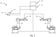
- Fig. 2 shows a schematic representation of a safety control system (10) according to the invention, wherein in this embodiment the display device (16) is formed by a signaling means (16), in particular a color-changing LED light ring (16) on the housing of the safety input means (14).
- a signaling means (16) in particular a color-changing LED light ring (16) on the housing of the safety input means (14).
- color-changing second signaling means in particular color-changing, luminous LED signal lights (24, 26), are attached to the automation system components (18, 20).
- Fig. 3 shows a schematic representation of a safety control system (10), wherein the second signaling means (24, 26) are passive light reflectors (24, 26), and a light projector (28) is provided at a suitable location in the automation system, which can irradiate the passive light reflectors (24, 26) with light.
- Fig. 4 shows the step-by-step sequence of the method according to the invention for all the above-mentioned embodiments.
- a first step (S1) the safety controller (12) determines a first automation system component (18) connected to it. This is done by exchanging data between the safety controller (12) and the individual automation system components (18) or with the automation system controller (22), which has knowledge of the status of the individual automation system components (18).
- the safety controller (12) can now visualize the effective range of the safety function by graphically displaying the automation system component (18) as an image or graphic model on the screen (16).
- the safety controller (12) visualizes the effective range of the safety function by simultaneously activating the LED light ring (16) on the housing of the safety input means (14) and the LED signal light (24) of the automation system component (18).
- the light reflector (24) of the automation system component (18) is illuminated by the light projector (28) in a color identical to the LED light ring (16).
- a further automation system component (20) is actively connected to the safety control (12) by the system operator or commissioning engineer or automatically by the automation system control (22)
- the safety control (12) updates the visualization of the current effective range on the screen (16) in such a way that the image of the further automation system component (20) is displayed in addition to the image of the existing automation system component (18). This symbolizes to the system operator that the safety function of the safety input means (14) now acts on the combination of automation system components (18, 20).
- the safety controller (12) updates the visualization of the current effective range by the LED signal light (26) of the automation system component (20) with the identical color of the LED light ring (16) on the housing of the safety input device (14) and the LED signal light (24) of the previous automation system component (18) is activated.
- the light reflector (26) with the identical color of the LED light ring (16) on the housing of the safety input device (14) and the light reflector (24) of the previous automation system component (18) is illuminated by the light projector (28).
- a third step (S3) which can be an alternative or supplementary to the previous second step, the automation system component (18, 20) is actively separated from the safety controller (12) by the system operator or commissioning engineer or automatically by the automation system controller (22), the safety controller (12) in the first embodiment updates the visualization of the current effective area on the screen (16) in such a way that the image of this automation system component (18, 20) is removed there. The system operator can thus see that the safety function of the safety input means (14) no longer affects the automation system component (18, 20).
- the safety controller (12) updates the visualization of the current effective range by switching off the LED light ring (16) and the LED signal light (24), or by switching off the illumination of the light reflector (24) by the light projector (28).
Landscapes
- Engineering & Computer Science (AREA)
- Physics & Mathematics (AREA)
- General Physics & Mathematics (AREA)
- Automation & Control Theory (AREA)
- Robotics (AREA)
- Mechanical Engineering (AREA)
- Human Computer Interaction (AREA)
- Manufacturing & Machinery (AREA)
- Safety Devices In Control Systems (AREA)
- Testing And Monitoring For Control Systems (AREA)
Description
- Die vorliegende Erfindung betrifft ein Sicherheitssteuerungssystem und ein Verfahren zum Ausführen einer Sicherheitsfunktion für zumindest eine Automationsanlagenkomponente, wobei das Sicherheitssteuerungssystem eine Sicherheitssteuerung und ein oder mehrere Sicherheitseingabemittel aufweist, und wobei an jedem Sicherheitseingabemittel eine Anzeigevorrichtung angeordnet ist und die Anzeigevorrichtung dazu eingerichtet ist einen Wirkbereich der Sicherheitsfunktion in Abhängigkeit von einer vorgegebenen Sicherheitskonfiguration der Sicherheitssteuerung zu visualisieren, wenn die Automationsanlagenkomponente mit der Sicherheitssteuerung verbunden ist.
- In industriellen Automationsanlagen ist es gemäß den geltenden Sicherheitsrichtlinien, z.B. der DIN EN ISO 10218-22012-06 gefordert, dass jede (Teil-)Komponente, die eine gefährdende Aktion durchführen kann, eine Sicherheitsfunktion, z.B. eine Not-Halt-Funktion aufweisen muss. Dafür werden bisher, ausgehend von den Normen, entsprechende Sicherheitstaster, in der Regel rote Not-Halt-Taster mit gelbem Gehäuse als Hintergrund verwendet. In einigen Ausführungen kann dieser Not-Halt-Taster bzw. sein Gehäuse auch aktiv beleuchtet sein, um diesen in schlechten Lichtverhältnissen innerhalb der Anlage besser sichtbar zu machen. Bei größeren Anlagen ist es bekannt für unterschiedliche Wirkbereiche einer Not-Halt-Funktion unterschiedliche Not-Halt-Taster zu verwenden, um eine entsprechende Not-Halt-Funktion nur für den betroffenen Wirkbereich zu aktivieren. Damit soll gewährleistet werden, dass bei Betätigung eines Not-Halt-Tasters nicht stets die gesamte Anlage in einen Not-Halt-Zustand versetzt wird. Zur Einhaltung der oben genannten Norm wurden dazu bisher die Not-Halt-Taster durch Beschriftungen oder Markierungen gekennzeichnet, um den Wirkbereich der ausgelösten Not-Halt-Funktion kenntlich zu machen.
- Dieses Vorgehen ist unproblematisch solange eine Automationsanlage bereits in Betrieb genommen wurde und im Betrieb unveränderlich ist, also eine feste Konfiguration aufweist. Bei der Inbetriebnahme selbst sind allerdings meist nur einige Teile der Automationsanlage funktionsfähig, während andere gerade im Aufbau befindlich und somit inaktiv sind. Durch Hinzunehmen von Anlagenkomponenten, wie z.B. einzelner Teile einer Arbeitszelle, wie Manipulatoren oder ähnliches ändert sich die Konfiguration der Anlage, ohne dabei aber automatisch Einfluss auf den Wirkbereich einer Sicherheitsfunktion zu nehmen. Dies stellt für den Inbetriebnehmer der Anlage ein erhöhtes Sicherheits- und Unfallrisiko dar.
- In ähnlicher Weise gilt dies, wenn eine ursprünglich bereits in Betrieb genommene Automationsanlage manuell oder automatisch umkonfiguriert werden muss, um z.B. auf sich ändernde Produktionsanforderungen Rücksicht zu nehmen. Beispielhaft wäre hier die Verwendung von flexibel einsetzbaren Robotersystemen, die modular in die bestehende Fertigungsanlage integriert, umkonfiguriert oder herausgenommen werden können. Dies gilt insbesondere im Falle der neuartig in der Produktion zum Einsatz kommenden kollaborierenden Roboter bzw. Cobots. Diese werden flexibel, je nach Anwendung, in den Fertigungsprozess integriert und unterliegen damit ebenfalls den im Prozess gültigen Sicherheitsnormen.
- Ebenso können koordinierte Roboterverbünde aus mehreren Robotern zur Laufzeit je nach Arbeitsschritt verändert werden. So z.B. können in einer Arbeitszelle drei Roboter R1, R2 und R3 vorhanden sein, wobei R2 abwechselnd mit R1 oder R3 koordiniert bewegt wird. Der Roboterverbund (R1 + R2) und der Roboterverbund (R2 + R3) stellen dabei zu unterschiedlichen Zeitpunkten unterschiedliche Wirkbereiche einer Sicherheitsfunktion einer Sicherheitssteuerung dar. Ein weiteres Beispiel für diese Roboterverbünde wäre der Stationswechsel einer mobilen Roboterplattform in einem matrixartigen Produktionskonzept. Hierbei operiert die mobile Roboterplattform meist autonom in der Fertigungsanlage und bildet zusammen mit einer Bearbeitungsstation, die selbst einen oder mehrere Bearbeitungsroboter aufweisen kann einen temporären Roboterverbund während des Bearbeitungsvorgangs in der Station.
- In allen genannten Fällen muss eine ständige Konformität der zu sichernden Anlage mit den geltenden Normen gewährleistet sein. Diese wird allerdings durch eine starre Beschriftung oder Markierung der Sicherheitseingabemittel nicht garantiert.
- Die
WO 2020/087098 A1 offenbart ein Verfahren zum Betreiben eines Maschinensteuerungssystems, wobei dazu ein mobiles, von einer Bedienperson tragbares Handbediengerät mit Nothalt-Betätigungselement vorgesehen ist. Die Maschinensteuerung und das Handbediengerät sind dazu eingerichtet, ein Abbild des Maschinensteuerungssystems sowie den oder die Wirkungsbereiche des zumindest einen Nothalt-Betätigungselements mittels eines Displays abzubilden. - Die
EP 3 418 825 A1 offenbart ein System mit Sicherheitssteuerung, die die Stromzufuhr zu einer Automationsanlage unterbrechen oder diese durch Eingabe eines Werkers in einen sicheren Zustand überführen kann. Das System beinhaltet ebenfalls einen durch den Werker bedienbaren Nothaltschalter sowie eine damit verbundene Benutzerschnittstelle. - Die
EP 2 098 926 A1 offenbart ein Verfahren zum Programmieren oder Konfigurieren einer Sicherheitssteuerung und einem Anschlussmodul, welches einen Eingang für einen Sensor bzw. einen Ausgang für einen Aktor aufweist, wobei über eine grafische Benutzeroberfläche Sensoren bzw. Aktoren ausgewählt und Eingängen bzw. Ausgängen des Anschlussmoduls zugeordnet werden. - Die
EP 1 716 982 A1 offenbart einen Industrieroboter mit Steuereinheit und einem Eingabemittel, wobei die Steuereinheit und das Eingabemittel zum Programmbetrieb des Industrieroboters kabellos kommunizieren können. Zur Kopplung der Steuereinheit und des Eingabemittels werden diese in unmittelbarer Nähe zueinander mittels einer temporäre Hilfsverbindung verbunden und gekoppelt. - Aufgabe der vorliegenden Erfindung ist es ein Sicherheitssteuerungssystem bereitzustellen und ein Verfahren anzugeben, um die Sicherheit des Anlagenbetreibers bzw. Inbetriebnehmers beim Auslösen einer Sicherheitsfunktion innerhalb einer Automationsanlage zu verbessern.
- Diese Aufgabe wird durch ein Sicherheitssteuerungssystem mit den Merkmalen des Anspruchs 1 und einem Verfahren mit den Merkmalen des Anspruchs 3 gelöst. Weitere Vorteile und Merkmale ergeben sich aus den Unteransprüchen.
- Die Aufgabe wird gelöst durch ein Sicherheitssteuerungssystem zum Ausführen einer Sicherheitsfunktion für zumindest eine Automationsanlagenkomponente, wobei das Sicherheitssteuerungssystem eine Sicherheitssteuerung und ein oder mehrere Sicherheitseingabemittel aufweist, und wobei das Ausführen der Sicherheitsfunktion durch Betätigung eines der Sicherheitseingabemittel ausgelöst wird. An jedem der Sicherheitseingabemittel ist dabei eine Anzeigevorrichtung angeordnet, die weiterhin dazu eingerichtet ist, den Wirkbereich der Sicherheitsfunktion in Abhängigkeit von einer vorgegebenen Sicherheitskonfiguration der Sicherheitssteuerung zu visualisieren, wenn die Automationsanlagenkomponente mit der Sicherheitssteuerung verbunden ist.
- Eine Sicherheitssteuerung im Sinne der Erfindung kann als eine eigenständige Einheit ausgestaltet sein oder als Teil einer Automatisierungssteuerung z.B. als Teilkomponente der Automationsanlage oder auch als übergeordnete Anlagensteuerung. Im Sinne der Erfindung weist die Sicherheitssteuerung bevorzugt eine Prozessoreinheit sowie Signaleingänge und Signalausgänge auf. Mittels dieser Signaleingänge und Signalausgänge, die vorzugsweise in sicherer Technik ausgeführt sein können, kommuniziert die Prozessoreinheit mit den Automatisierungsanlagenkomponenten und Sicherheitseingabemitteln, die mit der Sicherheitssteuerung verbunden sind.
- Als Automationsanlage wird eine Fertigungsanlage verstanden, wie sie aus der industriellen Praxis bekannt ist. Eine Automationsanlage kann aus einem oder mehreren, zumindest zum Teil automatisch arbeitenden Automationsanlagenkomponenten, z.B. Manipulatoren, insbesondere Industrierobotern, oder anderen Handhabungseinheiten, wie z.B. Fördereinrichtungen, Prozessstationen usw. bestehen. Miteinander kooperierende Automationsanlagenkomponenten können dabei zumindest temporär einen Verbund bilden, wobei der Verbund gemäß eines Anlagen- bzw. Applikationsprogramms eine gemeinsame Aufgabe durchführt.
- Ein Sicherheitseingabemittel kann ein, vorzugsweise in sicherer Technik ausgestalteter Sicherheitstaster, z.B. ein Not-Halt-Taster sein, der an einem sicheren Eingang der Sicherheitssteuerung angeschlossen ist. Bei Betätigung des Sicherheitseingabemittels wird ein sicherer Eingang der Sicherheitssteuerung geschalten und daraufhin durch die Sicherheitssteuerung eine Sicherheitsfunktion ausgelöst. In einer Automationsanlage können ein oder mehrere in der Anlage verteilte Sicherheitseingabemittel verwendet werden, die jeweils durch den Anlagenbetreiber betätigt werden können und jeweils einzeln die zugeordnete Sicherheitsfunktion auslösen. Das Verteilen mehrerer solcher Sicherheitseingabemittel innerhalb der Automationsanlage hat den Vorteil, dass die zu Grunde liegende Sicherheitsfunktion damit an mehreren Stellen ausgelöst werden kann. So muss der Anlagenbetreiber sich nicht erst zum Installationsort des einzigen Sicherheitseingabemittels zurückbegeben, um im Störfall reagieren zu können, sondern kann die Sicherheitsfunktion von einem beliebigen Ort in der Automationsanlage auslösen, sofern dort ein Sicherheitseingabemittel angebracht ist. Wichtig ist für den Inbetriebnehmer vor Ort zu erkennen, welche Automationsanlagenkomponente durch die Aktivierung des in dessen Reichweite befindlichen Sicherheitseingabemittels beeinflusst wird, mit anderen Worten, bis wohin sich also der Wirkbereich der Sicherheitsfunktion des Sicherheitseingabemittels erstreckt.
- Eine Sicherheitsfunktion im Sinne der Erfindung stellt eine vorgegebene Bewegungsreaktion der Automationsanlagenkomponente dar, die durch das Signal der Sicherheitssteuerung direkt, oder durch eine durch das Signal beeinflusste Bewegungssteuerung ausgelöst wird. Eine solche Bewegungsreaktion kann z.B. das vollständige Stillsetzen oder nur eine Bewegungsgeschwindigkeitsreduzierung der Automationsanlagenkomponente auf eine sichere Geschwindigkeit sein, um das Risiko einer Verletzung des Anlagenbetreibers zu minimieren.
- Die durch einen Not-Halt-Taster in der Regel ausgelöste Sicherheitsfunktion eines Manipulators, insbesondere eines Industrieroboters, ist die Not-Halt-Funktion. Bei dieser erfolgt als Bewegungsreaktion ein möglichst schnelles, vollständiges Stillsetzen der betroffenen Automationsanlagenkomponente. Der Not-Halt kann dabei beispielsweise mittels der Sicherheitssteuerung durch die unmittelbare Stromabschaltung zu den Antrieben und das gleichzeitige Einfallenlassen der mechanischen Bremsen der Automationsanlagenkomponente erzeugt werden, dem sogenannten "Stopp Kategorie 0". In einer weiteren Alternative kann die Not-Halt-Funktion das Stillsetzen des durch die Sicherheitsfunktion betroffenen Manipulators durch die Bewegungssteuerung mittels elektrischer und/oder mechanischer Bremsen nicht-bahntreu ("Stopp Kategorie 1") oder bahntreu erfolgen ("Stopp Kategorie 2").
- Der Wirkbereich der Sicherheitsfunktion ist im Sinne der Erfindung die zum Auslösezeitpunkt durch das Sicherheitseingabemittel von der Sicherheitsfunktion beeinflusste Automationsanlagenkomponente. Der Wirkbereich wird durch eine Sicherheitskonfiguration der Sicherheitssteuerung vorgegeben und kann sich während der Inbetriebnahme oder bei einer Umkonfiguration einer Automationsanlage oder während dessen Betrieb ändern.
- Die Sicherheitskonfiguration im Sinne der Erfindung ist eine durch den Anlagenbetreiber oder Inbetriebnehmer vorgegebene Gruppierung von Automationsanlagenkomponenten, die insbesondere zeitweise oder in Abhängigkeit von einem Programm- oder Applikationsablauf miteinander zusammenwirken. Die Sicherheitskonfiguration gibt damit an, welche Automationsanlagenkomponenten zu einem bestimmten Zeitpunkt im Programmablauf in einem Wirkbereich einer Sicherheitsfunktion liegen.
- Die Anzeigevorrichtung ist eine an dem Sicherheitseingabemittel angeordnete Einheit zur Visualisierung des aktuellen Wirkbereichs der Sicherheitsfunktion in Abhängigkeit einer vorgegebenen Sicherheitskonfiguration der Sicherheitssteuerung. Die Anzeigevorrichtung kann in einer Ausführungsform integrales Teilelement des Sicherheitseingabemittels oder in einer weiteren Ausführungsform in der unmittelbaren Nähe des Sicherheitseingabemittels angeordnet sein. Die Visualisierung kann entweder alleine durch die Anzeigevorrichtung erfolgen oder in Zusammenwirken mit weiteren Mitteln.
- In einer vorteilhaften Ausführung der vorliegenden Erfindung umfassen die Automationsanlagenkomponenten lokale Sicherheitssteuerungen, wobei die lokalen Sicherheitssteuerungen Teilelemente der Sicherheitssteuerung des Sicherheitssteuerungssystems darstellen können. Dies ist insbesondere dann bevorzugt, wenn die Automationsanlagenkomponenten zu einem bestimmten Zeitpunkt mit der Sicherheitssteuerung des Sicherheitssteuerungssystems verbunden vorliegen. In diesem Zusammenhang kann die vorgeschlagene Sicherheitssteuerung als zentrale Sicherheitssteuerung fungieren, wobei die zentrale Sicherheitssteuerung mit den lokalen Sicherheitssteuerungen der Automationsanlagenkomponenten verbunden vorliegt. Wird eine lokale Sicherheitssteuerung einer Automationsanlagenkomponente aus dem Netzwerk der zentralen und lokalen Sicherheitssteuerungen entfernt, so wirkt die entfernte lokale Sicherheitssteuerung nicht länger im Netzwerk der zentralen und verbleibenden lokalen Sicherheitssteuerungen. Die entfernte lokale Sicherheitssteuerung ist aber weiterhin in der Lage, die noch funktionsfähige Automationsanlagenkomponente, mit der sie verbunden ist, zu beeinflussen. Beispielsweise kann die entfernte lokale Sicherheitssteuerung die Automationsanlagenkomponente, für die sie zuständig ist, stillsetzen.
- Wenn eine Automationsanlagenkomponente eine lokale Sicherheitssteuerung aufweist, kann die lokale Sicherheitssteuerung ein Sicherheitseingabemittel umfassen, wobei dieses an der lokalen Sicherheitssteuerung vorhandene Sicherheitseingabemittel ein Sicherheitseingabemittel des vorgeschlagenen Sicherheitssteuerungssystems sein kann. Dies ist im Sinne der Erfindung insbesondere dann bevorzugt, wenn die entsprechende lokale Sicherheitssteuerung zu einem bestimmten Zeitpunkt mit der Sicherheitssteuerung des Sicherheitssteuerungssystems verbunden ist. Ein solches an der lokalen Sicherheitssteuerung vorgesehenes Sicherheitseingabemittel kann im Sinne der Erfindung bevorzugt auch als lokales Sicherheitseingabemittel bezeichnet werden.
- In einer nicht erfindungsgemäßen Ausführung kann die Anzeigevorrichtung als ein Bildschirm ausgebildet sein, der dazu eingerichtet ist den Wirkbereich der Sicherheitsfunktion, durch Anzeige einer graphischen Darstellung der mit der Sicherheitssteuerung verbundenen Automationsanlagenkomponente zu visualisieren. Der Bildschirm kann dabei bevorzugt als ein Touch-Display oder E-Ink Bildschirm ausgestaltet sein, auf dem sich die graphische Darstellung der Automationsanlagenkomponente visualisieren lässt. Die graphische Darstellung der mit der Sicherheitssteuerung verbundenen Automationsanlagenkomponente kann eine 2D- oder 3D-Repräsentation der Anlage z.B. eine skizzenhafte Zeichnung, ein CAD-Modell oder ein zuvor von der Automationsanlagenkomponente aufgenommenes Bild sein. Im Falle des Touch-Displays kann die Anzeige sogar interaktiv beeinflusst werden, z.B. je nach Bedarf die Größe der angezeigten Automationsanlagenkomponente verkleinert oder vergrößert werden oder gegebenenfalls auch Meldungen der Sicherheitssteuerung angezeigt bzw. durch den Anlagenbetreiber bestätigt werden.
- Die Anzeigevorrichtung in der vorliegende Erfindung ist ein farblich veränderbares erstes Signalmittel. Das Signalmittel kann ein leuchtaktives Leuchtmittel oder ein leuchtpassives Anzeigemittel sein. Das leuchtaktive Leuchtmittel kann weiter ein oder mehrere Glühlampen, Leuchtdioden oder Leuchtflächen umfassen. Die Verwendung von Leuchtdioden stellt eine kostengünstige und einfach an das Sicherheitseingabemittel bzw. in dessen Taster, Gehäuse oder Halterung anbringbare Möglichkeit der Visualisierung dar. Leuchtflächen bieten aufgrund ihrer größeren Strahlwirkung Vorteile gegenüber Leuchtdioden, da sie leichter erkannt werden können. Ein leuchtpassives Anzeigemittel kann eine farbveränderliche, insbesondere schaltbare Anzeige sein, deren Zustand sich in der visuellen Darstellung mindestens zweier Farben unterscheidet, beispielsweise ein E-Ink Bildschirm. Die farbliche Veränderbarkeit der Signalmittel bietet dem Anlagenbetreiber die Möglichkeit, das Sicherheitseingabemittel von einem farblich anders markierten Sicherheitseingabemittel einer weiteren Sicherheitssteuerung in einfacher Weise zu unterscheiden.
- Der Automationsanlagenkomponente sind ein oder mehrere farblich veränderbare zweite Signalmittel zugeordnet. Die zweiten Signalmittel können dabei wie die ersten Signalmittel leuchtaktive Leuchtmittel oder leuchtpassive Anzeigemittel sein. Die leuchtaktiven Leuchtmittel können weiter ein oder mehreren Glühlampen, Leuchtdioden oder Leuchtflächen umfassen. Im Sinne der Erfindung besonders bevorzugt ist die Verwendung von Leuchtmitteln, die bereits zu anderem Zwecke an Robotern vorgesehen sind, wie z.B. Leuchtringe an bzw. in der Roboterstruktur oder Signalleuchten an mobilen Roboterplattformen. Leuchtpassive Anzeigemittel können wieder farbveränderliche, insbesondere schaltbare Anzeigen sein, deren Zustand sich in der visuellen Darstellung mindestens zweier Farben unterscheidet, beispielsweise ein E-Ink Bildschirme. Weiter können leuchtpassive Anzeigemittel auch Lichtreflektoren, wie z.B. Spiegel oder Prismen sein. In analoger Weise, wie bei den ersten Signalmitteln, bietet die farbliche Veränderbarkeit der zweiten Signalmittel die Möglichkeit die Automationsanlagenkomponente von farblich anders markierten Automationsanlagenkomponenten zu unterscheiden. Die Verwendung von Lichtreflektoren ermöglicht es Projektoren an geeigneter Stelle in der Automationsanlage anzubringen, welche die Lichtreflektoren mit Licht der gewünschten Farbe anstrahlen. Dies bietet den Vorteil, dass keine zusätzlichen leuchtaktiven Leuchtmittel an den Automationsanlagenkomponenten angebracht werden müssen, sondern diese passiv beleuchtet werden können.
- Das erste und das ein oder mehrere zweite Signalmittel visualisieren den Wirkbereich der Sicherheitsfunktion dadurch, dass das erste Signalmittel und das ein oder mehrere zweite Signalmittel farblich übereinstimmen. Diese farbliche Übereinstimmung ermöglicht es einem Anlagenbetreiber besonders einfach eine Übereinstimmung zwischen dem zu verwendenden Sicherheitseingabemittel und der farblich identisch markiertem Automationsanlagenkomponente herzustellen, um im Notfall den richtigen Teil der Anlage durch eine Sicherheitsfunktion zu beeinflussen, z.B. vollständig stillzusetzen.
- Ein weiterer Aspekt der Erfindung betrifft ein Verfahren zum Ausführen einer Sicherheitsfunktion für zumindest eine Automationsanlagenkomponente mittels einer Sicherheitssteuerung und ein oder mehrere Sicherheitseingabemittel, wobei an dem Sicherheitseingabemittel eine Anzeigevorrichtung angeordnet ist. Das Verfahren weist die Schritte auf, wonach eine Sicherheitskonfiguration der Sicherheitssteuerung vorgegeben und diejenige Automationsanlagenkomponente ermittelt wird, die mit der Sicherheitssteuerung verbunden ist. Weiter weist das Verfahren den Schritt auf, dass der Wirkbereich der Sicherheitsfunktion in Abhängigkeit von der vorgegebenen Sicherheitskonfiguration auf der oder durch eine Anzeigevorrichtung des Sicherheitseingabemittels visualisiert wird. Das Ausführen der Sicherheitsfunktion wird durch Betätigung eines der Sicherheitseingabemittel ausgelöst.
- Die Vorgabe der Sicherheitskonfiguration der Sicherheitssteuerung kann durch den Anlagenbetreiber oder den Inbetriebnehmer erfolgen. Mittels der Sicherheitskonfiguration kann in der Sicherheitssteuerung hinterlegt werden, welche der Automationsanlagenkomponenten zu einem bestimmten Zeitpunkt im Programmablauf in einem Wirkbereich einer Sicherheitsfunktion liegen bzw. von dieser beeinflusst werden.
- Das Ermitteln der Automationsanlagenkomponente, die mit der Sicherheitssteuerung verbunden ist, kann entweder durch eine eigenständige Prozessoreinheit der Sicherheitssteuerung, eine Teileinheit einer Automatisierungssteuerung oder eine übergeordnete Anlagensteuerung erfolgen, wobei mittels einer Datenverbindung, insbesondere in sicherer Technik, mit den Teilen der Automationsanlage, insbesondere deren Komponenten deren Anwesenheit überprüft wird. Dazu können z.B. Datenpakete einmal oder wiederholt, vorzugsweise periodisch durch die Sicherheitssteuerung an die Automationsanlagenkomponente gesendet werden und bei erfolgter Antwort das Vorhandensein der antwortenden Automationsanlagenkomponente bestätigt werden. Abhängig vom Ergebnis des Schrittes des Ermittelns der mit der Sicherheitssteuerung verbundenen Automationsanlagenkomponente und in Abhängigkeit von der vorgegebenen Sicherheitskonfiguration der Sicherheitssteuerung wird dann im Schritt des Visualisierens der aktuelle, insbesondere sicherheitsrelevante Wirkbereich der Sicherheitsfunktion mittels der Anzeigevorrichtung visualisiert.
- In einer nicht erfindungsgemäßen Ausführung kann die Anzeigevorrichtung ein Bildschirm, insbesondere ein Touch-Display oder E-Ink Bildschirm sein. In dieser Ausführungsform erfolgt die Visualisierung des Wirkbereichs der Sicherheitsfunktion, durch Anzeige einer graphischen Darstellung, z.B. als ein Bild der mit der Sicherheitssteuerung verbundenen Automationsanlagenkomponente auf dem Bildschirm. Diese Darstellung ermöglich es dem Anlagenbetreiber beim ersten Blick auf den Bildschirm bereits den sicherheitsrelevanten Wirkbereich in der Automationsanlage zu erfassen.
- In einer Ausführung der vorliegenden Erfindung kann die Anzeigevorrichtung ein farblich veränderbares erstes Signalmittel sein. Das erste Signalmittel kann dabei ein leuchtaktives Leuchtmittel sein, das insbesondere ein oder mehrere Glühlampen, Leuchtdioden oder Leuchtflächen umfasst. In einer alternativen oder ergänzenden Ausführung kann das erste Signalmittel ein leuchtpassives Anzeigemittel sein, das eine farbveränderliche, insbesondere schaltbare Anzeige umfasst. Weiterhin können der Automationsanlagenkomponente ein oder mehrere farblich veränderbare zweite Signalmittel zugeordnet sein. Die zweiten Signalmittel können dabei leuchtaktive Leuchtmittel sein, die insbesondere ein oder mehrere Glühlampen, Leuchtdioden, Leuchtflächen umfassen. In einer alternativen oder ergänzenden Ausführung können die zweiten Signalmittel auch leuchtpassive Anzeigemittel sein, die farbveränderliche, insbesondere schaltbare Anzeigen umfassen, oder Lichtreflektoren, wie z.B. Spiegel oder Prismen sind. Weiter kann der Schritt des Visualisierens des Wirkbereichs der Sicherheitsfunktion durch eine farbliche Übereinstimmung des ersten und der zweiten Signalmittel erfolgen. Diese Visualisierung ist eine kostengünstige Möglichkeit dem Anlagenbetreiber durch eine rein visuelle Wahrnehmung die Automationsanlagenkomponenten zu identifizieren, welche aktuell durch die Sicherheitsfunktion des Sicherheitseingabemittels beeinflusst werden.
- In einer weiteren vorteilhaften Ausführung der vorliegenden Erfindung kann bei dem Verfahren die Visualisierung durch die Anzeigevorrichtung in Abhängigkeit von der vorgegebenen Sicherheitskonfiguration der Sicherheitssteuerung aktualisiert werden, wenn die Automationsanlagenkomponente mit der Sicherheitssteuerung verbunden oder von der Sicherheitssteuerung getrennt wird. Die Sicherheitssteuerung kann in einer besonders bevorzugten Ausführungsform der Erfindung die Aktivierung bzw. Deaktivierung ihrer Signaleingänge und Signalausgänge überwachen und ein Signal zur Aktualisierung der Anzeigevorrichtung erzeugen, insbesondere wenn die Datenverbindung zu einzelnen Automationsanlagenkomponenten aufgebaut wird oder wenn diese abbricht.
- Die Aktivierung bzw. Deaktivierung kann aktiv durch physisches Verbinden der einzelnen Komponenten der Automationsanlage mit der Sicherheitssteuerung erfolgen. So kann dabei eine kabelgebundene oder auch drahtlose Kommunikation zwischen der Komponente und der Sicherheitssteuerung etabliert werden. In einer anderen, ergänzenden Alternative kann diese Verbindung bereits bestehen und im Ablaufprogramm der Automationsanlage wird automatisch, zeit- oder prozessabhängig eine Aktivierung bzw. Deaktivierung der Datenverbindung vorgenommen. Dies kann durch das digitale Schalten eines Signalein- bzw. Signalausgangs in der Automationsanlagenkomponente oder einer zwischen der Automationsanlagenkomponente und der Sicherheitssteuerung zwischengeschalteten Programmablaufsteuerung oder Anlagensteuerung stattfinden.
- Bei Herstellen oder Trennen der Verbindung ändert dann die Sicherheitssteuerung in Abhängigkeit von der vorgegebenen Sicherheitskonfiguration der Sicherheitssteuerung den Zustand der Anzeigevorrichtung. Im Beispiel des Bildschirms kann sich die graphische Darstellung, also das angezeigte Bild derart ändern, dass dadurch der Wirkbereich der Sicherheitsfunktion präzise dargestellt wird. Wenn nun eine neue Automationsanlagenkomponente zur bestehenden Automationsanlagenkomponente hinzugefügt wird und diese gemäß der vorgegebenen Sicherheitskonfiguration Teil des Wirkbereichs ist, wird ein neues Bild auf dem Bildschirm dargestellt, das neben der bereits angezeigten Automationsanlagenkomponente die neue Automationsanlagenkomponente zeigt. Am Beispiel der Signalmittel kann die Sicherheitssteuerung mit gleichem Ziel, den Wirkbereich der Sicherheitsfunktion präzise darzustellen, die Farbe des Signalmittels an der neuen Automationsanlagenkomponente derart einstellen, dass diese nun mit der Farbe des Signalmittels an dem Sicherheitseingabemittel übereinstimmt, um die Zugehörigkeit zum Wirkbereich der Sicherheitsfunktion zu visualisieren.
- Zeigt die Anzeigevorrichtung des Sicherheitseingabemittels beispielsweise aktuell kein Bild an, bzw. leuchten die Leuchtmittel des Sicherheitseingabemittels nicht, signalisiert es dem Anlagenbetreiber weiter, dass dieses Sicherheitseingabemittel gerade keine Sicherheitsfunktion hat. Bei einem farblich markierten Sicherheitseingabemittel, zu dem keine farbliche Übereinstimmung mit den Signalmitteln einer vorhandenen Automationsanlagenkomponente besteht, wird dem Anlagenbetreiber damit signalisiert, dass dieses Sicherheitseingabemittel keine geeignete Sicherheitsfunktion bzgl. der vorhandenen Automationsanlagenkomponente auslösen kann. Gleiches gilt wenn der Bildschirm des Sicherheitseingabemittels ein anderes Bild als das von der vorhandenen Automationsanlagenkomponente anzeigt. Nur wenn eine farbliche Übereinstimmung der Signalmittel des Sicherheitseingabemittels und der Signalmittel in den betroffenen Automationsanlagenkomponenten besteht, bzw. nur wenn die Automationsanlagenkomponenten, die der Anlagenbetreiber beeinflussen möchte auf dem Bildschirm des Sicherheitseingabemittels angezeigt werden, dann kann der Anlagenbetreiber in sicherer Weise die Anlage beeinflussen, z.B. stillsetzen.
- Weitere Vorteile, Merkmale und Einzelheiten der Erfindung ergeben sich aus den nachfolgenden Ausführungsbeispielen und den Figuren.
- Hierzu zeigt, teilweise schematisiert:
- Fig. 1:
- Sicherheitssteuerungssystem mit Bildschirm;
- Fig. 2:
- Sicherheitssteuerungssystem mit aktiven zweiten Signalmitteln;
- Fig. 3:
- Sicherheitssteuerungssystem mit passiven zweiten Signalmitteln;
- Fig. 4:
- Darstellung der Verfahrensschritte;
-
Fig. 1 zeigt eine schematische Darstellung eines nicht erfindungsgemäßen Sicherheitssteuerungssystems (10). Das Sicherheitssteuerungssystem (10) umfasst dabei eine Sicherheitssteuerung (12), ein Sicherheitseingabemittel (14), das als Sicherheitstaster ausgebildet sein kann, sowie eine Anzeigevorrichtung (16), die als ein Bildschirm ausgebildet sein kann. - Der Bildschirm (16) ist dabei für den Anlagenbetreiber gut sichtbar, insbesondere an der Oberseite im Gehäuse des Sicherheitstasters (14) integriert. In einer weiteren, nicht dargestellten Variante dieser Ausführungsform sind der Sicherheitstaster (14) und der Bildschirm (16) integrale Bestandteile eines Eingabegerätes der Automationsanlage. Mittels eines solchen Eingabegeräts werden in der Regel während der Inbetriebnahme ein oder mehrere Automationsanlagenkomponenten (18, 20) kommandiert, um ein Anlagenprogramm zu erstellen. Während des automatischen Betriebs einer Automationsanlagenkomponente (18, 20) dient der Bildschirm (16) dieses Automationsanlageneingabegerätes als Statusanzeige des aktuellen Programmablaufs.
- Die Sicherheitssteuerung (12) kann insbesondere Bestandteil einer Automationsanlagensteuerung (22) sein, durch welche zumindest teilweise die Steuerung der Automationsanlage erfolgt. In der Sicherheitssteuerung (12) wird durch den Anlagenbetreiber bzw. Inbetriebnehmer hinterlegt, welche der Automationsanlagenkomponenten zu einem bestimmten Zeitpunkt im Programmablauf in einem Wirkbereich einer Sicherheitsfunktion liegen bzw. von dieser beeinflusst werden. Ergänzend oder alternativ dazu kann die Sicherheitssteuerung (12) als zentrale Sicherheitssteuerung fungieren und mit den einzelnen lokalen Sicherheitssteuerungen der einzelnen Automationsanlagenkomponente (18, 20) zusammenwirken, wenn die entsprechende Automationsanlagenkomponente (18, 20) mit einer zentralen Sicherheitssteuerung (12) verbunden ist. Dabei wird die Konfiguration der lokalen Sicherheitssteuerung in die Sicherheitskonfiguration der zentralen Sicherheitssteuerung (12) integriert oder durch diese berücksichtigt.
- Die Automationsanlagenkomponenten (18, 20) können insbesondere Manipulatoren, besonders bevorzugt Roboter, sein, die entweder alleine oder zumindest temporär in einem Verbund miteinander kooperieren können. Ein solcher Manipulatorverbund wird hier am Beispiel dreier miteinander kooperierender Roboter R1, R2 und R3 dargestellt. Roboter R2 kooperiert dabei abwechselnd mit R1 oder R3 und wird mit diesen koordiniert bewegt, um eine entsprechende automatisierte Aufgabe auszuführen, z.B. das abwechselnde Bearbeiten eines durch den Roboter R2 gehaltenen Bauteils. Sobald Roboter R2 innerhalb eines Applikationsschrittes mit dem Roboter R1 zusammen die Bearbeitung des Bauteils unternimmt, bilden diese den Roboterverbund (R1 + R2). Während dieser Zeit kann der Wirkbereich einer Sicherheitsfunktion der Sicherheitssteuerung (12) den Roboterverbund (R1 + R2) umfassen. In einem nächsten Applikationsschritt kooperiert der Roboter R2 beispielsweise zur weiteren Bearbeitung des Bauteils mit dem Roboter R3. In diesem Applikationsschritt kann der Wirkbereich einer Sicherheitsfunktion der Sicherheitssteuerung (12) den Roboterverbund (R2 + R3) umfassen.
-
Fig. 2 zeigt in einer schematischen Darstellung ein erfindungsgemäßes Sicherheitssteuerungssystem (10), wobei in dieser Ausführungsform die Anzeigevorrichtung (16) von einem Signalmittel (16), insbesondere einem farbveränderlichen LED-Leuchtring (16) am Gehäuse des Sicherheitseingabemittels (14) gebildet wird. - Im Weiteren sind in dieser Ausführungsform an den Automationsanlagenkomponenten (18, 20) jeweils weitere farbveränderliche zweite Signalmittel (24, 26), insbesondere farbveränderliche, leuchtaktive LED-Signalleuchten (24, 26) angebracht.
-
Fig. 3 zeigt in einer schematischen Darstellung ein Sicherheitssteuerungssystem (10), wobei die zweiten Signalmittel (24, 26) passive Lichtreflektoren (24, 26) sind, und an geeigneter Stelle in der Automationsanlage ein Lichtprojektor (28) vorgesehen ist, der die passive Lichtreflektoren (24, 26) mit Licht bestrahlen kann. -
Fig. 4 zeigt den schrittweisen Ablauf des erfindungsgemäßen Verfahrens zu allen oben genannten Ausführungsformen. - In einem ersten Schritt (S1) ermittelt die Sicherheitssteuerung (12) eine erste mit ihr verbundene Automationsanlagenkomponente (18). Dies geschieht durch den Datenaustausch der Sicherheitssteuerung (12) mit den einzelnen Automationsanlagenkomponenten (18) oder mit der Automationsanlagensteuerung (22), die Kenntnis über den Status der einzelnen Automationsanlagenkomponenten (18) hat.
- Basierend auf dem Ergebnis dieser Ermittlung und in Abhängigkeit von der vorgegebenen Sicherheitskonfiguration der Sicherheitssteuerung (12) kann die Sicherheitssteuerung (12) nun den Wirkbereich der Sicherheitsfunktion durch die graphische Darstellung der Automationsanlagenkomponente (18) als Bild oder graphisches Modell auf dem Bildschirm (16) visualisieren.
- Gemäß dem Ausführungsbeispiel der Erfindung visualisiert die Sicherheitssteuerung (12) den Wirkbereich der Sicherheitsfunktion durch die gleichzeitige Aktivierung des LED-Leuchtrings (16) am Gehäuse des Sicherheitseingabemittels (14) und der LED-Signalleuchte (24) der Automationsanlagenkomponente (18). Gemäß dem dritten Ausführungsbeispiel der Erfindung erfolgt gleichzeitig zur Aktivierung des LED-Leuchtrings (16) am Gehäuse des Sicherheitseingabemittels (14) die Beleuchtung des Lichtreflektors (24) der Automationsanlagenkomponente (18) durch den Lichtprojektor (28) in einer zum LED-Leuchtring (16) identischen Farbe.
- Wird in einem zweiten Schritt (S2) eine weitere Automationsanlagenkomponente (20) aktiv durch den Anlagenbetreiber oder Inbetriebnehmer oder automatisch durch die Automationsanlagensteuerung (22) mit der Sicherheitssteuerung (12) verbunden, so aktualisiert die Sicherheitssteuerung (12) die Visualisierung des aktuellen Wirkbereichs auf dem Bildschirm (16) derart, dass zusätzlich zum Bild der bestehenden Automationsanlagenkomponente (18) das Bild der weiteren Automationsanlagenkomponente (20) angezeigt wird. Somit wird dem Anlagenbetreiber symbolisiert, dass die Sicherheitsfunktion des Sicherheitseingabemittels (14) nun auf den Verbund der Automationsanlagenkomponenten (18, 20) wirkt.
- Gemäß dem Ausführungsbeispiel der Erfindung aktualisiert die Sicherheitssteuerung (12) die Visualisierung des aktuellen Wirkbereichs dadurch, dass die LED-Signalleuchte (26) der Automationsanlagenkomponente (20) mit der identischen Farbe des LED-Leuchtrings (16) am Gehäuse des Sicherheitseingabemittels (14) und der LED-Signalleuchte (24) der bisherigen Automationsanlagenkomponente (18) aktiviert wird. Der Lichtreflektor (26) mit der identischen Farbe des LED-Leuchtrings (16) am Gehäuse des Sicherheitseingabemittels (14) und des Lichtreflektors (24) der bisherigen Automationsanlagenkomponente (18) wird durch den Lichtprojektors (28) beleuchtet.
- Wird in einem dritten Schritt (S3), der zum vorherigen zweiten Schritt alternativ oder ergänzend sein kann, die Automationsanlagenkomponente (18, 20) aktiv durch den Anlagenbetreiber oder Inbetriebnehmer oder automatisch durch die Automationsanlagensteuerung (22), von der Sicherheitssteuerung (12) getrennt, so aktualisiert die Sicherheitssteuerung (12) in dem ersten Ausführungsbeispiel die Visualisierung des aktuellen Wirkbereichs auf dem Bildschirm (16) derart, dass dort das Bild dieser Automationsanlagenkomponente (18, 20) entfernt wird. Somit wird dem Anlagenbetreiber ersichtlich, dass die Sicherheitsfunktion des Sicherheitseingabemittels (14) nicht mehr auf die Automationsanlagenkomponente (18, 20) wirkt.
- Die Sicherheitssteuerung (12) aktualisiert die Visualisierung des aktuellen Wirkbereichs durch Abschalten des LED-Leuchtrings (16) und der LED-Signalleuchte (24), bzw. durch Abschalten der Beleuchtung des Lichtreflektors (24) durch den Lichtprojektor (28).
-
- 10
- Sicherheitssteuerungssystem
- 12
- Sicherheitssteuerung
- 14
- Sicherheitseingabemittel
- 16
- Anzeigevorrichtung
- 18, 20
- Automationsanlagenkomponenten
- 22
- Automationsanlagensteuerung
- 24, 26
- zweite Signalmittel
- 28
- Lichtprojektor
- S1
- erster Verfahrensschritt
- S2
- zweiter Verfahrensschritt
- S3
- dritter Verfahrensschritt
Claims (4)
- Sicherheitssteuerungssystem (10) zum Ausführen einer Sicherheitsfunktion für zumindest eine Automationsanlagenkomponente (18,20), wobei das Sicherheitssteuerungssystem (10) eine Sicherheitssteuerung (12) und ein oder mehrere Sicherheitseingabemittel (14) aufweist, und wobei das Ausführen der Sicherheitsfunktion durch Betätigung eines der Sicherheitseingabemittel (14) ausgelöst wird wobei an jedem Sicherheitseingabemittel (14) eine Anzeigevorrichtung (16) angeordnet ist, wobei die Anzeigevorrichtung (16) dazu eingerichtet ist einen Wirkbereich der Sicherheitsfunktion in Abhängigkeit von einer vorgegebenen Sicherheitskonfiguration der Sicherheitssteuerung (12) zu visualisieren, wenn die Automationsanlagenkomponente (18,20) mit der Sicherheitssteuerung (12) verbunden ist wobei die Anzeigevorrichtung (16) ein farblich veränderbares erstes Signalmittel ist und dadurch gekennzeichnet, dass der Automationsanlagenkomponente (18,20) ein oder mehrere farblich veränderbare zweite Signalmittel (24,26) zugeordnet sind und dass das erste und das ein oder mehrere zweite Signalmittel (24,26) den Wirkbereich der Sicherheitsfunktion dadurch visualisieren, dass das erste Signalmittel und das ein oder mehrere zweite Signalmittel farblich übereinstimmen.
- Sicherheitssteuerungssystem (10) nach Anspruch 1,
dadurch gekennzeichnet, dass die Sicherheitssteuerung (12) als zentrale Sicherheitssteuerung fungiert und die Automationsanlagenkomponente eine lokale Sicherheitssteuerung umfasst, wobei die zentrale Sicherheitssteuerung mit der lokalen Sicherheitssteuerung der Automationsanlagenkomponenten verbunden ist. - Verfahren zum Ausführen einer Sicherheitsfunktion für zumindest eine Automati onsanlagenkomponente (18,20) mittels einer Sicherheitssteuerung (12) und ein oder mehrere Sicherheitseingabemittel (14), wobei das Ausführen der Sicherheitsfunktion durch Betätigung eines der Sicherheitseingabemittel (14) ausgelöst wird, und an dem Sicherheitseingabemittel (14) eine Anzeigevorrichtung (16) angeordnet ist, aufweisend die Schritte- Vorgeben einer Sicherheitskonfiguration für die Sicherheitssteuerung (12)- Ermitteln der Automationsanlagenkomponente (18,20), die mit der Sicherheitssteuerung (12) verbunden ist;- Visualisieren des Wirkbereichs der Sicherheitsfunktion auf der oder durch die Anzeigevorrichtung (16) in Abhängigkeit von der vorgegebenen Sicherheitskonfiguration wobei die Anzeigevorrichtung (16) ein farblich veränderbares erstes Signalmittel ist, dadurch gekennzeichnet dass der Automationsanlagenkomponente (18,20) ein oder mehrere farblich veränderbare zweite Signalmittel (24,26) zugeordnet sind, und dass das Visualisieren des Wirkbereichs der Sicherheitsfunktion durch eine farbliche Übereinstimmung des ersten und der zweiten Signalmittel erfolgt.
- Verfahren zum Ausführen einer Sicherheitsfunktion nach Anspruch 3 weiter gekennzeichnet durch die Schritte- Aktualisieren der Visualisierung durch die Anzeigevorrichtung (16) in Abhängigkeit von der vorgegebenen Sicherheitskonfiguration, wenn die Automationsanlagenkomponente (18,20) mit der Sicherheitssteuerung (12) verbunden oder von der Sicherheitssteuerung (12) getrennt wird.
Applications Claiming Priority (2)
| Application Number | Priority Date | Filing Date | Title |
|---|---|---|---|
| DE102020115104.7A DE102020115104A1 (de) | 2020-06-08 | 2020-06-08 | Sicherheitssteuerungssystem und Verfahren zum Ausführen einer Sicherheitsfunktion |
| PCT/EP2021/063824 WO2021249757A1 (de) | 2020-06-08 | 2021-05-25 | Sicherheitssteuerungssystem und verfahren zum ausführen einer sicherheitsfunktion |
Publications (2)
| Publication Number | Publication Date |
|---|---|
| EP4162330A1 EP4162330A1 (de) | 2023-04-12 |
| EP4162330B1 true EP4162330B1 (de) | 2025-01-01 |
Family
ID=76181128
Family Applications (1)
| Application Number | Title | Priority Date | Filing Date |
|---|---|---|---|
| EP21728532.9A Active EP4162330B1 (de) | 2020-06-08 | 2021-05-25 | Sicherheitssteuerungssystem und verfahren zum ausführen einer sicherheitsfunktion |
Country Status (3)
| Country | Link |
|---|---|
| EP (1) | EP4162330B1 (de) |
| DE (1) | DE102020115104A1 (de) |
| WO (1) | WO2021249757A1 (de) |
Families Citing this family (2)
| Publication number | Priority date | Publication date | Assignee | Title |
|---|---|---|---|---|
| DE102022111226B3 (de) | 2022-05-05 | 2023-07-27 | Franka Emika Gmbh | Gekapselte Sicherheit für den Betrieb eines Robotermanipulators |
| DE102022112439B3 (de) | 2022-05-05 | 2023-07-27 | Franka Emika Gmbh | Sicherer Roboter |
Family Cites Families (6)
| Publication number | Priority date | Publication date | Assignee | Title |
|---|---|---|---|---|
| DE602005006531D1 (de) * | 2005-04-19 | 2008-06-19 | Comau Spa | Verfahren zur Steuerung von industriellen Robotern und entsprechend gesteuerte Roboter, Robotersysteme und Computerprogramme |
| ATE509305T1 (de) * | 2008-03-07 | 2011-05-15 | Sick Ag | Verfahren und vorrichtung zum programmieren und/oder konfigurieren einer sicherheitssteuerung |
| DE102010017857B4 (de) | 2010-04-22 | 2019-08-08 | Sick Ag | 3D-Sicherheitsvorrichtung und Verfahren zur Absicherung und Bedienung mindestens einer Maschine |
| US10338557B2 (en) * | 2017-06-19 | 2019-07-02 | Rockwell Automation Technologies, Inc. | Systems and methods for safety input devices |
| AT521872A1 (de) | 2018-10-31 | 2020-05-15 | Keba Ag | Verfahren zum Betreiben eines Maschinensteuerungssystems sowie entsprechendes Maschinensteuerungssystem |
| AT521871B1 (de) | 2018-10-31 | 2021-10-15 | Keba Ag | Verfahren zum Betreiben eines Maschinensteuerungssystems sowie Maschinensteuerungssystem |
-
2020
- 2020-06-08 DE DE102020115104.7A patent/DE102020115104A1/de active Pending
-
2021
- 2021-05-25 EP EP21728532.9A patent/EP4162330B1/de active Active
- 2021-05-25 WO PCT/EP2021/063824 patent/WO2021249757A1/de not_active Ceased
Also Published As
| Publication number | Publication date |
|---|---|
| EP4162330A1 (de) | 2023-04-12 |
| DE102020115104A1 (de) | 2021-12-09 |
| WO2021249757A1 (de) | 2021-12-16 |
Similar Documents
| Publication | Publication Date | Title |
|---|---|---|
| DE10110776B4 (de) | Verfahren zur Zuordnung einer mobilen Bedien- und/oder Beobachtungseinrichtung zu einer Maschine sowie Bedien- und/oder Beobachtungseinrichtung hierfür | |
| EP2317410B1 (de) | Sicherheitssteuerung | |
| EP3961318B1 (de) | Verfahren zur konfiguration einer modularen sicherheitsschaltvorrichtung | |
| EP1890210A1 (de) | Verfahren und Vorrichtung zur Kennzeichnung des Betriebszustands eines Bedienelementes | |
| EP2678745B1 (de) | Verfahren zur einrichtung einer fördervorrichtung | |
| EP3451087B1 (de) | System und verfahren zur auswahl und identifikation von feldgeräten | |
| EP4162330B1 (de) | Sicherheitssteuerungssystem und verfahren zum ausführen einer sicherheitsfunktion | |
| EP3873702B1 (de) | Verfahren zum betreiben eines maschinensteuerungssystems sowie maschinensteuerungssystem | |
| EP3889981B1 (de) | Steuerungssystem für elektrisch gesteuerte anlagen | |
| EP2098926A1 (de) | Verfahren und Vorrichtung zum Programmieren und/oder Konfigurieren einer Sicherheitssteuerung | |
| EP2367083A1 (de) | Vorrichtung zur Erstellung eines Programms für eine speicherprogrammierbare Steuerung, Programmiereinrichtung und Verfahren zur Programmierung einer speicherprogrammierbaren Steuerung | |
| EP3192091A1 (de) | Überwachter adaptierbarer notausschalter | |
| WO2020087099A1 (de) | Verfahren zum betreiben eines maschinensteuerungssystems sowie entsprechendes maschinensteuerungssystem | |
| EP3969970A1 (de) | Verfahren zur darstellung und bedienung von produktionsmitteln, insbesondere für die kunststoffverarbeitende industrie | |
| WO2005036492A1 (de) | Hmi system mit einem mobilen bedien- und beobachtungsgerät für sicherheitsrelevante bedienungen an einer technischen anlage | |
| AT518665B1 (de) | Steuerungssystem für elektrisch gesteuerte Anlagen | |
| EP0623878A2 (de) | Anzeigeeinrichtung für ein Installationsbussystem | |
| LU503513B1 (de) | Bedieneinheit und Verfahren zum Bedienen einer Anlage mit einer Bedieneinheit | |
| DE19940874B4 (de) | Verfahren zum Konfigurieren eines sicheren Busteilnehmers und sicheres Steuerungssystem mit einem solchen | |
| WO2023110490A1 (de) | Verfahren zum zuordnen einer not-halt-funktionalität und automatisierungsanlage | |
| EP2490086B1 (de) | Verfahren zum Betrieb eines Automatisierungssystems und nach dem Verfahren arbeitendes Computerprogramm | |
| EP3660597B1 (de) | Schaltgerät zum fehlersicheren ein- oder ausschalten einer gefährlichen maschinenanlage | |
| AT521873B1 (de) | Industrielles Steuerungssystem | |
| DE202024105124U1 (de) | System mit elektronischen Bauteilen | |
| DE202013103586U1 (de) | Vorrichtung zum Konfigurieren und/oder Programmieren einer Sicherheitssteuerung |
Legal Events
| Date | Code | Title | Description |
|---|---|---|---|
| STAA | Information on the status of an ep patent application or granted ep patent |
Free format text: STATUS: UNKNOWN |
|
| STAA | Information on the status of an ep patent application or granted ep patent |
Free format text: STATUS: THE INTERNATIONAL PUBLICATION HAS BEEN MADE |
|
| PUAI | Public reference made under article 153(3) epc to a published international application that has entered the european phase |
Free format text: ORIGINAL CODE: 0009012 |
|
| STAA | Information on the status of an ep patent application or granted ep patent |
Free format text: STATUS: REQUEST FOR EXAMINATION WAS MADE |
|
| 17P | Request for examination filed |
Effective date: 20221222 |
|
| AK | Designated contracting states |
Kind code of ref document: A1 Designated state(s): AL AT BE BG CH CY CZ DE DK EE ES FI FR GB GR HR HU IE IS IT LI LT LU LV MC MK MT NL NO PL PT RO RS SE SI SK SM TR |
|
| P01 | Opt-out of the competence of the unified patent court (upc) registered |
Effective date: 20230528 |
|
| DAV | Request for validation of the european patent (deleted) | ||
| DAX | Request for extension of the european patent (deleted) | ||
| GRAP | Despatch of communication of intention to grant a patent |
Free format text: ORIGINAL CODE: EPIDOSNIGR1 |
|
| STAA | Information on the status of an ep patent application or granted ep patent |
Free format text: STATUS: GRANT OF PATENT IS INTENDED |
|
| INTG | Intention to grant announced |
Effective date: 20240814 |
|
| GRAS | Grant fee paid |
Free format text: ORIGINAL CODE: EPIDOSNIGR3 |
|
| GRAA | (expected) grant |
Free format text: ORIGINAL CODE: 0009210 |
|
| STAA | Information on the status of an ep patent application or granted ep patent |
Free format text: STATUS: THE PATENT HAS BEEN GRANTED |
|
| AK | Designated contracting states |
Kind code of ref document: B1 Designated state(s): AL AT BE BG CH CY CZ DE DK EE ES FI FR GB GR HR HU IE IS IT LI LT LU LV MC MK MT NL NO PL PT RO RS SE SI SK SM TR |
|
| REG | Reference to a national code |
Ref country code: GB Ref legal event code: FG4D Free format text: NOT ENGLISH |
|
| REG | Reference to a national code |
Ref country code: CH Ref legal event code: EP |
|
| REG | Reference to a national code |
Ref country code: DE Ref legal event code: R096 Ref document number: 502021006279 Country of ref document: DE |
|
| REG | Reference to a national code |
Ref country code: IE Ref legal event code: FG4D Free format text: LANGUAGE OF EP DOCUMENT: GERMAN |
|
| REG | Reference to a national code |
Ref country code: LT Ref legal event code: MG9D |
|
| REG | Reference to a national code |
Ref country code: NL Ref legal event code: MP Effective date: 20250101 |
|
| PG25 | Lapsed in a contracting state [announced via postgrant information from national office to epo] |
Ref country code: NL Free format text: LAPSE BECAUSE OF FAILURE TO SUBMIT A TRANSLATION OF THE DESCRIPTION OR TO PAY THE FEE WITHIN THE PRESCRIBED TIME-LIMIT Effective date: 20250101 |
|
| PG25 | Lapsed in a contracting state [announced via postgrant information from national office to epo] |
Ref country code: FI Free format text: LAPSE BECAUSE OF FAILURE TO SUBMIT A TRANSLATION OF THE DESCRIPTION OR TO PAY THE FEE WITHIN THE PRESCRIBED TIME-LIMIT Effective date: 20250101 |
|
| PG25 | Lapsed in a contracting state [announced via postgrant information from national office to epo] |
Ref country code: PL Free format text: LAPSE BECAUSE OF FAILURE TO SUBMIT A TRANSLATION OF THE DESCRIPTION OR TO PAY THE FEE WITHIN THE PRESCRIBED TIME-LIMIT Effective date: 20250101 |
|
| PGFP | Annual fee paid to national office [announced via postgrant information from national office to epo] |
Ref country code: DE Payment date: 20250402 Year of fee payment: 5 |
|
| PG25 | Lapsed in a contracting state [announced via postgrant information from national office to epo] |
Ref country code: ES Free format text: LAPSE BECAUSE OF FAILURE TO SUBMIT A TRANSLATION OF THE DESCRIPTION OR TO PAY THE FEE WITHIN THE PRESCRIBED TIME-LIMIT Effective date: 20250101 |
|
| PG25 | Lapsed in a contracting state [announced via postgrant information from national office to epo] |
Ref country code: IS Free format text: LAPSE BECAUSE OF FAILURE TO SUBMIT A TRANSLATION OF THE DESCRIPTION OR TO PAY THE FEE WITHIN THE PRESCRIBED TIME-LIMIT Effective date: 20250501 Ref country code: NO Free format text: LAPSE BECAUSE OF FAILURE TO SUBMIT A TRANSLATION OF THE DESCRIPTION OR TO PAY THE FEE WITHIN THE PRESCRIBED TIME-LIMIT Effective date: 20250401 |
|
| PG25 | Lapsed in a contracting state [announced via postgrant information from national office to epo] |
Ref country code: HR Free format text: LAPSE BECAUSE OF FAILURE TO SUBMIT A TRANSLATION OF THE DESCRIPTION OR TO PAY THE FEE WITHIN THE PRESCRIBED TIME-LIMIT Effective date: 20250101 |
|
| PG25 | Lapsed in a contracting state [announced via postgrant information from national office to epo] |
Ref country code: PT Free format text: LAPSE BECAUSE OF FAILURE TO SUBMIT A TRANSLATION OF THE DESCRIPTION OR TO PAY THE FEE WITHIN THE PRESCRIBED TIME-LIMIT Effective date: 20250502 Ref country code: LV Free format text: LAPSE BECAUSE OF FAILURE TO SUBMIT A TRANSLATION OF THE DESCRIPTION OR TO PAY THE FEE WITHIN THE PRESCRIBED TIME-LIMIT Effective date: 20250101 |
|
| PGFP | Annual fee paid to national office [announced via postgrant information from national office to epo] |
Ref country code: FR Payment date: 20250401 Year of fee payment: 5 |
|
| PG25 | Lapsed in a contracting state [announced via postgrant information from national office to epo] |
Ref country code: BG Free format text: LAPSE BECAUSE OF FAILURE TO SUBMIT A TRANSLATION OF THE DESCRIPTION OR TO PAY THE FEE WITHIN THE PRESCRIBED TIME-LIMIT Effective date: 20250101 Ref country code: GR Free format text: LAPSE BECAUSE OF FAILURE TO SUBMIT A TRANSLATION OF THE DESCRIPTION OR TO PAY THE FEE WITHIN THE PRESCRIBED TIME-LIMIT Effective date: 20250402 |
|
| PGFP | Annual fee paid to national office [announced via postgrant information from national office to epo] |
Ref country code: CH Payment date: 20250601 Year of fee payment: 5 |
|
| PGFP | Annual fee paid to national office [announced via postgrant information from national office to epo] |
Ref country code: AT Payment date: 20250721 Year of fee payment: 5 |
|
| PG25 | Lapsed in a contracting state [announced via postgrant information from national office to epo] |
Ref country code: CZ Free format text: LAPSE BECAUSE OF FAILURE TO SUBMIT A TRANSLATION OF THE DESCRIPTION OR TO PAY THE FEE WITHIN THE PRESCRIBED TIME-LIMIT Effective date: 20250101 |
|
| PG25 | Lapsed in a contracting state [announced via postgrant information from national office to epo] |
Ref country code: SE Free format text: LAPSE BECAUSE OF FAILURE TO SUBMIT A TRANSLATION OF THE DESCRIPTION OR TO PAY THE FEE WITHIN THE PRESCRIBED TIME-LIMIT Effective date: 20250101 |
|
| REG | Reference to a national code |
Ref country code: DE Ref legal event code: R097 Ref document number: 502021006279 Country of ref document: DE |
|
| PG25 | Lapsed in a contracting state [announced via postgrant information from national office to epo] |
Ref country code: SM Free format text: LAPSE BECAUSE OF FAILURE TO SUBMIT A TRANSLATION OF THE DESCRIPTION OR TO PAY THE FEE WITHIN THE PRESCRIBED TIME-LIMIT Effective date: 20250101 |
|
| PG25 | Lapsed in a contracting state [announced via postgrant information from national office to epo] |
Ref country code: DK Free format text: LAPSE BECAUSE OF FAILURE TO SUBMIT A TRANSLATION OF THE DESCRIPTION OR TO PAY THE FEE WITHIN THE PRESCRIBED TIME-LIMIT Effective date: 20250101 |
|
| PG25 | Lapsed in a contracting state [announced via postgrant information from national office to epo] |
Ref country code: IT Free format text: LAPSE BECAUSE OF FAILURE TO SUBMIT A TRANSLATION OF THE DESCRIPTION OR TO PAY THE FEE WITHIN THE PRESCRIBED TIME-LIMIT Effective date: 20250101 |
|
| PG25 | Lapsed in a contracting state [announced via postgrant information from national office to epo] |
Ref country code: EE Free format text: LAPSE BECAUSE OF FAILURE TO SUBMIT A TRANSLATION OF THE DESCRIPTION OR TO PAY THE FEE WITHIN THE PRESCRIBED TIME-LIMIT Effective date: 20250101 |
|
| PG25 | Lapsed in a contracting state [announced via postgrant information from national office to epo] |
Ref country code: RO Free format text: LAPSE BECAUSE OF FAILURE TO SUBMIT A TRANSLATION OF THE DESCRIPTION OR TO PAY THE FEE WITHIN THE PRESCRIBED TIME-LIMIT Effective date: 20250101 |
|
| PG25 | Lapsed in a contracting state [announced via postgrant information from national office to epo] |
Ref country code: SK Free format text: LAPSE BECAUSE OF FAILURE TO SUBMIT A TRANSLATION OF THE DESCRIPTION OR TO PAY THE FEE WITHIN THE PRESCRIBED TIME-LIMIT Effective date: 20250101 |
|
| PLBE | No opposition filed within time limit |
Free format text: ORIGINAL CODE: 0009261 |
|
| STAA | Information on the status of an ep patent application or granted ep patent |
Free format text: STATUS: NO OPPOSITION FILED WITHIN TIME LIMIT |
|
| 26N | No opposition filed |
Effective date: 20251002 |
|
| PG25 | Lapsed in a contracting state [announced via postgrant information from national office to epo] |
Ref country code: LU Free format text: LAPSE BECAUSE OF NON-PAYMENT OF DUE FEES Effective date: 20250525 |
|
| REG | Reference to a national code |
Ref country code: BE Ref legal event code: MM Effective date: 20250531 |
|
| PG25 | Lapsed in a contracting state [announced via postgrant information from national office to epo] |
Ref country code: MC Free format text: LAPSE BECAUSE OF FAILURE TO SUBMIT A TRANSLATION OF THE DESCRIPTION OR TO PAY THE FEE WITHIN THE PRESCRIBED TIME-LIMIT Effective date: 20250101 |
|
| PGFP | Annual fee paid to national office [announced via postgrant information from national office to epo] |
Ref country code: GB Payment date: 20260312 Year of fee payment: 6 |
|
| PG25 | Lapsed in a contracting state [announced via postgrant information from national office to epo] |
Ref country code: IE Free format text: LAPSE BECAUSE OF NON-PAYMENT OF DUE FEES Effective date: 20250525 |
|
| PG25 | Lapsed in a contracting state [announced via postgrant information from national office to epo] |
Ref country code: BE Free format text: LAPSE BECAUSE OF NON-PAYMENT OF DUE FEES Effective date: 20250531 |