EP4162330B1 - Système de commande de sécurité et procédé d'exécution d'une fonction de sécurité - Google Patents
Système de commande de sécurité et procédé d'exécution d'une fonction de sécurité Download PDFInfo
- Publication number
- EP4162330B1 EP4162330B1 EP21728532.9A EP21728532A EP4162330B1 EP 4162330 B1 EP4162330 B1 EP 4162330B1 EP 21728532 A EP21728532 A EP 21728532A EP 4162330 B1 EP4162330 B1 EP 4162330B1
- Authority
- EP
- European Patent Office
- Prior art keywords
- safety
- automation system
- controller
- function
- safety controller
- Prior art date
- Legal status (The legal status is an assumption and is not a legal conclusion. Google has not performed a legal analysis and makes no representation as to the accuracy of the status listed.)
- Active
Links
Images


Classifications
-
- G—PHYSICS
- G05—CONTROLLING; REGULATING
- G05B—CONTROL OR REGULATING SYSTEMS IN GENERAL; FUNCTIONAL ELEMENTS OF SUCH SYSTEMS; MONITORING OR TESTING ARRANGEMENTS FOR SUCH SYSTEMS OR ELEMENTS
- G05B19/00—Program-control systems
- G05B19/02—Program-control systems electric
- G05B19/04—Program control other than numerical control, i.e. in sequence controllers or logic controllers
- G05B19/042—Program control other than numerical control, i.e. in sequence controllers or logic controllers using digital processors
- G05B19/0428—Safety, monitoring
-
- B—PERFORMING OPERATIONS; TRANSPORTING
- B25—HAND TOOLS; PORTABLE POWER-DRIVEN TOOLS; MANIPULATORS
- B25J—MANIPULATORS; CHAMBERS PROVIDED WITH MANIPULATION DEVICES
- B25J13/00—Controls for manipulators
- B25J13/06—Control stands, e.g. consoles, switchboards
-
- B—PERFORMING OPERATIONS; TRANSPORTING
- B25—HAND TOOLS; PORTABLE POWER-DRIVEN TOOLS; MANIPULATORS
- B25J—MANIPULATORS; CHAMBERS PROVIDED WITH MANIPULATION DEVICES
- B25J9/00—Program-controlled manipulators
- B25J9/16—Program controls
- B25J9/1674—Program controls characterised by safety, monitoring, diagnostic
-
- G—PHYSICS
- G05—CONTROLLING; REGULATING
- G05B—CONTROL OR REGULATING SYSTEMS IN GENERAL; FUNCTIONAL ELEMENTS OF SUCH SYSTEMS; MONITORING OR TESTING ARRANGEMENTS FOR SUCH SYSTEMS OR ELEMENTS
- G05B19/00—Program-control systems
- G05B19/02—Program-control systems electric
- G05B19/18—Numerical control [NC], i.e. automatically operating machines, in particular machine tools, e.g. in a manufacturing environment, so as to execute positioning, movement or co-ordinated operations by means of program data in numerical form
- G05B19/409—Numerical control [NC], i.e. automatically operating machines, in particular machine tools, e.g. in a manufacturing environment, so as to execute positioning, movement or co-ordinated operations by means of program data in numerical form characterised by using manual data input [MDI] or by using control panel, e.g. controlling functions with the panel; characterised by control panel details or by setting parameters
-
- G—PHYSICS
- G05—CONTROLLING; REGULATING
- G05B—CONTROL OR REGULATING SYSTEMS IN GENERAL; FUNCTIONAL ELEMENTS OF SUCH SYSTEMS; MONITORING OR TESTING ARRANGEMENTS FOR SUCH SYSTEMS OR ELEMENTS
- G05B2219/00—Program-control systems
- G05B2219/20—Pc systems
- G05B2219/23—Pc programming
- G05B2219/23258—GUI graphical user interface, icon, function bloc editor, labview
-
- G—PHYSICS
- G05—CONTROLLING; REGULATING
- G05B—CONTROL OR REGULATING SYSTEMS IN GENERAL; FUNCTIONAL ELEMENTS OF SUCH SYSTEMS; MONITORING OR TESTING ARRANGEMENTS FOR SUCH SYSTEMS OR ELEMENTS
- G05B2219/00—Program-control systems
- G05B2219/20—Pc systems
- G05B2219/24—Pc safety
- G05B2219/24091—Display indication out of order, alarm indication
-
- G—PHYSICS
- G05—CONTROLLING; REGULATING
- G05B—CONTROL OR REGULATING SYSTEMS IN GENERAL; FUNCTIONAL ELEMENTS OF SUCH SYSTEMS; MONITORING OR TESTING ARRANGEMENTS FOR SUCH SYSTEMS OR ELEMENTS
- G05B2219/00—Program-control systems
- G05B2219/20—Pc systems
- G05B2219/24—Pc safety
- G05B2219/24093—Display, show place of error, fault
-
- G—PHYSICS
- G05—CONTROLLING; REGULATING
- G05B—CONTROL OR REGULATING SYSTEMS IN GENERAL; FUNCTIONAL ELEMENTS OF SUCH SYSTEMS; MONITORING OR TESTING ARRANGEMENTS FOR SUCH SYSTEMS OR ELEMENTS
- G05B2219/00—Program-control systems
- G05B2219/30—Nc systems
- G05B2219/31—From computer integrated manufacturing till monitoring
- G05B2219/31469—Graphical display of process as function of detected alarm signals
-
- G—PHYSICS
- G05—CONTROLLING; REGULATING
- G05B—CONTROL OR REGULATING SYSTEMS IN GENERAL; FUNCTIONAL ELEMENTS OF SUCH SYSTEMS; MONITORING OR TESTING ARRANGEMENTS FOR SUCH SYSTEMS OR ELEMENTS
- G05B2219/00—Program-control systems
- G05B2219/30—Nc systems
- G05B2219/39—Robotics, robotics to robotics hand
- G05B2219/39001—Robot, manipulator control
-
- G—PHYSICS
- G05—CONTROLLING; REGULATING
- G05B—CONTROL OR REGULATING SYSTEMS IN GENERAL; FUNCTIONAL ELEMENTS OF SUCH SYSTEMS; MONITORING OR TESTING ARRANGEMENTS FOR SUCH SYSTEMS OR ELEMENTS
- G05B2219/00—Program-control systems
- G05B2219/30—Nc systems
- G05B2219/39—Robotics, robotics to robotics hand
- G05B2219/39447—Dead man switch
-
- G—PHYSICS
- G05—CONTROLLING; REGULATING
- G05B—CONTROL OR REGULATING SYSTEMS IN GENERAL; FUNCTIONAL ELEMENTS OF SUCH SYSTEMS; MONITORING OR TESTING ARRANGEMENTS FOR SUCH SYSTEMS OR ELEMENTS
- G05B2219/00—Program-control systems
- G05B2219/30—Nc systems
- G05B2219/50—Machine tool, machine tool null till machine tool work handling
- G05B2219/50198—Emergency stop
Definitions
- the present invention relates to a safety control system and a method for carrying out a safety function for at least one automation system component, wherein the safety control system has a safety controller and one or more safety input means, and wherein a display device is arranged on each safety input means and the display device is configured to visualize an effective range of the safety function depending on a predetermined safety configuration of the safety controller when the automation system component is connected to the safety controller.
- the applicable safety guidelines e.g. DIN EN ISO 10218-22012-06
- a safety function e.g. an emergency stop function.
- appropriate safety buttons have been used for this purpose, based on the standards, usually red emergency stop buttons with a yellow housing as a background. In some versions, this emergency stop button or its housing can also be actively illuminated to make it more visible in poor lighting conditions within the system.
- red emergency stop buttons with a yellow housing as a background.
- this emergency stop button or its housing can also be actively illuminated to make it more visible in poor lighting conditions within the system.
- it is known to use different emergency stop buttons for different effective areas of an emergency stop function in order to activate a corresponding emergency stop function only for the affected effective area. This is to ensure that when an emergency stop button is pressed, the entire system is not always put into an emergency stop state.
- the emergency stop buttons have so far been marked with labels or markings to indicate the effective range of the triggered emergency stop function.
- Coordinated robot networks made up of several robots can also be changed during runtime depending on the work step.
- the robot network (R 1 + R 2 ) and the robot network (R 2 + R 3 ) represent different effective areas of a safety function of a safety controller at different times.
- Another example of these robot networks would be the station change of a mobile robot platform in a matrix-like production concept.
- the mobile robot platform usually operates autonomously in the production plant and, together with a processing station, which can itself have one or more processing robots, forms a temporary robot network during the processing in the station.
- the WO 2020/087098 A1 discloses a method for operating a machine control system, wherein a mobile hand-held control device with an emergency stop actuation element is provided for this purpose and can be carried by an operator.
- the machine control and the hand-held control device are designed to display an image of the machine control system and to display the area(s) of action of at least one emergency stop actuating element by means of a display.
- the EP 3 418 825 A1 discloses a system with a safety control that can interrupt the power supply to an automation system or bring it into a safe state by means of an operator's input.
- the system also includes an emergency stop switch that can be operated by the operator and a user interface connected to it.
- the EP 2 098 926 A1 discloses a method for programming or configuring a safety controller and a connection module which has an input for a sensor or an output for an actuator, wherein sensors or actuators are selected via a graphical user interface and assigned to inputs or outputs of the connection module.
- the EP 1 716 982 A1 discloses an industrial robot with a control unit and an input means, wherein the control unit and the input means can communicate wirelessly for program operation of the industrial robot. To couple the control unit and the input means, they are connected and coupled in close proximity to one another by means of a temporary auxiliary connection.
- the object of the present invention is to provide a safety control system and to specify a method to improve the safety of the plant operator or commissioning engineer when triggering a safety function within an automation system.
- a safety control system for executing a safety function for at least one automation system component, wherein the safety control system has a safety controller and one or more safety input means, and wherein the execution of the safety function is triggered by actuating one of the safety input means.
- a display device is arranged on each of the safety input means, which is further configured to visualize the effective range of the safety function depending on a predetermined safety configuration of the safety controller when the automation system component is connected to the safety controller.
- a safety controller in the sense of the invention can be designed as an independent unit or as part of an automation controller, e.g. as a subcomponent of the automation system or as a higher-level system controller.
- the safety controller preferably has a processor unit as well as signal inputs and signal outputs.
- the processor unit communicates with the automation system components and safety input means that are connected to the safety controller.
- An automation system is understood to be a production system as it is known from industrial practice.
- An automation system can consist of one or more automation system components that operate at least partially automatically, e.g. manipulators, in particular industrial robots, or other handling units, such as conveyor systems, process stations, etc.
- Automation system components that cooperate with one another can form a network, at least temporarily, with the network carrying out a common task in accordance with a system or application program.
- a safety input device can be a safety button, preferably designed in safe technology, e.g. an emergency stop button, which is connected to a safe input of the Safety controller is connected.
- a safety input device When the safety input device is operated, a safe input of the safety controller is switched and a safety function is then triggered by the safety controller.
- one or more safety input devices distributed throughout the system can be used, each of which can be operated by the system operator and each individually triggers the assigned safety function. Distributing several such safety input devices within the automation system has the advantage that the underlying safety function can thus be triggered in several places.
- a safety function in the sense of the invention represents a predetermined movement reaction of the automation system component, which is triggered directly by the signal from the safety controller or by a movement control influenced by the signal.
- a movement reaction can, for example, be a complete standstill or just a reduction in the movement speed of the automation system component to a safe speed in order to minimize the risk of injury to the system operator.
- the safety function of a manipulator, particularly an industrial robot, that is usually triggered by an emergency stop button is the emergency stop function.
- the movement reaction in this case is to bring the affected automation system component to a complete standstill as quickly as possible.
- the emergency stop can be generated, for example, by means of the safety control by immediately switching off the power to the drives and simultaneously applying the mechanical brakes of the automation system component, the so-called "stop category 0".
- the emergency stop function can bring the manipulator affected by the safety function to a standstill by the movement control using electrical and/or mechanical brakes can be non-track-compliant ("Stop Category 1") or track-compliant ("Stop Category 2").
- the effective range of the safety function is the automation system component influenced by the safety function at the time of triggering by the safety input means.
- the effective range is specified by a safety configuration of the safety controller and can change during commissioning or when reconfiguring an automation system or during its operation.
- the safety configuration in the sense of the invention is a grouping of automation system components specified by the system operator or commissioning engineer, which interact with each other in particular temporarily or depending on a program or application sequence.
- the safety configuration thus indicates which automation system components are in the effective range of a safety function at a specific point in time in the program sequence.
- the display device is a unit arranged on the safety input means for visualizing the current effective range of the safety function depending on a predetermined safety configuration of the safety control.
- the display device can be an integral part of the safety input means or, in another embodiment, can be arranged in the immediate vicinity of the safety input means.
- the visualization can either be carried out by the display device alone or in conjunction with other means.
- the automation system components comprise local safety controllers, wherein the local safety controllers can represent sub-elements of the safety controller of the safety control system. This is particularly preferred if the automation system components are connected to the safety controller of the safety control system at a specific time.
- the proposed safety controller can function as a central safety controller, wherein the central safety controller is connected to the local safety controllers of the automation system components. If a local safety controller of an automation system component is removed from the network of the central and local safety controllers, the remote local safety controller no longer operates in the network of the central and remaining local safety controllers. However, the remote local safety controller is still able to influence the still functional automation system component to which it is connected. For example, the remote local safety controller can shut down the automation system component for which it is responsible.
- the local safety controller can comprise a safety input means, whereby this safety input means present on the local safety controller can be a safety input means of the proposed safety control system. This is particularly preferred in the sense of the invention if the corresponding local safety controller is connected to the safety controller of the safety control system at a specific point in time.
- a safety input means provided on the local safety controller can preferably also be referred to as a local safety input means in the sense of the invention.
- the display device can be designed as a screen which is set up to visualize the effective range of the safety function by displaying a graphic representation of the automation system component connected to the safety controller.
- the screen can preferably be designed as a touch display or E-Ink screen on which the graphic representation of the automation system component can be visualized.
- the graphic representation of the automation system component connected to the safety controller can be a 2D or 3D representation of the system, e.g. a sketchy drawing, a CAD model or an image previously taken of the automation system component.
- the display can even be influenced interactively, e.g. the size of the displayed automation system component can be reduced or enlarged as required or, if necessary, messages from the safety controller can be displayed or confirmed by the system operator.
- the display device in the present invention is a color-changeable first signaling means.
- the signaling means can be a luminous-active light source or a luminous-passive display means.
- the luminous-active light source can further comprise one or more light bulbs, light-emitting diodes or luminous surfaces.
- the use of light-emitting diodes represents a cost-effective and easy-to-attach visualization option to the safety input means or to its button, housing or holder. Due to their greater beam effect, luminous surfaces offer advantages over light-emitting diodes, as they can be recognized more easily.
- a luminous-passive display means can be a color-changeable, in particular switchable, display whose state differs in the visual representation of at least two colors, for example an E-Ink screen.
- the color-changeability of the signaling means offers the system operator the possibility of easily distinguishing the safety input means from a safety input means of another safety control system that is marked in a different color.
- the second signaling means can be luminous-active lamps or luminous-passive display means like the first signaling means.
- the luminous-active lamps can also comprise one or more light bulbs, light-emitting diodes or luminous surfaces. In the sense of the invention, the use of lamps that are already provided on robots for other purposes is particularly preferred, such as luminous rings on or in the robot structure or signal lights on mobile robot platforms.
- Luminous-passive display means can again be color-changeable, in particular switchable displays, the state of which differs in the visual representation of at least two colors, for example an E-Ink screen.
- luminous-passive display means can also be light reflectors, such as mirrors or prisms.
- the color-changeability of the second signaling means offers the possibility of distinguishing the automation system component from automation system components marked in a different color.
- the use of light reflectors makes it possible to install projectors at a suitable location in the automation system, which illuminate the light reflectors with light of the desired color. This offers the advantage that no additional luminous lamps need to be attached to the automation system components, but they can be passively illuminated.
- the first and one or more second signaling devices visualize the effective range of the safety function by the first signaling device and the one or more second signaling devices having a matching color.
- This matching color makes it particularly easy for a system operator to establish a match between the safety input device to be used and the automation system component marked in the same color in order to influence the right part of the system with a safety function in an emergency, e.g. to shut it down completely.
- a further aspect of the invention relates to a method for executing a safety function for at least one automation system component by means of a safety controller and one or more safety input means, wherein a display device is arranged on the safety input means.
- the method comprises the steps of specifying a safety configuration of the safety controller and determining the automation system component that is connected to the safety controller.
- the method further comprises the step of visualizing the effective range of the safety function on or by a display device of the safety input means depending on the specified safety configuration.
- the execution of the safety function is triggered by actuating one of the safety input means.
- the safety configuration of the safety controller can be specified by the system operator or the commissioning engineer.
- the safety configuration can be used to store in the safety controller which of the automation system components are in the effective range of a safety function or are influenced by it at a specific point in time during the program run.
- the automation system component that is connected to the safety control can be determined either by an independent processor unit of the safety control, a sub-unit of an automation control or a higher-level system control, whereby a data connection, in particular using safe technology, is used to communicate with the parts of the automation system, in particular their Components whose presence is checked.
- data packets can be sent once or repeatedly, preferably periodically, by the safety controller to the automation system component and, if a response is received, the presence of the responding automation system component is confirmed.
- the current, particularly safety-relevant, effective range of the safety function is then visualized using the display device in the visualization step.
- the display device can be a screen, in particular a touch display or E-Ink screen.
- the effective range of the safety function is visualized by displaying a graphic representation, e.g. as an image of the automation system component connected to the safety controller on the screen. This representation enables the system operator to see the safety-relevant effective range in the automation system at first glance at the screen.
- the display device can be a color-changeable first signaling device.
- the first signaling device can be a light-active illuminant, which in particular comprises one or more light bulbs, light-emitting diodes or luminous surfaces.
- the first signaling device can be a light-passive display device, which comprises a color-changeable, in particular switchable display.
- one or more color-changeable second signaling devices can be assigned to the automation system component.
- the second signaling devices can be light-active illuminants, which in particular comprise one or more light bulbs, light-emitting diodes, luminous surfaces.
- the second signaling devices can also be light-passive display devices, which comprise color-changeable, in particular switchable displays, or are light reflectors, such as mirrors or prisms.
- the step of visualizing the effective range of the safety function can be carried out by a color match of the first and second signaling devices. This visualization is a cost-effective The plant operator is able to identify, through purely visual perception, the automation system components that are currently influenced by the safety function of the safety input device.
- the method allows the visualization by the display device to be updated depending on the specified safety configuration of the safety controller when the automation system component is connected to the safety controller or disconnected from the safety controller.
- the safety controller can monitor the activation or deactivation of its signal inputs and signal outputs and generate a signal to update the display device, in particular when the data connection to individual automation system components is established or when it breaks down.
- Activation or deactivation can be carried out actively by physically connecting the individual components of the automation system to the safety controller. In this way, wired or wireless communication can be established between the component and the safety controller.
- this connection may already exist and the data connection is activated or deactivated automatically in the automation system's sequence program, depending on the time or process. This can take place by digitally switching a signal input or signal output in the automation system component or a program sequence control or system control connected between the automation system component and the safety controller.
- the safety controller changes the state of the display device depending on the specified safety configuration of the safety controller.
- the graphic representation i.e. the image displayed, can change in such a way that the effective range of the safety function is shown precisely. If a new automation system component is now added to the existing automation system component and this is part of the effective range according to the specified safety configuration, a new image is shown on the screen, which next to the already displayed automation system component shows the new automation system component.
- the safety controller can set the color of the signaling device on the new automation system component so that it now matches the color of the signaling device on the safety input device in order to visualize the belonging to the effective range of the safety function, with the same goal of precisely displaying the effective range of the safety function.
- the display device of the safety input device is not currently showing an image, or if the lights on the safety input device are not lit, this signals to the system operator that this safety input device does not currently have a safety function. If the safety input device is color-coded and the color does not match the signaling devices of an existing automation system component, this signals to the system operator that this safety input device cannot trigger a suitable safety function for the existing automation system component. The same applies if the screen of the safety input device shows a different image than that of the existing automation system component. The system operator can only influence the system safely, e.g. shut it down, if the color of the signaling devices on the safety input device and the signaling devices in the affected automation system components, or only if the automation system components that the system operator wants to influence are displayed on the screen of the safety input device.
- Fig. 1 shows a schematic representation of a safety control system (10) not according to the invention.
- the safety control system (10) comprises a safety controller (12), a safety input means (14), which can be designed as a safety button, and a display device (16), which can be designed as a screen.
- the screen (16) is clearly visible to the system operator, in particular integrated on the top in the housing of the safety button (14).
- the safety button (14) and the screen (16) are integral components of an input device of the automation system.
- One or more automation system components (18, 20) are usually commanded during commissioning using such an input device in order to create a system program.
- the screen (16) of this automation system input device serves as a status display of the current program sequence.
- the safety controller (12) can in particular be part of an automation system controller (22), which at least partially controls the automation system.
- the system operator or commissioning engineer stores in the safety controller (12) which of the automation system components are in the effective range of a safety function or are influenced by it at a specific point in time in the program sequence.
- the safety controller (12) can function as a central safety controller and interact with the individual local safety controllers of the individual automation system components (18, 20) if the corresponding automation system component (18, 20) is connected to a central safety controller (12).
- the configuration of the local safety controller is integrated into the safety configuration of the central safety controller (12) or taken into account by it.
- the automation system components (18, 20) can in particular be manipulators, particularly preferably robots, which either alone or at least temporarily in can cooperate with one another in a network.
- a manipulator network is shown here using the example of three robots R 1 , R 2 and R 3 cooperating with one another.
- Robot R 2 cooperates alternately with R 1 or R 3 and is moved in a coordinated manner with these in order to carry out a corresponding automated task, e.g. alternately processing a component held by robot R 2.
- the effective range of a safety function of the safety controller (12) can include the robot network (R 1 + R 2 ).
- robot R 2 cooperates with robot R 3 , for example to further process the component.
- the effective range of a safety function of the safety controller (12) can include the robot network (R 2 + R 3 ).
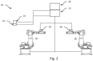
- Fig. 2 shows a schematic representation of a safety control system (10) according to the invention, wherein in this embodiment the display device (16) is formed by a signaling means (16), in particular a color-changing LED light ring (16) on the housing of the safety input means (14).
- a signaling means (16) in particular a color-changing LED light ring (16) on the housing of the safety input means (14).
- color-changing second signaling means in particular color-changing, luminous LED signal lights (24, 26), are attached to the automation system components (18, 20).
- Fig. 3 shows a schematic representation of a safety control system (10), wherein the second signaling means (24, 26) are passive light reflectors (24, 26), and a light projector (28) is provided at a suitable location in the automation system, which can irradiate the passive light reflectors (24, 26) with light.
- Fig. 4 shows the step-by-step sequence of the method according to the invention for all the above-mentioned embodiments.
- a first step (S1) the safety controller (12) determines a first automation system component (18) connected to it. This is done by exchanging data between the safety controller (12) and the individual automation system components (18) or with the automation system controller (22), which has knowledge of the status of the individual automation system components (18).
- the safety controller (12) can now visualize the effective range of the safety function by graphically displaying the automation system component (18) as an image or graphic model on the screen (16).
- the safety controller (12) visualizes the effective range of the safety function by simultaneously activating the LED light ring (16) on the housing of the safety input means (14) and the LED signal light (24) of the automation system component (18).
- the light reflector (24) of the automation system component (18) is illuminated by the light projector (28) in a color identical to the LED light ring (16).
- a further automation system component (20) is actively connected to the safety control (12) by the system operator or commissioning engineer or automatically by the automation system control (22)
- the safety control (12) updates the visualization of the current effective range on the screen (16) in such a way that the image of the further automation system component (20) is displayed in addition to the image of the existing automation system component (18). This symbolizes to the system operator that the safety function of the safety input means (14) now acts on the combination of automation system components (18, 20).
- the safety controller (12) updates the visualization of the current effective range by the LED signal light (26) of the automation system component (20) with the identical color of the LED light ring (16) on the housing of the safety input device (14) and the LED signal light (24) of the previous automation system component (18) is activated.
- the light reflector (26) with the identical color of the LED light ring (16) on the housing of the safety input device (14) and the light reflector (24) of the previous automation system component (18) is illuminated by the light projector (28).
- a third step (S3) which can be an alternative or supplementary to the previous second step, the automation system component (18, 20) is actively separated from the safety controller (12) by the system operator or commissioning engineer or automatically by the automation system controller (22), the safety controller (12) in the first embodiment updates the visualization of the current effective area on the screen (16) in such a way that the image of this automation system component (18, 20) is removed there. The system operator can thus see that the safety function of the safety input means (14) no longer affects the automation system component (18, 20).
- the safety controller (12) updates the visualization of the current effective range by switching off the LED light ring (16) and the LED signal light (24), or by switching off the illumination of the light reflector (24) by the light projector (28).
Landscapes
- Engineering & Computer Science (AREA)
- Physics & Mathematics (AREA)
- General Physics & Mathematics (AREA)
- Automation & Control Theory (AREA)
- Robotics (AREA)
- Mechanical Engineering (AREA)
- Human Computer Interaction (AREA)
- Manufacturing & Machinery (AREA)
- Safety Devices In Control Systems (AREA)
- Testing And Monitoring For Control Systems (AREA)
Claims (4)
- Système de commande de sécurité (10) permettant d'exécuter une fonction de sécurité pour au moins un composant d'installation d'automatisation (18, 20), dans lequel le système de commande de sécurité (10) présente une commande de sécurité (12) et un ou plusieurs moyens d'entrée de sécurité (14), et dans lequel l'exécution de la fonction de sécurité est déclenchée par l'actionnement d'un des moyens d'entrée de sécurité (14), dans lequel un dispositif d'affichage (16) est disposé au niveau de chaque moyen d'entrée de sécurité (14), dans lequel le dispositif d'affichage (16) est conçu pour visualiser une zone active de la fonction de sécurité en fonction d'une configuration de sécurité prédéfinie de la commande de sécurité (12) lorsque le composant d'installation d'automatisation (18, 20) est connecté à la commande de sécurité (12), dans lequel le dispositif d'affichage (16) est un premier moyen de signalisation de couleur variable, et
caractérisé en ce qu'un ou plusieurs deuxièmes moyens de signalisation (24, 26) de couleur variable sont associés au composant d'installation d'automatisation (18, 20), et en ce que le premier et ledit un ou les plusieurs deuxièmes moyens de signalisation (24, 26) visualisent la zone active de la fonction de sécurité en ce que le premier moyen de signalisation et ledit un ou les plusieurs deuxièmes moyens de signalisation coïncident au niveau des couleurs. - Système de commande de sécurité (10) selon la revendication 1, caractérisé en ce que la commande de sécurité (12) sert de commande de sécurité centrale, et le composant d'installation d'automatisation comprend une commande de sécurité locale, dans lequel la commande de sécurité centrale est connectée à la commande de sécurité locale des composants d'installation d'automatisation.
- Procédé permettant d'exécuter une fonction de sécurité pour au moins un composant d'installation d'automatisation (18, 20) au moyen d'une commande de sécurité (12) et d'un ou de plusieurs moyens d'entrée de sécurité (14), dans lequel l'exécution de la fonction de sécurité est déclenchée par l'actionnement d'un des moyens d'entrée de sécurité (14), et un dispositif d'affichage (16) est disposé au niveau du moyen d'entrée de sécurité (14), présentant les étapes consistant à- prédéfinir une configuration de sécurité pour la commande de sécurité (12),- déterminer le composant d'installation d'automatisation (18, 20) qui est connecté à la commande de sécurité (12) ;- visualiser la zone active de la fonction de sécurité sur ou par le dispositif d'affichage (16) en fonction de la configuration de sécurité prédéfinie, dans lequel le dispositif d'affichage (16) est un premier moyen de signalisation de couleur variable,caractérisé en ce qu'un ou plusieurs deuxièmes moyens de signalisation (24, 26) de couleur variable sont associés au composant d'installation d'automatisation (18, 20), et en ce que la visualisation de la zone active de la fonction de sécurité est effectuée par une coïncidence des couleurs des premiers et des deuxièmes moyens de signalisation.
- Procédé permettant d'exécuter une fonction de sécurité selon la revendication 3, caractérisé en outre par l'étape consistant à- mettre à jour la visualisation par le dispositif d'affichage (16) en fonction de la configuration de sécurité spécifiée si le composant d'installation d'automatisation (18, 20) est connecté à la commande de sécurité (12) ou est déconnecté de la commande de sécurité (12).
Applications Claiming Priority (2)
| Application Number | Priority Date | Filing Date | Title |
|---|---|---|---|
| DE102020115104.7A DE102020115104A1 (de) | 2020-06-08 | 2020-06-08 | Sicherheitssteuerungssystem und Verfahren zum Ausführen einer Sicherheitsfunktion |
| PCT/EP2021/063824 WO2021249757A1 (fr) | 2020-06-08 | 2021-05-25 | Système de commande de sécurité et procédé d'exécution d'une fonction de sécurité |
Publications (2)
| Publication Number | Publication Date |
|---|---|
| EP4162330A1 EP4162330A1 (fr) | 2023-04-12 |
| EP4162330B1 true EP4162330B1 (fr) | 2025-01-01 |
Family
ID=76181128
Family Applications (1)
| Application Number | Title | Priority Date | Filing Date |
|---|---|---|---|
| EP21728532.9A Active EP4162330B1 (fr) | 2020-06-08 | 2021-05-25 | Système de commande de sécurité et procédé d'exécution d'une fonction de sécurité |
Country Status (3)
| Country | Link |
|---|---|
| EP (1) | EP4162330B1 (fr) |
| DE (1) | DE102020115104A1 (fr) |
| WO (1) | WO2021249757A1 (fr) |
Families Citing this family (2)
| Publication number | Priority date | Publication date | Assignee | Title |
|---|---|---|---|---|
| DE102022111226B3 (de) | 2022-05-05 | 2023-07-27 | Franka Emika Gmbh | Gekapselte Sicherheit für den Betrieb eines Robotermanipulators |
| DE102022112439B3 (de) | 2022-05-05 | 2023-07-27 | Franka Emika Gmbh | Sicherer Roboter |
Family Cites Families (6)
| Publication number | Priority date | Publication date | Assignee | Title |
|---|---|---|---|---|
| DE602005006531D1 (de) * | 2005-04-19 | 2008-06-19 | Comau Spa | Verfahren zur Steuerung von industriellen Robotern und entsprechend gesteuerte Roboter, Robotersysteme und Computerprogramme |
| ATE509305T1 (de) * | 2008-03-07 | 2011-05-15 | Sick Ag | Verfahren und vorrichtung zum programmieren und/oder konfigurieren einer sicherheitssteuerung |
| DE102010017857B4 (de) | 2010-04-22 | 2019-08-08 | Sick Ag | 3D-Sicherheitsvorrichtung und Verfahren zur Absicherung und Bedienung mindestens einer Maschine |
| US10338557B2 (en) * | 2017-06-19 | 2019-07-02 | Rockwell Automation Technologies, Inc. | Systems and methods for safety input devices |
| AT521872A1 (de) | 2018-10-31 | 2020-05-15 | Keba Ag | Verfahren zum Betreiben eines Maschinensteuerungssystems sowie entsprechendes Maschinensteuerungssystem |
| AT521871B1 (de) | 2018-10-31 | 2021-10-15 | Keba Ag | Verfahren zum Betreiben eines Maschinensteuerungssystems sowie Maschinensteuerungssystem |
-
2020
- 2020-06-08 DE DE102020115104.7A patent/DE102020115104A1/de active Pending
-
2021
- 2021-05-25 EP EP21728532.9A patent/EP4162330B1/fr active Active
- 2021-05-25 WO PCT/EP2021/063824 patent/WO2021249757A1/fr not_active Ceased
Also Published As
| Publication number | Publication date |
|---|---|
| EP4162330A1 (fr) | 2023-04-12 |
| DE102020115104A1 (de) | 2021-12-09 |
| WO2021249757A1 (fr) | 2021-12-16 |
Similar Documents
| Publication | Publication Date | Title |
|---|---|---|
| DE10110776B4 (de) | Verfahren zur Zuordnung einer mobilen Bedien- und/oder Beobachtungseinrichtung zu einer Maschine sowie Bedien- und/oder Beobachtungseinrichtung hierfür | |
| EP2317410B1 (fr) | Commande de sécurité | |
| EP3961318B1 (fr) | Procédé de configuration d'un dispositif modulaire de commutation de sécurité | |
| EP1890210A1 (fr) | Procédé et dispositif destinés au marquage de l'état de fonctionnement d'un élément de commande | |
| EP2678745B1 (fr) | Procédé d'installation d'un dispositif de transport | |
| EP3451087B1 (fr) | Système et procédé de sélection et d'identification des appareils de terrain | |
| EP4162330B1 (fr) | Système de commande de sécurité et procédé d'exécution d'une fonction de sécurité | |
| EP3873702B1 (fr) | Procédé de fonctionnement d'un système de commande de machine et système de commande de machine | |
| EP3889981B1 (fr) | Système de commande d'installations commandées électriquement | |
| EP2098926A1 (fr) | Procédé et dispositif adaptés à la programmation et/ou la configuration d'un contrôleur de sécurité | |
| EP2367083A1 (fr) | Dispositif de création d'un programme pour une commande programmable par mémoire, dispositif de programmation et procédé de programmation d'une commande programmable par mémoire | |
| EP3192091A1 (fr) | Interrupteur d'arrêt d'urgence adaptable contrôlé | |
| WO2020087099A1 (fr) | Procédé servant à faire fonctionner un système de commande de machine et système de commande de machine correspondant | |
| EP3969970A1 (fr) | Procédé de représentation et de commande de moyens de production, en particulier pour l'industrie de transformation des plastiques | |
| WO2005036492A1 (fr) | Systeme hmi dote d'un appareil de commande et d'observation mobile pour des commandes de securite d'une installation technique | |
| AT518665B1 (de) | Steuerungssystem für elektrisch gesteuerte Anlagen | |
| EP0623878A2 (fr) | Dispositif d'affichage pour système de bus d'installation | |
| LU503513B1 (de) | Bedieneinheit und Verfahren zum Bedienen einer Anlage mit einer Bedieneinheit | |
| DE19940874B4 (de) | Verfahren zum Konfigurieren eines sicheren Busteilnehmers und sicheres Steuerungssystem mit einem solchen | |
| WO2023110490A1 (fr) | Procédé d'affectation de fonctionnalité d'arrêt d'urgence et système d'automatisation | |
| EP2490086B1 (fr) | Procédé de fonctionnement de systèmes d'automatisation et programme informatique fonctionnant selon ce procédé | |
| EP3660597B1 (fr) | Dispositif pour une commutation d'un système de machine dangereuse | |
| AT521873B1 (de) | Industrielles Steuerungssystem | |
| DE202024105124U1 (de) | System mit elektronischen Bauteilen | |
| DE202013103586U1 (de) | Vorrichtung zum Konfigurieren und/oder Programmieren einer Sicherheitssteuerung |
Legal Events
| Date | Code | Title | Description |
|---|---|---|---|
| STAA | Information on the status of an ep patent application or granted ep patent |
Free format text: STATUS: UNKNOWN |
|
| STAA | Information on the status of an ep patent application or granted ep patent |
Free format text: STATUS: THE INTERNATIONAL PUBLICATION HAS BEEN MADE |
|
| PUAI | Public reference made under article 153(3) epc to a published international application that has entered the european phase |
Free format text: ORIGINAL CODE: 0009012 |
|
| STAA | Information on the status of an ep patent application or granted ep patent |
Free format text: STATUS: REQUEST FOR EXAMINATION WAS MADE |
|
| 17P | Request for examination filed |
Effective date: 20221222 |
|
| AK | Designated contracting states |
Kind code of ref document: A1 Designated state(s): AL AT BE BG CH CY CZ DE DK EE ES FI FR GB GR HR HU IE IS IT LI LT LU LV MC MK MT NL NO PL PT RO RS SE SI SK SM TR |
|
| P01 | Opt-out of the competence of the unified patent court (upc) registered |
Effective date: 20230528 |
|
| DAV | Request for validation of the european patent (deleted) | ||
| DAX | Request for extension of the european patent (deleted) | ||
| GRAP | Despatch of communication of intention to grant a patent |
Free format text: ORIGINAL CODE: EPIDOSNIGR1 |
|
| STAA | Information on the status of an ep patent application or granted ep patent |
Free format text: STATUS: GRANT OF PATENT IS INTENDED |
|
| INTG | Intention to grant announced |
Effective date: 20240814 |
|
| GRAS | Grant fee paid |
Free format text: ORIGINAL CODE: EPIDOSNIGR3 |
|
| GRAA | (expected) grant |
Free format text: ORIGINAL CODE: 0009210 |
|
| STAA | Information on the status of an ep patent application or granted ep patent |
Free format text: STATUS: THE PATENT HAS BEEN GRANTED |
|
| AK | Designated contracting states |
Kind code of ref document: B1 Designated state(s): AL AT BE BG CH CY CZ DE DK EE ES FI FR GB GR HR HU IE IS IT LI LT LU LV MC MK MT NL NO PL PT RO RS SE SI SK SM TR |
|
| REG | Reference to a national code |
Ref country code: GB Ref legal event code: FG4D Free format text: NOT ENGLISH |
|
| REG | Reference to a national code |
Ref country code: CH Ref legal event code: EP |
|
| REG | Reference to a national code |
Ref country code: DE Ref legal event code: R096 Ref document number: 502021006279 Country of ref document: DE |
|
| REG | Reference to a national code |
Ref country code: IE Ref legal event code: FG4D Free format text: LANGUAGE OF EP DOCUMENT: GERMAN |
|
| REG | Reference to a national code |
Ref country code: LT Ref legal event code: MG9D |
|
| REG | Reference to a national code |
Ref country code: NL Ref legal event code: MP Effective date: 20250101 |
|
| PG25 | Lapsed in a contracting state [announced via postgrant information from national office to epo] |
Ref country code: NL Free format text: LAPSE BECAUSE OF FAILURE TO SUBMIT A TRANSLATION OF THE DESCRIPTION OR TO PAY THE FEE WITHIN THE PRESCRIBED TIME-LIMIT Effective date: 20250101 |
|
| PG25 | Lapsed in a contracting state [announced via postgrant information from national office to epo] |
Ref country code: FI Free format text: LAPSE BECAUSE OF FAILURE TO SUBMIT A TRANSLATION OF THE DESCRIPTION OR TO PAY THE FEE WITHIN THE PRESCRIBED TIME-LIMIT Effective date: 20250101 |
|
| PG25 | Lapsed in a contracting state [announced via postgrant information from national office to epo] |
Ref country code: PL Free format text: LAPSE BECAUSE OF FAILURE TO SUBMIT A TRANSLATION OF THE DESCRIPTION OR TO PAY THE FEE WITHIN THE PRESCRIBED TIME-LIMIT Effective date: 20250101 |
|
| PGFP | Annual fee paid to national office [announced via postgrant information from national office to epo] |
Ref country code: DE Payment date: 20250402 Year of fee payment: 5 |
|
| PG25 | Lapsed in a contracting state [announced via postgrant information from national office to epo] |
Ref country code: ES Free format text: LAPSE BECAUSE OF FAILURE TO SUBMIT A TRANSLATION OF THE DESCRIPTION OR TO PAY THE FEE WITHIN THE PRESCRIBED TIME-LIMIT Effective date: 20250101 |
|
| PG25 | Lapsed in a contracting state [announced via postgrant information from national office to epo] |
Ref country code: IS Free format text: LAPSE BECAUSE OF FAILURE TO SUBMIT A TRANSLATION OF THE DESCRIPTION OR TO PAY THE FEE WITHIN THE PRESCRIBED TIME-LIMIT Effective date: 20250501 Ref country code: NO Free format text: LAPSE BECAUSE OF FAILURE TO SUBMIT A TRANSLATION OF THE DESCRIPTION OR TO PAY THE FEE WITHIN THE PRESCRIBED TIME-LIMIT Effective date: 20250401 |
|
| PG25 | Lapsed in a contracting state [announced via postgrant information from national office to epo] |
Ref country code: HR Free format text: LAPSE BECAUSE OF FAILURE TO SUBMIT A TRANSLATION OF THE DESCRIPTION OR TO PAY THE FEE WITHIN THE PRESCRIBED TIME-LIMIT Effective date: 20250101 |
|
| PG25 | Lapsed in a contracting state [announced via postgrant information from national office to epo] |
Ref country code: PT Free format text: LAPSE BECAUSE OF FAILURE TO SUBMIT A TRANSLATION OF THE DESCRIPTION OR TO PAY THE FEE WITHIN THE PRESCRIBED TIME-LIMIT Effective date: 20250502 Ref country code: LV Free format text: LAPSE BECAUSE OF FAILURE TO SUBMIT A TRANSLATION OF THE DESCRIPTION OR TO PAY THE FEE WITHIN THE PRESCRIBED TIME-LIMIT Effective date: 20250101 |
|
| PGFP | Annual fee paid to national office [announced via postgrant information from national office to epo] |
Ref country code: FR Payment date: 20250401 Year of fee payment: 5 |
|
| PG25 | Lapsed in a contracting state [announced via postgrant information from national office to epo] |
Ref country code: BG Free format text: LAPSE BECAUSE OF FAILURE TO SUBMIT A TRANSLATION OF THE DESCRIPTION OR TO PAY THE FEE WITHIN THE PRESCRIBED TIME-LIMIT Effective date: 20250101 Ref country code: GR Free format text: LAPSE BECAUSE OF FAILURE TO SUBMIT A TRANSLATION OF THE DESCRIPTION OR TO PAY THE FEE WITHIN THE PRESCRIBED TIME-LIMIT Effective date: 20250402 |
|
| PGFP | Annual fee paid to national office [announced via postgrant information from national office to epo] |
Ref country code: CH Payment date: 20250601 Year of fee payment: 5 |
|
| PGFP | Annual fee paid to national office [announced via postgrant information from national office to epo] |
Ref country code: AT Payment date: 20250721 Year of fee payment: 5 |
|
| PG25 | Lapsed in a contracting state [announced via postgrant information from national office to epo] |
Ref country code: CZ Free format text: LAPSE BECAUSE OF FAILURE TO SUBMIT A TRANSLATION OF THE DESCRIPTION OR TO PAY THE FEE WITHIN THE PRESCRIBED TIME-LIMIT Effective date: 20250101 |
|
| PG25 | Lapsed in a contracting state [announced via postgrant information from national office to epo] |
Ref country code: SE Free format text: LAPSE BECAUSE OF FAILURE TO SUBMIT A TRANSLATION OF THE DESCRIPTION OR TO PAY THE FEE WITHIN THE PRESCRIBED TIME-LIMIT Effective date: 20250101 |
|
| REG | Reference to a national code |
Ref country code: DE Ref legal event code: R097 Ref document number: 502021006279 Country of ref document: DE |
|
| PG25 | Lapsed in a contracting state [announced via postgrant information from national office to epo] |
Ref country code: SM Free format text: LAPSE BECAUSE OF FAILURE TO SUBMIT A TRANSLATION OF THE DESCRIPTION OR TO PAY THE FEE WITHIN THE PRESCRIBED TIME-LIMIT Effective date: 20250101 |
|
| PG25 | Lapsed in a contracting state [announced via postgrant information from national office to epo] |
Ref country code: DK Free format text: LAPSE BECAUSE OF FAILURE TO SUBMIT A TRANSLATION OF THE DESCRIPTION OR TO PAY THE FEE WITHIN THE PRESCRIBED TIME-LIMIT Effective date: 20250101 |
|
| PG25 | Lapsed in a contracting state [announced via postgrant information from national office to epo] |
Ref country code: IT Free format text: LAPSE BECAUSE OF FAILURE TO SUBMIT A TRANSLATION OF THE DESCRIPTION OR TO PAY THE FEE WITHIN THE PRESCRIBED TIME-LIMIT Effective date: 20250101 |
|
| PG25 | Lapsed in a contracting state [announced via postgrant information from national office to epo] |
Ref country code: EE Free format text: LAPSE BECAUSE OF FAILURE TO SUBMIT A TRANSLATION OF THE DESCRIPTION OR TO PAY THE FEE WITHIN THE PRESCRIBED TIME-LIMIT Effective date: 20250101 |
|
| PG25 | Lapsed in a contracting state [announced via postgrant information from national office to epo] |
Ref country code: RO Free format text: LAPSE BECAUSE OF FAILURE TO SUBMIT A TRANSLATION OF THE DESCRIPTION OR TO PAY THE FEE WITHIN THE PRESCRIBED TIME-LIMIT Effective date: 20250101 |
|
| PG25 | Lapsed in a contracting state [announced via postgrant information from national office to epo] |
Ref country code: SK Free format text: LAPSE BECAUSE OF FAILURE TO SUBMIT A TRANSLATION OF THE DESCRIPTION OR TO PAY THE FEE WITHIN THE PRESCRIBED TIME-LIMIT Effective date: 20250101 |
|
| PLBE | No opposition filed within time limit |
Free format text: ORIGINAL CODE: 0009261 |
|
| STAA | Information on the status of an ep patent application or granted ep patent |
Free format text: STATUS: NO OPPOSITION FILED WITHIN TIME LIMIT |
|
| 26N | No opposition filed |
Effective date: 20251002 |
|
| PG25 | Lapsed in a contracting state [announced via postgrant information from national office to epo] |
Ref country code: LU Free format text: LAPSE BECAUSE OF NON-PAYMENT OF DUE FEES Effective date: 20250525 |
|
| REG | Reference to a national code |
Ref country code: BE Ref legal event code: MM Effective date: 20250531 |
|
| PG25 | Lapsed in a contracting state [announced via postgrant information from national office to epo] |
Ref country code: MC Free format text: LAPSE BECAUSE OF FAILURE TO SUBMIT A TRANSLATION OF THE DESCRIPTION OR TO PAY THE FEE WITHIN THE PRESCRIBED TIME-LIMIT Effective date: 20250101 |
|
| PGFP | Annual fee paid to national office [announced via postgrant information from national office to epo] |
Ref country code: GB Payment date: 20260312 Year of fee payment: 6 |
|
| PG25 | Lapsed in a contracting state [announced via postgrant information from national office to epo] |
Ref country code: IE Free format text: LAPSE BECAUSE OF NON-PAYMENT OF DUE FEES Effective date: 20250525 |
|
| PG25 | Lapsed in a contracting state [announced via postgrant information from national office to epo] |
Ref country code: BE Free format text: LAPSE BECAUSE OF NON-PAYMENT OF DUE FEES Effective date: 20250531 |