EP4162845A1 - Dispositif de préparation d'une boisson - Google Patents
Dispositif de préparation d'une boisson Download PDFInfo
- Publication number
- EP4162845A1 EP4162845A1 EP22200639.7A EP22200639A EP4162845A1 EP 4162845 A1 EP4162845 A1 EP 4162845A1 EP 22200639 A EP22200639 A EP 22200639A EP 4162845 A1 EP4162845 A1 EP 4162845A1
- Authority
- EP
- European Patent Office
- Prior art keywords
- capsule
- receptacle
- container
- holder
- closure element
- Prior art date
- Legal status (The legal status is an assumption and is not a legal conclusion. Google has not performed a legal analysis and makes no representation as to the accuracy of the status listed.)
- Withdrawn
Links
- 235000013361 beverage Nutrition 0.000 title claims abstract description 15
- 239000002775 capsule Substances 0.000 claims abstract description 41
- XLYOFNOQVPJJNP-UHFFFAOYSA-N water Substances O XLYOFNOQVPJJNP-UHFFFAOYSA-N 0.000 claims abstract description 29
- 238000010438 heat treatment Methods 0.000 claims abstract description 15
- 239000000463 material Substances 0.000 claims abstract description 8
- 238000000605 extraction Methods 0.000 claims abstract description 6
- 238000009423 ventilation Methods 0.000 claims description 8
- 238000007789 sealing Methods 0.000 claims description 6
- 230000005611 electricity Effects 0.000 claims 1
- 239000007788 liquid Substances 0.000 abstract description 2
- 238000013124 brewing process Methods 0.000 description 12
- 241001122767 Theaceae Species 0.000 description 6
- 230000003287 optical effect Effects 0.000 description 6
- 238000001514 detection method Methods 0.000 description 5
- 230000035622 drinking Effects 0.000 description 5
- 238000005192 partition Methods 0.000 description 5
- 235000013353 coffee beverage Nutrition 0.000 description 3
- 238000002360 preparation method Methods 0.000 description 3
- 241000047428 Halter Species 0.000 description 2
- 235000012171 hot beverage Nutrition 0.000 description 2
- 208000027418 Wounds and injury Diseases 0.000 description 1
- 238000004140 cleaning Methods 0.000 description 1
- 230000006378 damage Effects 0.000 description 1
- 230000003670 easy-to-clean Effects 0.000 description 1
- 239000012530 fluid Substances 0.000 description 1
- 239000008236 heating water Substances 0.000 description 1
- 208000014674 injury Diseases 0.000 description 1
- 238000000034 method Methods 0.000 description 1
- 230000000149 penetrating effect Effects 0.000 description 1
- 210000004894 snout Anatomy 0.000 description 1
- 230000000007 visual effect Effects 0.000 description 1
Images


Classifications
-
- A—HUMAN NECESSITIES
- A47—FURNITURE; DOMESTIC ARTICLES OR APPLIANCES; COFFEE MILLS; SPICE MILLS; SUCTION CLEANERS IN GENERAL
- A47J—KITCHEN EQUIPMENT; COFFEE MILLS; SPICE MILLS; APPARATUS FOR MAKING BEVERAGES
- A47J31/00—Apparatus for making beverages
- A47J31/16—Inverting coffee-making apparatus in which water is boiled in the lower part and the apparatus is subsequently inverted to pass the water through the filter
-
- A—HUMAN NECESSITIES
- A47—FURNITURE; DOMESTIC ARTICLES OR APPLIANCES; COFFEE MILLS; SPICE MILLS; SUCTION CLEANERS IN GENERAL
- A47J—KITCHEN EQUIPMENT; COFFEE MILLS; SPICE MILLS; APPARATUS FOR MAKING BEVERAGES
- A47J31/00—Apparatus for making beverages
- A47J31/005—Portable or compact beverage making apparatus, e.g. for travelling, for use in automotive vehicles
-
- A—HUMAN NECESSITIES
- A47—FURNITURE; DOMESTIC ARTICLES OR APPLIANCES; COFFEE MILLS; SPICE MILLS; SUCTION CLEANERS IN GENERAL
- A47J—KITCHEN EQUIPMENT; COFFEE MILLS; SPICE MILLS; APPARATUS FOR MAKING BEVERAGES
- A47J31/00—Apparatus for making beverages
- A47J31/44—Parts or details or accessories of beverage-making apparatus
- A47J31/4403—Constructional details
-
- A—HUMAN NECESSITIES
- A47—FURNITURE; DOMESTIC ARTICLES OR APPLIANCES; COFFEE MILLS; SPICE MILLS; SUCTION CLEANERS IN GENERAL
- A47J—KITCHEN EQUIPMENT; COFFEE MILLS; SPICE MILLS; APPARATUS FOR MAKING BEVERAGES
- A47J31/00—Apparatus for making beverages
- A47J31/44—Parts or details or accessories of beverage-making apparatus
- A47J31/4492—Means to read code provided on ingredient pod or cartridge
Definitions
- the present invention relates to a device for preparing a beverage, having a container with a lower part for holding water, a heating device for heating the water in the lower part, and a removable upper part with a receptacle for inserting a capsule with extraction material, the container for Brewing a drink can be parked on the upper part arranged below in this position, so that hot water flows into the capsule.
- a container with an upper part and a lower part wherein a heating device for heating water is provided in the lower part and a filter element for tea is provided in the upper part.
- a heating device for heating water is provided in the lower part
- a filter element for tea is provided in the upper part.
- the WO 2020/030329 A1 discloses an apparatus and method for preparing a beverage in which a receptacle for inserting a capsule is provided on a detachable top. This makes handling easier as the container is inverted for the preparation until the required brewing time has been reached, and then the container can be inverted again and the drink removed. Although cleaning is made easier by removing the capsule, the container is not suitable as a drinking vessel, particularly for driving in vehicles, which require a splash guard, especially for hot drinks.
- U.S. 3,181,951 discloses a container for brewing coffee, in which a container for ground coffee can be fixed to a lid via magnets. By rotating the container, the container can be flushed with hot water to make a coffee drink.
- the container comprises a lower part for receiving water and an upper part, which has a seat for inserting a capsule with extraction material, a tubular channel for removing the beverage being formed adjacent to this seat, which can be closed by a closure element.
- the container with the upper part mounted on the lower part can be sealed off from the environment, so that the container can be carried along for transport.
- the closure element can then be moved into an open position in order to pour the beverage out through the tubular channel or to drink it directly from a spout. This improves handling of the container and reduces the risk of injury from a hot brewed beverage.
- the tubular channel is preferably formed entirely within the top and not in the space between the bottom and top.
- the tubular channel extends substantially vertically from a bottom of the top to a top. This makes it easy to clean the canal.
- the channel does not have to extend over the entire height of the upper part, but preferably has an inlet in the area of a partition wall on the upper part up to a ceiling in the upper area of the upper part.
- the closure element can then be arranged on the cover of the upper part.
- the tubular channel in the upper part preferably has a volume of less than 10 cm 3 , in particular between 1 cm 3 and 6 cm 3 . This ensures that only a little water flows into the channel during the brewing process, since this water does not take part in the brewing process. Most of the volume of hot water can be in fluid communication with the extraction material during the brewing process, where the top is placed on a base and is thus located at the bottom. As a result, the proportion of hot water that cannot get into the capsule due to the flow conditions during the brewing process is quite small and does not affect the taste experience.
- a ventilation channel is formed in the upper part adjacent to the receptacle for the capsule and adjacent to the tubular channel. This allows pressure to equalize when drinking when the volume of the drink is reduced.
- the ventilation duct can preferably be closed via the closure element, which also closes the tubular duct, so that both the tubular duct and the ventilation duct can be opened and closed with a movement of the closure element.
- the closure element is designed as a pivotable cover for easy handling.
- the closure element can be latched both in an open position and in a closed position, for example in different angular positions.
- the cover can be arranged on the upper side of the upper part.
- a holder is preferably provided on the upper part, by means of which the capsule can be fixed in the receptacle, which is preferably designed in the shape of a cup.
- the holder can be mounted pivotably on the upper part and allow a capsule to be removed and inserted in an open position, while the capsule is fixed in the receptacle in a closed position.
- a fixing device can be provided on the upper part and the holder, which holds the capsule in the inserted position, the fixing device preferably comprising at least one magnet.
- At least one magnet is preferably provided both on the upper part and on the holder.
- mechanical fixing elements for example latching webs, can also be provided in order to fix the holder in a closed position.
- a sealing ring can be provided around the receptacle on the upper part, on which an edge of the capsule can be placed.
- the capsule can be pressed against the sealing ring at the edge by the holder, which ensures a reliable seal.
- the receptacle can remain clean, and in particular sensor devices can be provided for identifying the capsule, for example optical detection means which are provided in the bottom area of the capsule.
- a circuit board with a controller is preferably provided in the upper part, which is connected to a sensor, for example, in order to identify the type of capsule.
- a sensor for example, in order to identify the type of capsule.
- the water temperature and/or brewing time can be controlled.
- the brewing time can be displayed, for example, via acoustic or visual detection means, so that the user knows when the container needs to be rotated again.
- the optical and acoustic detection means can optionally be installed in the upper part, so that the container can also be positioned at a distance from a base station during the brewing process.
- the device preferably also comprises a base station on which the container can be placed and removed, the base station having plug-in contacts in order to supply the heating device with power.
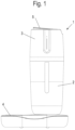
- a device for preparing a drink comprises a container 1 which is placed on a base station 4 .
- the container 1 comprises a lower part 2 for holding water and an upper part 3 which is detachably fixed to the lower part 2 is.
- a closure element 5 in the form of a cover is provided on the upper part 3 .
- the lower part 2 comprises an inner cup 6 for holding water, which can be heated by a heating device 7 .
- the inner cup 6 is surrounded by an outer wall 8 of the base 2 so that the base 2 can be gripped on the outside of the wall 8 without the hot water in the cup 6 making it too hot to touch.
- the heating device 7 can heat the bottom of the cup 6 via heating loops or other heating elements and is supplied with power via the base station 4 , in particular via plug-in contacts, so that the container 1 can be removed from the base station 4 .
- the upper part 3 includes a receptacle 11 for a capsule containing extraction material, in particular tea.
- the capsule can be designed as in the document DE 10 2014 109 768 B4 is revealed.
- the interior of the capsule is accessible in the inserted position in the receptacle 11 via a sieve or other filter material, so that when the container 1 is inverted, hot water can flow into the capsule for a brewing process.
- a circuit board 32 with a controller and a detection device is provided on the upper part 3 in order to read out a coding of the capsule, so that the brewing time and/or the water temperature can be controlled.
- coding for an optical detection device can be provided on the base of the capsule, which is arranged adjacent to the circuit board 32 .
- tubular channel 14 Adjacent to the receptacle 11 there is a tubular channel 14 for taking out the drink.
- the tubular channel 14 extends from an underside of the upper part 3 to the closure element 5, which closes the channel 14 in the closed position and allows the prepared beverage to be poured out in the open position.
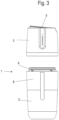
- FIG 3 the upper part 3 is shown in a removed position. It can be seen that the lower part 2 has a partition 9 with a socket between the outer wall 8 and the inner cup 6, on which a sealing ring 10 can be inserted in order to be able to mount the upper part 3 on the lower part 2 in a sealed manner. Cold water can be poured into the base 2 in the removed position.
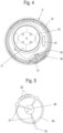
- FIG 4 the upper part 3 is shown from below, and it can be seen that the cup-shaped receptacle 11 is surrounded by an intermediate wall 12, an annular seal 13 being provided on the intermediate wall 12 around the receptacle 11.
- An inlet to the tubular channel 14 is provided on the intermediate wall 12, which has a cross section of, for example, less than 3 cm 2 so that the water flowing into the tubular channel 14 during a brewing process has only a small volume, since this does not or only slightly takes part in the brewing process.
- a ventilation channel 15 is provided at a distance from the receptacle 11 and the channel 14 , which extends from the underside of the upper part 3 to the upper side and can also be closed by the closure element 5 . Air can flow into the container 1 through the ventilation channel 15 when liquid is removed.
- a bearing 17 for a holder 19 is also formed on the intermediate wall 12 and is held on the bearing 17 in a pivotable manner.
- a ball element 18 is provided on the holder 19 which is rotatably arranged on the bearing 17 . It is also possible to provide another bearing with a pin or bolt on the upper part 3 to support the holder 19 in a pivotable manner.
- the holder 19 is in figure 5 shown in detail.
- the holder 19 comprises a ring from which a web with the ball element 18 protrudes on one side.
- One or more magnets 22 are provided on the opposite side, which are part of a fixing device in order to fix the holder 19 in a closed position on the upper part 3 .
- the magnets 22 can be cast into the material of the holder 19, in particular plastic.
- a plurality of spokes 21 extend in a curved contour from the ring of the holder 19 to a connecting element 20, so that the holder 19 is reinforced and can ensure a certain contact pressure.
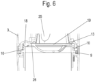
- the holder 19 is shown in an assembled position with a capsule 25 inserted into the receptacle 11.
- a rim 26 of the capsule 25 protrudes radially outwards and is pinched between the ring of the holder 19 and the annular seal 13 so that the space between the outside of the capsule and the inside of the receptacle 11 is sealed.
- One or more magnets can also be provided on the upper part 3, which interact with the magnets 22 on the holder 19 in order to hold the holder 19 in the closed position.
- Several can be distributed over the perimeter Magnets can be provided in order to press the capsule with the edge 26 against the seal 13 with a certain contact pressure.
- the partition wall 9 with the socket holds the sealing ring 10 against which an outer socket 23 of the upper part 3 rests, so that the upper part 3 and the lower part 2 are connected to one another in a sealed manner.
- mechanical locking means or latching means can be provided in order to hold the upper part 3 in the installed position on the lower part 2, for example via a bayonet lock.
- FIG 7 the upper part 3 is shown in a closed position.
- the tubular channel 14 is designed to be open at an inlet 27 but sealed at an outlet 28 in the upper area by a section 29 of the closure element 5 .
- Adjacent to the bottom of the receptacle 11 and the capsule is a circuit board 32 comprising a control to signal the end of a brewing process by optical or acoustic means.
- a loudspeaker 33 is mounted on the upper part 3, which indicates the end of the brewing time via acoustic signals.
- optical means can also be installed on the upper part 3 or lower part 2 .
- a position sensor is preferably also provided, by means of which the orientation of the container 1 can be detected, so that the start of the brewing process is automatically detected by turning the container 1 over.
- FIG 8 the upper part is shown with the closure element 5 open.
- the closure element 5 has been pivoted in relation to the closed position, for example by an angle of between 5° and 20°, so that the section 29 is lifted off the outlet 28 of the tubular channel 14 .
- the brewed beverage can now be routed via the tubular channel 14 to a spout 30 and optionally poured out or drunk directly.
- the closure element can preferably be latched in the closed position and in the open position in order to prevent accidental opening or closing.
- An actuating section 31 is provided on the closure element 5 on the side opposite the section 29 and is pressed for opening in order to pivot the closure element 5 into the open position. To close, the closure element 5 can be pressed back onto the upper part 3 from above.
- the upper part 3 is removed from the lower part 2 and the cup 6 is filled with water. Then the upper part 3 again mounted tightly on the lower part 2 and the preparation initiated by a control element, for example a push button on the lower part 2. As a result, the water in the cup 6 is heated to the desired temperature via the heating device 7 .
- the operating element also reads out the capsule 25 during identification, so that the brewing time and water temperature can be controlled depending on the type of tea.
- the container 1 After the water has been heated, the container 1 is inverted so that the top 3 is placed on a floor or base 4 . As a result, hot water can flow into the capsule 25 which is fixed in place by the holder 19 of the receptacle 11 .
- an optical and/or acoustic signal can be emitted so that the user turns the container 1 over again so that the lower part 2 is arranged at the bottom.
- the container 1 can now be carried along as a drink on transport routes, since the container 1 is sealed off from the outside and the hot drink in the cup 6 is arranged in a thermally insulated manner via the double-walled structure of the lower part 2 .
- the closure element 5 can be pivoted so that the drink can be drunk through the tubular channel 14 .
Landscapes
- Engineering & Computer Science (AREA)
- Food Science & Technology (AREA)
- Apparatus For Making Beverages (AREA)
Applications Claiming Priority (1)
| Application Number | Priority Date | Filing Date | Title |
|---|---|---|---|
| DE102021126311.5A DE102021126311A1 (de) | 2021-10-11 | 2021-10-11 | Vorrichtung zur Zubereitung eines Getränkes |
Publications (1)
| Publication Number | Publication Date |
|---|---|
| EP4162845A1 true EP4162845A1 (fr) | 2023-04-12 |
Family
ID=83689535
Family Applications (1)
| Application Number | Title | Priority Date | Filing Date |
|---|---|---|---|
| EP22200639.7A Withdrawn EP4162845A1 (fr) | 2021-10-11 | 2022-10-10 | Dispositif de préparation d'une boisson |
Country Status (2)
| Country | Link |
|---|---|
| EP (1) | EP4162845A1 (fr) |
| DE (1) | DE102021126311A1 (fr) |
Citations (7)
| Publication number | Priority date | Publication date | Assignee | Title |
|---|---|---|---|---|
| US3181951A (en) | 1960-09-28 | 1965-05-04 | George B Gronvold | Coffee brewing method |
| US20080060526A1 (en) * | 2006-09-13 | 2008-03-13 | Pacific Market International, Llc | Integrated beverage infuser and lid |
| US20110226133A1 (en) * | 2010-03-22 | 2011-09-22 | Tzu-Yuan Shen | Container with an improved structure |
| US9743796B2 (en) * | 2013-12-31 | 2017-08-29 | Brett C. Richardson | Portable coffee brewing device |
| CN107259928A (zh) | 2017-07-28 | 2017-10-20 | 泉州市范特西智能科技有限公司 | 一种分体式水杯 |
| DE102014109768B4 (de) | 2014-07-11 | 2019-01-24 | Melitta Single Portions Gmbh & Co. Kg | Vorrichtung zur Zubereitung von Brühgetränken, Kapsel, Kapselsystem und Verfahren zur Herstellung eines Brühgetränkes |
| WO2020030329A1 (fr) | 2018-08-09 | 2020-02-13 | Melitta Single Portions Gmbh & Co. Kg | Dispositif et procédé de préparation d'une boisson |
Family Cites Families (5)
| Publication number | Priority date | Publication date | Assignee | Title |
|---|---|---|---|---|
| US20100263545A1 (en) | 2009-04-17 | 2010-10-21 | Curt Morgan | Gas capsule powered coffee brewer |
| DE102011011204A1 (de) | 2010-05-28 | 2011-12-01 | Eugster/Frismag Ag | Brühvorrichtung zum Extrahieren einer Portionskapsel, Verfahren zum Betrieb einer Brühvorrichtung und Verwendung einer Brühvorrichtung |
| DE102011081712A1 (de) | 2011-08-29 | 2013-02-28 | BSH Bosch und Siemens Hausgeräte GmbH | Getränkeauslauf und Getränkespender |
| WO2013011154A2 (fr) | 2012-04-07 | 2013-01-24 | Blomus Gmbh | Dispositif de préparation d'une boisson, notamment de thé glacé |
| DE202012005191U1 (de) | 2012-05-25 | 2012-06-18 | SEVERIN ELEKTROGERÄTE GmbH | Vorrichtung zum Herstellen eines Getränkes |
-
2021
- 2021-10-11 DE DE102021126311.5A patent/DE102021126311A1/de not_active Withdrawn
-
2022
- 2022-10-10 EP EP22200639.7A patent/EP4162845A1/fr not_active Withdrawn
Patent Citations (7)
| Publication number | Priority date | Publication date | Assignee | Title |
|---|---|---|---|---|
| US3181951A (en) | 1960-09-28 | 1965-05-04 | George B Gronvold | Coffee brewing method |
| US20080060526A1 (en) * | 2006-09-13 | 2008-03-13 | Pacific Market International, Llc | Integrated beverage infuser and lid |
| US20110226133A1 (en) * | 2010-03-22 | 2011-09-22 | Tzu-Yuan Shen | Container with an improved structure |
| US9743796B2 (en) * | 2013-12-31 | 2017-08-29 | Brett C. Richardson | Portable coffee brewing device |
| DE102014109768B4 (de) | 2014-07-11 | 2019-01-24 | Melitta Single Portions Gmbh & Co. Kg | Vorrichtung zur Zubereitung von Brühgetränken, Kapsel, Kapselsystem und Verfahren zur Herstellung eines Brühgetränkes |
| CN107259928A (zh) | 2017-07-28 | 2017-10-20 | 泉州市范特西智能科技有限公司 | 一种分体式水杯 |
| WO2020030329A1 (fr) | 2018-08-09 | 2020-02-13 | Melitta Single Portions Gmbh & Co. Kg | Dispositif et procédé de préparation d'une boisson |
Also Published As
| Publication number | Publication date |
|---|---|
| DE102021126311A1 (de) | 2023-04-13 |
Similar Documents
| Publication | Publication Date | Title |
|---|---|---|
| DE60210227T2 (de) | Löffelförmige Kaffeebrühvorrichtung | |
| US5855160A (en) | Tea maker | |
| US7172705B2 (en) | Skimmer | |
| EP0162305B1 (fr) | Machine à café express | |
| US20200015619A1 (en) | French Press | |
| US7775152B2 (en) | Portafilter system for use with a rigid pod | |
| EP1468635B1 (fr) | Dispositif pour la préparation de boissons chaudes | |
| EP4090202B1 (fr) | Machine et procédé de préparation d'une boisson chaude | |
| EP4162845A1 (fr) | Dispositif de préparation d'une boisson | |
| EP3766391A1 (fr) | Dispositif de préparation du café | |
| DE19706523A1 (de) | Vorrichtung zur Zubereitung heißer, zu filternder Getränke | |
| DE19703076C1 (de) | Heimbraugerät | |
| EP3833226B1 (fr) | Dispositif et procédé de préparation d'une boisson | |
| DE2625650C2 (de) | Elektrische Kaffeemaschine | |
| DE4124993C2 (de) | Vorrichtung zum Zubereiten von Tee | |
| KR20200025149A (ko) | 핸드드립 커피추출기구 | |
| DE2344298A1 (de) | Kaffeemaschine | |
| JP2003061827A (ja) | 濾過飲料製造装置 | |
| EP4369997A1 (fr) | Machine automatique de préparation de boissons infusées et procédé de nettoyage d'une machine automatique de ce type | |
| DE102021134172B3 (de) | Verfahren und Vorrichtung zur Zubereitung eines Heißgetränks sowie dafür geeigneter Erweiterungs-Einsatz für eine Küchenmaschine | |
| JPH0317795Y2 (fr) | ||
| DE69002894T2 (de) | Deckel für Aufnahmebehälter für Infusionen. | |
| JPS5854021Y2 (ja) | コ−ヒ−抽出器 | |
| US624924A (en) | Coffee-pot | |
| DE838041C (de) | Elektrisch beheizte Maschine zur Herstellung von Brühgetränken, z. B. Kaffee |
Legal Events
| Date | Code | Title | Description |
|---|---|---|---|
| PUAI | Public reference made under article 153(3) epc to a published international application that has entered the european phase |
Free format text: ORIGINAL CODE: 0009012 |
|
| STAA | Information on the status of an ep patent application or granted ep patent |
Free format text: STATUS: THE APPLICATION HAS BEEN PUBLISHED |
|
| AK | Designated contracting states |
Kind code of ref document: A1 Designated state(s): AL AT BE BG CH CY CZ DE DK EE ES FI FR GB GR HR HU IE IS IT LI LT LU LV MC ME MK MT NL NO PL PT RO RS SE SI SK SM TR |
|
| STAA | Information on the status of an ep patent application or granted ep patent |
Free format text: STATUS: THE APPLICATION IS DEEMED TO BE WITHDRAWN |
|
| 18D | Application deemed to be withdrawn |
Effective date: 20231013 |