EP4162979A1 - Système de mise en uvre d'une thérapie photodynamique transcutanée (pdt) dans un organe ou un segment d'organe d'un corps organique - Google Patents
Système de mise en uvre d'une thérapie photodynamique transcutanée (pdt) dans un organe ou un segment d'organe d'un corps organique Download PDFInfo
- Publication number
- EP4162979A1 EP4162979A1 EP22193842.6A EP22193842A EP4162979A1 EP 4162979 A1 EP4162979 A1 EP 4162979A1 EP 22193842 A EP22193842 A EP 22193842A EP 4162979 A1 EP4162979 A1 EP 4162979A1
- Authority
- EP
- European Patent Office
- Prior art keywords
- light
- organ
- point
- grid
- template
- Prior art date
- Legal status (The legal status is an assumption and is not a legal conclusion. Google has not performed a legal analysis and makes no representation as to the accuracy of the status listed.)
- Pending
Links
- 210000000056 organ Anatomy 0.000 title claims abstract description 232
- 238000002428 photodynamic therapy Methods 0.000 title claims abstract description 73
- 238000003780 insertion Methods 0.000 claims abstract description 25
- 230000037431 insertion Effects 0.000 claims abstract description 25
- 230000005611 electricity Effects 0.000 claims abstract description 11
- 230000000295 complement effect Effects 0.000 claims description 3
- 238000006073 displacement reaction Methods 0.000 description 47
- 210000001519 tissue Anatomy 0.000 description 41
- 238000000034 method Methods 0.000 description 35
- 230000000694 effects Effects 0.000 description 21
- 230000003068 static effect Effects 0.000 description 21
- 230000001575 pathological effect Effects 0.000 description 20
- 230000035515 penetration Effects 0.000 description 15
- 238000013519 translation Methods 0.000 description 10
- 238000013507 mapping Methods 0.000 description 9
- 230000008901 benefit Effects 0.000 description 8
- 238000013461 design Methods 0.000 description 7
- 239000003504 photosensitizing agent Substances 0.000 description 7
- 230000008569 process Effects 0.000 description 6
- 230000008859 change Effects 0.000 description 5
- 238000003384 imaging method Methods 0.000 description 5
- 239000003550 marker Substances 0.000 description 5
- 239000000126 substance Substances 0.000 description 5
- 238000002560 therapeutic procedure Methods 0.000 description 5
- 206010028980 Neoplasm Diseases 0.000 description 4
- 239000013307 optical fiber Substances 0.000 description 4
- 230000000717 retained effect Effects 0.000 description 4
- 238000005253 cladding Methods 0.000 description 2
- 239000004020 conductor Substances 0.000 description 2
- 238000002360 preparation method Methods 0.000 description 2
- 238000001228 spectrum Methods 0.000 description 2
- 230000001225 therapeutic effect Effects 0.000 description 2
- 238000002604 ultrasonography Methods 0.000 description 2
- 230000000007 visual effect Effects 0.000 description 2
- 241001408627 Agriopis marginaria Species 0.000 description 1
- 230000009471 action Effects 0.000 description 1
- 238000000149 argon plasma sintering Methods 0.000 description 1
- 238000007630 basic procedure Methods 0.000 description 1
- 238000001574 biopsy Methods 0.000 description 1
- 230000015572 biosynthetic process Effects 0.000 description 1
- 230000008878 coupling Effects 0.000 description 1
- 238000010168 coupling process Methods 0.000 description 1
- 238000005859 coupling reaction Methods 0.000 description 1
- 230000002950 deficient Effects 0.000 description 1
- 230000001066 destructive effect Effects 0.000 description 1
- 230000008030 elimination Effects 0.000 description 1
- 238000003379 elimination reaction Methods 0.000 description 1
- 210000003238 esophagus Anatomy 0.000 description 1
- 239000004744 fabric Substances 0.000 description 1
- 230000002349 favourable effect Effects 0.000 description 1
- 210000000936 intestine Anatomy 0.000 description 1
- 230000003211 malignant effect Effects 0.000 description 1
- 239000000463 material Substances 0.000 description 1
- 238000013160 medical therapy Methods 0.000 description 1
- 239000002184 metal Substances 0.000 description 1
- 229910052760 oxygen Inorganic materials 0.000 description 1
- 239000001301 oxygen Substances 0.000 description 1
- 210000002307 prostate Anatomy 0.000 description 1
- 239000007787 solid Substances 0.000 description 1
- 230000007704 transition Effects 0.000 description 1
- 210000001835 viscera Anatomy 0.000 description 1
Images














Classifications
-
- A—HUMAN NECESSITIES
- A61—MEDICAL OR VETERINARY SCIENCE; HYGIENE
- A61N—ELECTROTHERAPY; MAGNETOTHERAPY; RADIATION THERAPY; ULTRASOUND THERAPY
- A61N5/00—Radiation therapy
- A61N5/06—Radiation therapy using light
- A61N5/0601—Apparatus for use inside the body
-
- A—HUMAN NECESSITIES
- A61—MEDICAL OR VETERINARY SCIENCE; HYGIENE
- A61N—ELECTROTHERAPY; MAGNETOTHERAPY; RADIATION THERAPY; ULTRASOUND THERAPY
- A61N5/00—Radiation therapy
- A61N5/06—Radiation therapy using light
-
- A—HUMAN NECESSITIES
- A61—MEDICAL OR VETERINARY SCIENCE; HYGIENE
- A61N—ELECTROTHERAPY; MAGNETOTHERAPY; RADIATION THERAPY; ULTRASOUND THERAPY
- A61N5/00—Radiation therapy
- A61N5/06—Radiation therapy using light
- A61N5/0613—Apparatus adapted for a specific treatment
- A61N5/062—Photodynamic therapy, i.e. excitation of an agent
-
- A—HUMAN NECESSITIES
- A61—MEDICAL OR VETERINARY SCIENCE; HYGIENE
- A61N—ELECTROTHERAPY; MAGNETOTHERAPY; RADIATION THERAPY; ULTRASOUND THERAPY
- A61N5/00—Radiation therapy
- A61N5/06—Radiation therapy using light
- A61N5/0601—Apparatus for use inside the body
- A61N2005/0612—Apparatus for use inside the body using probes penetrating tissue; interstitial probes
-
- A—HUMAN NECESSITIES
- A61—MEDICAL OR VETERINARY SCIENCE; HYGIENE
- A61N—ELECTROTHERAPY; MAGNETOTHERAPY; RADIATION THERAPY; ULTRASOUND THERAPY
- A61N5/00—Radiation therapy
- A61N5/06—Radiation therapy using light
- A61N2005/0635—Radiation therapy using light characterised by the body area to be irradiated
- A61N2005/0643—Applicators, probes irradiating specific body areas in close proximity
-
- A—HUMAN NECESSITIES
- A61—MEDICAL OR VETERINARY SCIENCE; HYGIENE
- A61N—ELECTROTHERAPY; MAGNETOTHERAPY; RADIATION THERAPY; ULTRASOUND THERAPY
- A61N5/00—Radiation therapy
- A61N5/06—Radiation therapy using light
- A61N2005/065—Light sources therefor
- A61N2005/0651—Diodes
-
- A—HUMAN NECESSITIES
- A61—MEDICAL OR VETERINARY SCIENCE; HYGIENE
- A61N—ELECTROTHERAPY; MAGNETOTHERAPY; RADIATION THERAPY; ULTRASOUND THERAPY
- A61N5/00—Radiation therapy
- A61N5/10—X-ray therapy; Gamma-ray therapy; Particle-irradiation therapy
- A61N5/1001—X-ray therapy; Gamma-ray therapy; Particle-irradiation therapy using radiation sources introduced into or applied onto the body; brachytherapy
- A61N5/1007—Arrangements or means for the introduction of sources into the body
- A61N2005/1012—Templates or grids for guiding the introduction of sources
Definitions
- the present disclosure relates to a system for performing transcutaneous photodynamic therapy (PDT) in an organ or organ segment of an organic body.
- PDT transcutaneous photodynamic therapy
- PDT is a well-known medical therapy of pathological tissue of a patient.
- the patient is administered a photosensitizer or marker substance, which accumulates selectively in the pathological tissue to be treated.
- light is then applied directly to or even into the pathological tissue by means of a light applicator or several light applicators in order to promote the formation of oxygen radicals by means of the locally limited enriched photosensitizer or marker substance and thereby the pathological tissue, such as a tumor, to destroy.
- laser light is coupled into a light guide and guided to the tissue.
- the therapy light can be coupled out relatively easily and radiated onto the pathological tissue surface.
- the pathological tissue extends over a volume in an internal organ or organ segment, a tumor cannot always be effectively irradiated from "outside” because of the limited penetration depth of the light into the tissue.
- the PDT is special effective when the light is irradiated from inside the pathological tissue volume. To do this, the light applicator or light applicators must be inserted into the pathological tissue.
- the U.S. 6,048,359 describes, for example, a system for performing transcutaneous PDT to irradiate an internal volume in a patient's body.
- a plurality of needle-like light applicators are pierced in parallel through the skin into the body, with each light applicator having lateral light outputs distributed over its length in order to irradiate a volume in the body.
- the disadvantage of the known solution is that the light applicators firstly have to be relatively thick and secondly are relatively complex and expensive, so that firstly they are relatively burdensome for the patient, especially overall, and secondly they cannot be realized as disposable items for single use.
- a system for performing a transcutaneous PDT in an organ or organ segment of an organic body has a plurality of individually manually placeable light applicators, a supply unit for supplying the light applicators with light and /or electricity, and a placement template that can be placed in a defined position relative to the organic body for the defined alignment, positioning and fixing of the individual components Having light applicators in or on the placement template and thus ultimately for the defined placement of the light-emitting applicator tips in the organ or organ segment.
- the individually placeable light applicators each have a needle-like insertion section for transcutaneous piercing along a puncture axis in the organ or organ segment, a light-emitting applicator tip at the distal end of the insertion section and at least one defined fixation point at a proximal distance d from the light-emitting applicator tip.
- the placement template defines a plurality of fixation point recordings, by means of which the individual light applicators can be fixed with their at least one defined fixation point, the fixation point recordings being arranged in accordance with a three-dimensional fixation point grid structure in or on the placement template, the fixation point grid structure being a virtual organ-specific target point grid structure for the light-emitting applicator tips in the Corresponds to the organ or organ segment and is arranged parallel to the reference point grid structure by the distance d along the puncture axis.
- the positioning template can define a plurality of guides, with an insertion section of one of the light applicators being guided transcutaneously into the organ or organ segment along a puncture axis through each of the guides.
- the fixation point recordings can be formed on or in the guides.
- the basic procedure and the underlying idea with the structure described above consists in the realization and positioning of the placement template outside the body in a first step, the virtual three-dimensional reference point grid structure by means of a parallel shift or translation by the distance d to a three-dimensional fixation point grid structure to map.
- the virtual three-dimensional target point lattice structure represents the defined target arrangement of the light-emitting Applicator tips in the organ or organ segment with regard to a complete irradiation of the organ or organ segment. The operator should therefore gradually occupy the target points of the target point grid structure with the individual light-emitting applicator tips.
- the target points of the target point grid structure in the patient's body are not visible to the operator and therefore initially cannot be controlled in a targeted and direct manner with the light-emitting applicator tips.
- the fixation point grid structure which is represented by the fixation point recordings in or on the placement template outside of the patient's body, is visible to the operator, in contrast to the virtual reference points of the virtual reference point grid structure located inside the body, and can be selectively and directly controlled with the at least one reference point of a respective light applicator .
- the individual light-emitting applicator tips are defined, more clearly by means of an inverse parallel shift in relation to the parallel shift described above at the virtual target points of the virtual target point grid structure in the organ or organ segment that are invisible to the operator and thus safely placed.
- the virtual, non-visible and therefore not directly controllable, organ-specific target point grid structure within the body is moved outside by means of a parallel displacement or translation into or onto the fixation point grid structure, represented by the actually existing, visible and therefore directly accessible fixation point recordings of the placement template of the body transformed or mapped.
- the second step is the implementation of the actual therapy preparation by the operator, which in the proper distribution and placement of the individual light applicators or the light-emitting applicator tips in the patient with regard to a complete irradiation of the organ or Organ segment exists.
- the light-emitting applicator tips - starting from the visible and directly controllable fixation point recordings of the placement template outside the body - are moved in a defined, unambiguous and thus safer way to the invisible target points inside the body by means of the parallel displacement, which is inverse to the parallel displacement of the first step body transformed or moved.
- the definition and clarity in the placement of the individual applicator tips in the target points is achieved in a manner according to the invention in that firstly the placement template is provided with guides aligned parallel to one another for a defined, clear, parallel alignment of the individual light applicators and that secondly the placement template is provided with fixation point recordings and on the other hand, the light applicators are provided with at least one fixation point, with which the light applicators can be fixed in or on the fixation point recordings of the placement template at a defined and unambiguous point, whereby a defined and unambiguous penetration depth of the light applicators into the organ or organ segment is achieved.
- the individual light applicators can be made particularly thin and rigid as a metal shaft and/or tube, since only the applicator tip has to be made light-emitting.
- a light-emitting component in the form of a light guide coupling or an LED can be arranged on the applicator tip.
- the applicator tip can be arranged as a light-transparent scattering body on the distal side of the light-emitting component.
- Each grid point of the target point grid structure is preferably occupied by an applicator tip. However, this does not necessarily have to be done at the same time.
- a particularly fast implementation of the transcutaneous PDT is achieved in that all grid points of the target point grid structure are gradually occupied with an applicator tip and then the entire organ or organ segment is irradiated at the same time.
- the transcutaneous PDT can be carried out successively for different grid points or grid point groups of the target point grid structure. As a result, the number of light applicators and/or punctures required can be reduced at the expense of a longer treatment time, as a result of which the burden on the patient and the costs for the treatment can possibly be reduced.
- the target point grid structure can have a plurality of target point grid surfaces which have a grid surface spacing k along the puncture axis.
- the design point grid surfaces can be flat as design point grid planes or curved as part of the design point grid structure extend.
- Percutaneous PDT can then be performed successively for one target grid area at a time. For example, an operator can start with a target point grid surface located at the lowest point and then work his way forward by pulling out the light applicators proximally by a grid surface distance k of target point grid surface for target point grid surface until the entire target point grid structure has been irradiated and the organ or organ segment has been irradiated without gaps.
- the virtual organ-specific reference point grid structure is distributed over the organ or organ segment in the interior of the organic body and is therefore not visible to the operator.
- the three-dimensional fixation point lattice structure which is preferably defined by the placement template with its fixation point recordings and the light applicators with their fixation points in combination with one another, is outside of the body for the operator to see and ensures that the light-emitting applicator tips are then located at the corresponding grid points of the target point grid structure , if the fixation point of the respective light applicator is located at the associated grid point of the fixation point grid structure, i.e. in the corresponding fixation point recording of the placement template.
- An operator can, for example, pierce a first light applicator into the organ or organ segment through a guide which is firstly located centrally in the placement template and whose associated fixation point receptacle is secondly arranged largely distally in the placement template.
- the operator can then use an imaging method, for example by means of ultrasound sonography, to position the applicator tip of this first light applicator at a grid point of the target point grid structure in the organ or organ segment that corresponds to this fixation point recording, i.e. also largely distal and within this selected, distal target point grid level also centrally arranged place.
- the patient's body is preferably fixed relative to a fixed reference surface, for example a treatment table.
- the placement template can then be displaced relative to it along the puncture axis and positioned in such a way that the fixation point of the first light applicator is at the corresponding grid point of the fixation point grid structure.
- both the fixation point of the light applicator can be fixed to the fixation point receptacle of the placement template and the placement template can be fixed to the outer reference surface, for example a treatment table.
- the three-dimensional fixation point grid structure is spatially fixed in relation to the patient's body.
- the first step of the procedure according to the invention namely the first imaging, i.e. the parallel displacement or translation of the virtual target point grid structure in the organ or organ segment within the human body to an area outside the human body.
- the placement of the other individual light applicators is now particularly easy, error-free and quick to carry out, since they only have to be inserted through the corresponding guides of the placement template and pushed forward until their fixation point is in the corresponding grid point of the fixation point grid structure, i.e. in the fixation point recording of the placement template.
- the applicator tip is then automatically located at the associated grid point of the target point grid structure.
- the virtual organ specific Target point lattice structure ensures that the applicator tips are not too far apart, so that there are no gaps in the irradiation in the organ or organ segment, and that they are not too close together so that the patient does not have to be burdened with an unnecessarily large number of punctures.
- the target point lattice structure is organ-specific, since the external shape and size of the target point lattice structure depends on the organ or organ segment.
- the density of the reference points of the reference point grid structure depends on the depth of penetration of the light into the tissue of the respective organ or organ segment. The lower the penetration depth of the irradiation light, the denser the desired point grid structure must be selected in order to ensure uninterrupted irradiation of the organ or organ segment.
- the supply unit can optionally be set up to supply the light applicators with electricity, with each light applicator having an LED that can be operated with the electricity and/or another light-emitting component at the distal end of the insertion section.
- each light applicator having an LED that can be operated with the electricity and/or another light-emitting component at the distal end of the insertion section.
- an LED and/or another corresponding light-emitting component at the distal end of the insertion section has the great advantage that no expensive laser is required whose light has to be coupled into the optical fiber via the supply unit.
- the supply unit only has to supply the light applicators with electricity, it can be designed in a particularly simple and inexpensive manner.
- the LED and/or the other light-emitting component preferably has a light spectrum that is matched to the photosensitizer or marker substance. Alternatively or additionally, a light filter can be used.
- the fixing point recordings are each arranged in or on an associated guide or are formed by this.
- the light applicators can each have at least one fixation point, which is formed by a stop and can be locked in place on a fixation point receptacle of the placement template in accordance with the three-dimensional fixation point grid structure.
- an operator receives haptic, acoustic and/or visual feedback about the correct placement of the fixation point at a grid point of the fixation point grid structure or the corresponding fixation point recording.
- the virtual organ-specific target point grid structure can have a plurality of target points arranged spatially distributed on target point grid areas, the target point grid areas being at a distance k from one another along the puncture axis.
- the target point grid areas preferably extend transversely to the puncture axis.
- the light applicators can each have at least two fixing points, which are at a distance k from one another along the puncture axis, which is also the distance between the target point grid surfaces along the puncture axis.
- the placement template can have a plurality of fixation point receptions spatially distributed on fixation point reception grid surfaces, the fixation point reception grid surfaces being at a distance k from one another along the puncture axis, which is also the distance between the corresponding target point grid surfaces along the puncture axis.
- An operator has the option of by selecting the fixation point recording in which the fixation point is to be locked, specifying the reference point grid area in which the applicator tip is to lie.
- the virtual organ-specific target point grid structure can have a plurality of target points spatially distributed on target point grid surfaces, with at least eight of the target points forming corner points of a grid unit cell of the target point grid structure in the form of a parallelepiped.
- the lattice element cell preferably has three lattice element cell edges and four lattice element cell diagonals, one or none of which runs along the puncture axis.
- the variant in which none of the three grid element cell edges or four grid element cell diagonals runs along the puncture axis has the advantage that several target point grid surfaces can be occupied with applicator tips at the same time and the PDT can therefore be carried out more quickly.
- the variant in which one of the three grid unit cell edges or the four grid unit cell diagonals runs along the puncture axis has the advantage that one puncture can be used for several target point grid surfaces and therefore fewer punctures are required, which is more tissue-friendly for the patient, and other fewer light applicators are needed, making the system more cost-effective.
- a system for performing transcutaneous PDT in an organ or organ segment of an organic body having a plurality of light applicators, a supply unit for supplying the light applicators with light and/or electricity and a placement template that can be placed in a defined position relative to the organic body for defined alignment, placement and fixation which has light applicators.
- the light applicators each have a needle-like insertion section for transcutaneous piercing along a puncture axis in the organ or organ segment and a light-emitting applicator tip at the distal end of the insertion section, as well as at least one defined fixation point at a proximal distance d from the applicator tip.
- the placement template defines a plurality of fixation point recordings, by means of which the light applicators can be fixed with their at least one defined fixation point.
- the placement template can define a plurality of guides, with an insertion section of one of the light applicators being guided transcutaneously into the organ or organ segment along a puncture axis by each of the guides.
- the fixation point recordings can be formed on or in the guides.
- the placement template has at least a first template part, which defines a first subgroup of the fixation point receptacles, and at least a second template part, which defines a second subgroup of the fixation point receptacles, the first template part being displaceable relative to the second template part along the puncture axis.
- Different subgroups of light applicators can be selectively moved or held together through the template parts by means of fixation in corresponding subgroups of fixation point recordings. This makes it possible to use one subgroup of light applicators to hold the organ or organ segment in place or to maintain its shape while the other subgroup is being moved.
- Such a system and such a procedure can be advantageous for the following reason. If a light applicator introduced into the organ or organ segment is moved or shifted, then this exerts on the organ or organ segment or on the organ tissue that is in contact with the light applicator exerts a static friction force. If the light applicators are all moved together or simultaneously in one direction, then the sum of these static friction forces on the organ or organ segment is correspondingly large in this direction. Depending on the different boundary conditions explained below, two fundamentally different, relevant cases can then occur, which can also occur in a combined form.
- the organ or organ segment can be "taken along" by the light applicators moving together or simultaneously in a common direction as a whole and unchanged in its form, i.e. the When the light applicators are moved together or simultaneously in one direction, the organ or organ segment maintains its shape under the above-mentioned boundary conditions, but changes its position in the body.
- the shape of the reference point grid structure would remain unchanged and thus continue to correspond to the shape of the reference point grid structure, but the position of the reference point grid structure would change compared to the position of the reference point grid structure, which remained unchanged, i.e. the reference point grid structure would no longer be around in an undesirable manner the original length d, which characterizes the parallel shift, is shifted in parallel along the puncture axis, which corresponds to the distance d between the applicator tip and the fixation point.
- the organ or organ segment can be stretched in the direction of movement of the light applicators, i.e. the organ or organ segment stops when the light applicators are moved together or simultaneously although it maintains its position in the body in a first approximation under the boundary conditions mentioned above, it changes its shape.
- the position of the reference point lattice structure would be unchanged compared to the position of the fixed point lattice structure in a first approximation, i.e. the distance between the two lattice structures would still correspond to the length d characterizing the parallel shift after the joint or simultaneous displacement of the light applicators in a first approximation, however the shape of the reference point lattice structure would change in the same way with the shape of the organ, which in turn would then no longer correspond to the shape of the fixed point lattice structure.
- the "fork-up" effect can be avoided by holding one subset of light applicators in place while moving or sliding or pulling out the other.
- the respective subgroups can be moved alternately while the other is held.
- the common movement and the common holding of the light applicators can be brought about by corresponding movement or holding of the template parts.
- the first subgroup of the fixed point recordings can define a first fixed point recording partial grid and the second subgroup of the fixed point recordings can define a second fixed point recording partial grid, with the second fixed point recording partial grid being transverse to the puncture axis is offset by a lateral grid offset to the first fixation point receiving sub-grid.
- each light applicator preferably has at least one other light applicator as its laterally nearest neighbor, which is inserted in the respective other subgroup of the guides.
- the "fork-up effect" can be avoided particularly well, because the resulting static friction forces of adjacent light applicators in pairs cancel each other out in a first approximation and the total static friction force also results from this being zero.
- local displacements and/or deformations of the organ or organ segment can thereby also be avoided.
- the first fixed point recording sub-grid has approximately the same number of fixed point recordings as the second fixed point recording sub-grid.
- the lateral lattice offset can optionally be smaller than a side length of a lattice elementary cell of the first partial lattice for receiving fixed points and/or the second partial lattice for receiving fixed points.
- the side length of a lattice elementary cell of the first fixed point receiving partial lattice and of the second fixed point receiving partial lattice is preferably identical and the lateral lattice offset is half the side length of a lattice elementary cell.
- the grid offset can preferably be provided in two orthogonal lateral directions, so that a fixed point recording of the first fixed point recording partial grid forms the center point of a grid cell of the second fixed point recording partial grid and vice versa.
- the first fixation point acquisition grid and the second fixation point acquisition grid can lie in a fixation point acquisition grid area.
- the partial fixation point grids complement each other to form an overall fixation point grid in a fixation point grid surface.
- Such an arrangement has - in comparison with the arrangement described below - the advantage that when moving or shifting a template part, which one of the represented by the two fixed point receiving partial grids, which cancel out the frictional forces pointing in opposite directions even better, because the shaft lengths that determine the frictional forces are the same or similar within the organ or organ segment, because they at least temporarily protrude in pairs into the same extent into the organ or organ segment.
- both fixing point receiving grid surfaces are occupied by the same number of applicators.
- the frictional forces no longer completely compensate for each other in pairs, since the respective shaft lengths that are located within the organ or organ segment differ. This can be corrected in whole or in part in that the partial grid for receiving the fixation point or the corresponding template part, which is first moved in the proximal direction, is fitted with a larger number of light applicators.
- the first subgroup of the guides and fixation point recordings, the second subgroup of the guides and fixation point recordings and the light applicators together can define a three-dimensional fixation point grid structure, with the fixation point grid structure corresponding to a virtual organ-specific target point grid structure for the light-emitting applicator tips in the organ or organ segment and by a length d along the puncture axis is shifted in parallel to the reference point lattice structure, each light applicator having at least one defined fixation point at a distance d from the applicator tip.
- the supply unit can be set up to supply the light applicators with electricity, and each light applicator can have a power-operable device at the distal end of the insertion section Have LED or other light-emitting component.
- an LED at the distal end of the insertion section has the great advantage that no expensive laser is required, the light of which has to be coupled into the optical fiber via the supply unit.
- the supply unit since the supply unit only has to supply the light applicators with electricity, it can be designed in a particularly simple and inexpensive manner.
- the LED preferably has a light spectrum that is matched to the photosensitizer or marker substance. Alternatively or additionally, a light filter can be used.
- the light applicators can each have at least one fixing point, which is formed and can be locked by a stop. Due to the stop and the locking, an operator receives haptic, acoustic and/or visual feedback about the correct placement of the fixation point at a grid point of the fixation point grid structure or the corresponding fixation point recording of the placement template or the template part.
- the virtual organ-specific target point grid structure can have a plurality of target points arranged spatially distributed on target point grid areas, the target point grid areas being at a distance k from one another along the puncture axis.
- the reference point grid areas preferably extend orthogonally to the puncture axis.
- At least eight of the setpoints can form corner points of a lattice elementary cell of the setpoint lattice structure in the form of a parallelepiped.
- the lattice element cell can optionally have three lattice element cell edges and four lattice element cell diagonals, one of which runs along the puncture axis. This makes it particularly easy to move all the light applicators guided in the first part of the template together at the same time by moving the first part of the template to be positioned so that the respective light-emitting applicator tips are guided from one target point grid surface to the next.
- the light applicators guided through the second template part can be held stationary and thus hold the organ or organ segment in place and/or suppress its deformation, while the light applicators guided in the first template part are moved together.
- the light applicators guided in the first part of the template are placed, they can be held stationary while the light applicators guided in the second part of the template are moved with their light-emitting applicator tips to the next target point grid area.
- this process begins with the target point grid area that is most distally located in the body of the respective template part and one then works proximally to the next target point grid area by withdrawing the respective template part.
- PDT can be performed whenever the applicator tips are positioned at their target point in the target point grid.
- a first subgroup of the set points corresponding to the first subgroup of the guides or fixation point recordings can define a first set point partial grid and a second subgroup of the set points corresponding to the second subgroup of the guides or fixation point recordings can define a second set point partial grid, so that the first set point partial grid and the second set point partial grid add to one of the target grid areas.
- each target point grid surface can be completely populated with light-emitting applicator tips by first populating one target point sub-grid with light-emitting applicator tips and then populating the other target point sub-grid. This can be done in a simple manner by correspondingly shifting the template parts relative to one another.
- the light applicators can each have at least two fixing points, which are at a distance k from one another along the puncture axis, which is also the distance between the target point grid surfaces.
- the operator can use one of the fixation points to be locked in the grid point of the fixation point grid structure or in the corresponding fixation point receptacle of the respective template part to determine in which target point grid surface the light-emitting applicator tip should lie.
- the placement template can have a plurality of fixation point receptions spatially distributed on fixation point reception grid surfaces, the fixation point reception grid surfaces being at a distance k from one another along the puncture axis, which is also the distance between the setpoint grid surfaces.
- the first template part can have a first subgroup of the fixation point recordings of a first fixation point recording grid area and the second template part can have a second subgroup of the fixation point recordings of a second fixation point recording grid area.
- the two subgroups of fixation point recordings can therefore complement each other via two fixation point grid surfaces of the fixation point grid structure.
- the second template part can be displaced in the proximal direction relative to the first template part only up to contact with the first template part, whereby when the second template part is in contact with the first template part, the first subgroup of the fixation point receptacles defined by the first template part is distal to the second subgroup defined by the second template part of the fixation point recordings.
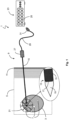
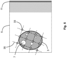
- the organ 3 here has several pathological tissue areas 7 (all of which are marked by a dotted border in the figures), in which an administered photosensitizer or marker substance has accumulated.
- pathological tissue areas 7 all of which are marked by a dotted border in the figures
- an administered photosensitizer or marker substance has accumulated.
- pathological tissue areas 7 due to their small size and/or insufficient contrast, for example, not all pathological tissue areas 7 are visualized and accordingly, ie due to their partial invisibility for the operator, not all of them can be treated individually, ie focally or tissue-specifically.
- All of the visible and invisible pathological tissue areas 7 should now be irradiated with light in order to achieve a corresponding therapeutic effect on all pathological tissue areas 7 . If certain pathological tissue areas 7, for example a tumor, are not irradiated, they remain untreated and can enlarge or otherwise remain or become medically defective.
- the system 1 has a needle-like light applicator 9 which is pierced through the skin 11 of the body 5, ie transcutaneously, into the organ 3.
- the light applicator 9 is as thin as possible in order to damage as little healthy tissue of the body 5 as possible with the puncture, ie to enable a minimally invasive intervention.
- a light-emitting element 17 in the form of an LED is arranged at the distal end 13 of a thin shaft-shaped insertion section 15 of the light applicator 9 .
- a light-transparent and light-scattering applicator tip 19 is arranged on the distal end 13 of the insertion section 15 of the light applicator 9 on the distal side of the LED 17 .
- the light of the LED 17 is emitted as isotropically as possible in a solid angle of more than 3 ⁇ .
- the light emission from the applicator tip 19 is therefore approximately spherical, which is 1 is indicated by a dashed light sphere 21 or in the present sectional view by a dashed circle.
- the size of the light ball 21 as an orientation or measure of the tissue area or tissue volume in which a sufficiently high amount of light arrives with regard to the desired therapeutic effect depends on the Depth of penetration of the light into the tissue of the organ 3 and is therefore organ-specific.
- the system 1 also has a supply unit 23, with which the light applicator 9, with which the LED 17 is operated, is supplied with power.
- the supply unit 23 preferably has a plurality of connections 25 for a plurality of individual light applicators 9, which can be used simultaneously in PDT.
- the light applicator 9 has a grip element 27 at the proximal end of the insertion section 15, with which an operator can grip and position the light applicator 9 manually.
- the light applicator 9 can be connected and supplied with power via a cable 29 with a plug 31 that fits into one of the connections 25 of the supply unit 23 .
- the insertion section 15 of the light applicator 9 preferably has a core and a cladding electrically insulated from the core, so that the core and cladding can function as a forward and return conductor pair to supply the LED 17 with power.
- an extra current conductor can be provided in the insertion section 15 of the light applicator 9 .
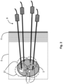
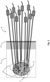
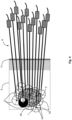
- the penetration depth of the light is relatively small, ie the light spheres 21 are relatively small, so that a relatively large number of light applicators 9 are required in order to completely irradiate the organ 3 .
- the position with regard to correct placement of the light applicators 9 or their applicator tips 19 is compared with that in 1 and 2 correspondingly more complex for the operator, which ultimately means that the probability that certain tissue areas of the organ 3 will not be irradiated and therefore a pathological tissue area 7 will remain untreated (e.g. in 3 centre-left), increases even more.
- the target point lattice structure 35 is adapted to the shape and position of the organ 3 and to the penetration depth of the light in the organ 3 .
- the target point grid structure 35 is therefore organ-specific.
- the distances between the virtual target points 33 are adapted to the organ 3 in such a way that on the one hand the light balls 21 overlap without a gap and the entire organ 3 is irradiated without a gap, but on the other hand this overlapping is preferably only advanced as far as necessary in the sense of a patient-friendly procedure, ie that unnecessarily small distances between the light-emitting applicator tips 19 are avoided, in order thereby to minimize the number of light applicators 9 or light applicator punctures.
- These two conflicting requirements result in a reference point grid structure 35 in which the position and, above all, the distances between the virtual reference points 33 are defined very precisely and have comparatively narrow tolerances.
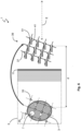
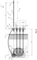
- the 6 and 7 now illustrate the procedure according to the invention for solving the problem described above, ie the precise placement of the light-emitting applicator tips 19 in the virtual and invisible target points 33, which consists of two steps.
- the virtual and invisible reference point grid structure 35 with its virtual and invisible reference points 33 from inside the body 5 is mapped onto a fixation point grid structure 37 outside of the body 5, which is mapped by a real existing and visible placement template 39 with real existing and visible and therefore also targeted and directly controllable by the operator with the light-emitting applicator tips 19 Fixation point recordings 51 is formed.
- This mapping of the target point grid structure 35 onto the fixation point grid structure 37 is a parallel displacement or translation by a defined length d, which is defined by the distance of the organ 3 to the space outside the body where the placement template 39 is to be positioned, parallel to an axis E, the direction of which is defined by the puncture axis of the applicators 9 (see also 7 ).
- This specific form of the mapping carried out here ie the parallel displacement of the reference point grid structure 35 or the reference points 33 with their two characteristic parameters, displacement length d and displacement direction E, should be in the 6 be explicitly illustrated again in a schematic way by the thick arc-shaped arrow pointing to the right.
- Axis E is preferably, but not necessarily, orthogonal to skin 11.
- the actual, therapy-preparing applicator placement then takes place, in that the light-emitting applicator tips 19 are first guided to the actually existing and visible and thus specifically and directly controllable fixation point receptacles 51 of the placement template 39, in order to be placed in or from there in a defined, unambiguous and thus safe manner to be "mapped” or moved to the virtual target points 33 invisible to the operator.
- This second imaging to be carried out as part of the two-stage procedure, i.e.
- the parallel displacement of the light-emitting applicator tips 19 from outside the body 5 into the body 5 is now characterized in accordance with the procedure according to the invention by the fact that it is related to the first, in 6 shown figure, the parallel displacement of the reference point grid structure 35 from inside the body 5 to the outside, is inverse.
- This specific form of the second mapping carried out here ie the parallel displacement with its two characteristic parameters, displacement length d and displacement direction E, should be in the 7 be explicitly illustrated again in a schematic way by the thick arc-shaped arrow pointing to the left.
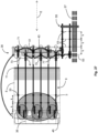
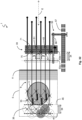
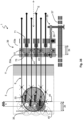
- the placement template 39 is additionally provided with guides 41 in addition to the already mentioned fixation point receptacles 51, which have a defined alignment, namely a parallel alignment to the axis E, whereby only one, namely that defined for the desired inverse parallel translation direction of movement of the light applicators 9 with their applicator tips 19, parallel to the axis E, is permitted or possible, and secondly, in that the light applicators 9 are all provided with at least one fixing point 43, which has a defined distance d from the light-emitting applicator tip 19, viz corresponds exactly to the displacement length d of the reference point lattice structure 35 in the first imaging or parallel displacement, and which can be fixed in or on the fixing point receptacles 51 of the placement template 39, whereby only a single penetration depth, namely the penetration depth defined for the desired inverse parallel displacement, of the associated light-emitting
- the operator therefore only has to bring the light applicators 9 to the fixation point receptacles 51, then guide them through the guides 41 and pierce transcutaneously into the organ 3 until the fixation point 43 is at the grid point of the fixation point grid structure 37, i.e. at the fixation point receptacle 51. Then the applicator tip 19 is also automatically placed at the associated set point 33 .
- the operator has thereby - in contrast to the procedure as based on the 2 and 3 described - no or only a few degrees of freedom and does not require much experience.
- the placement can be carried out quickly with just as many punctures as necessary, but with as few punctures as possible.
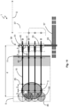
- the PDT can be carried out simultaneously with all placed light applicators 9, which allows a short treatment time. this is in 8 shown. For the sake of clarity, the light balls 21 are not shown there 8 thus shows the situation immediately before or immediately after the irradiation.
- the inventive procedure is therefore based firstly on carrying out two images, namely on the one hand the image of the target points 33 on the fixation point receptacles 51 of the placement template 39 and on the other hand the image of the light-emitting applicator tips 19 starting from the fixation point receptacles 51 back onto the target points 33, with the second image correspondingly characterized in that it is the inverse of the first image, and secondly that it is mechanically and constructively ensured that the second image, which corresponds to the actual applicator placement by the operator, is without alternative, i.e. a movement of the applicators that deviates from the second image 9 or the applicator tips 19 - starting from the fixing points or fixing point receptacles 51 into the body 5 and into the organ 3 - is not possible at all.
- the number of light applicators 9 required increases greatly. For example, doubling the diameter of a spherical organ 3 means that eight times as many light applicators 9 are required. If, on the one hand, the penetration depth of the light is comparatively small and, on the other hand, the extension of the organ 3 along the puncture axis E is comparatively large, then the density of the light applicators 9 in the planes perpendicular to the puncture axis E is correspondingly high and it can happen that the light applicators 9 not enough space next to each other find. This will be at the 7 and 8th Clearly, where the previously described procedure in this respect almost reaches its limits, especially if you also take into account a handy handle with the light applicators 9, which is in the 7 and 8th is not marked at all.
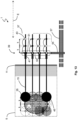
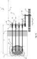
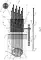
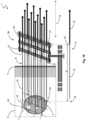
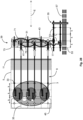
- FIG. 9 and 10 shows how the PDT can be carried out step by step in target point grid areas 45 of the target point grid structure 35 .
- the fixation points 43 of the light applicators 9 are placed or fixed at the grid points or the fixation point receptacles 51 of an associated fixation point grid surface 47 of the fixation point grid structure 37, so that the applicator tips 19 are placed at the associated target points 33 of the target point grid surface 45.
- the PDT is first carried out for the first target point grid area 45, which is preferably the target point grid area 45 lying deepest under the skin, ie furthest distally.
- the light applicators 9 can be retracted proximally by a distance k of the target point grid areas 45 in order to carry out the PDT for the second target point grid area 45 .
- This is carried out step by step for all target point grid areas 45 until the entire volume of the organ 3 has been irradiated with light.
- the advantage of this procedure is that fewer light applicators 9 and fewer punctures are required than with the 8 shown embodiment.
- all light applicators 9 can also be introduced in this way and they do not get in each other's way. However, the duration of the treatment is longer, since the PDT is carried out step by step or one after the other on each target point grid area 45 and not in one step or not simultaneously for the entire organ 3.
- a virtual and invisible reference point grid surface 45 of the virtual and invisible reference point grid structure 35 with its reference points 33 from inside the body 5 is mapped onto a corresponding fixation point grid surface 47 of the fixation point grid structure 37 outside of the body 5, which is represented by a real existing and visible placement template 39 with real existing and visible fixation point recordings 51, which can therefore also be controlled by the operator with the light-emitting applicator tips 19 in a targeted and direct manner.
- This mapping of the reference point grid surface 45 onto the fixed point grid surface 47 is, as in the case of the 6 Explained procedure to a parallel displacement or translation by a defined length d, which is defined by the distance of the organ 3 to the space outside the body 5, where the placement template 39 is to be positioned, parallel to an axis E whose direction through the Puncture axis of the applicators 9 is defined (see also 10 ).
- This specific form of the mapping carried out here ie the parallel displacement of the desired point grid surface 45 with its two characteristic parameters, displacement length d and displacement direction E, should be in the 9 be explicitly illustrated again in a schematic way by the thick arc-shaped arrow pointing to the right.
- the actual, therapy-preparing applicator placement then takes place, in that the light-emitting applicator tips 19 are first guided to the actually existing and visible and thus specifically and directly controllable fixation point recordings 51 of the fixation point grid surface 47 of the placement template 39, in order to move from there in a defined, clearer and thus safer way Way in or to the virtual and for the operator invisible reference points 33 to be "imaged" or moved.
- This second mathematical mapping to be carried out as part of the two-stage procedure, i.e.
- the positioning template 39 is provided with guides 41 in addition to the already mentioned fixing point mounts 51, which have a defined alignment, namely a parallel alignment to the axis E, whereby only a single direction of movement, namely the one defined for the desired inverse parallel displacement, of the light applicators 9 with their applicator tips 19 parallel to the axis E, is permitted or possible, and secondly because the light applicators 9 are all provided with at least one fixing point 43, which has a defined distance d from the light-emitting applicator tip 19, which is precisely the displacement length d of the target point grid surface 45 in the first image or parallel displacement, and which can be fixed in or on the fixing point receptacles 51 of the placement template 39, whereby only a single penetration depth, namely the depth defined for the desired inverse parallel displacement, of the associated light-emitting applicator tip 19 in the Body 5 and approved in the organ 3 or is possible.
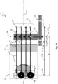
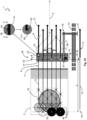
- Figures 11 to 16 show various implementation options for the step-by-step PDT in target point grid areas 45.
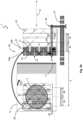
- the light applicators 9 each have several fixing points 43 arranged at a distance k, so that the operator can select the fixing point 43, which is placed at the corresponding grid point of the fixing point grid structure 37 or at the corresponding fixing point receptacle 51 of the placement template 39 in order to determine the target point grid surfaces 45, in which the applicator tip 19 should lie.
- the three-dimensional fixation point grid structure 37 is defined here on the one hand by fixed fixation point recordings 51, which lie on a fixation point recording grid surface 53, and on the other hand by the fixing points 43 of the light applicators 9 arranged at a distance k, with this three-dimensional fixing point grid structure 37 being built up step by step in the procedure shown here and their final shape and size only reached after all fixer points 43 of each light applicator 9 have passed through the respective associated fixation point receptacle 53 of the placement template 39 step by step, which is finally in the state of 13 is reached.
- the fixation point receptacles 51 of the fixation point receptacle grid surface 53 are arranged in or on the guides 41 of the placement template 39 .
- the placement template 39 has a fastening device 55, with which the placement template 39 can be fixed in a position and/or alignment set by the operator relative to a fixed reference surface 57, for example a treatment table.
- the patient's body 5 is also fixed relative to the fixed reference surface 57, for example a treatment table.
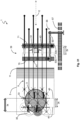
- the light applicators 9 do not each have a plurality of fixing points 43 arranged at a distance k, but the placement template 39 can be displaced as a whole by the distance k in relation to the fixed reference surface 57 .
- the placement template 39 uses the fastening device 55 to define a plurality of fixing points 44 arranged at a distance k in order to be able to move the fixing point receiving grid surface 53 as a whole by the distance k in a defined manner. This has the advantage that the light applicators 9 do not have to be moved individually when changing to the next setpoint grid surface 45, but are moved together in concert. This speeds up and simplifies the treatment process.
- the organ 3 is irradiated with the applicator tips 19 in the second target point grid area 45.
- the organ 3 is then irradiated with the applicator tips 19 in the third and last setpoint grid area 45 .
- the fixation point grid structure37 is no longer shown.
- the positioning template 39 is here a block or other shaped body with a certain thickness along the puncture axis E, through which a multiplicity of guides 41 arranged parallel to one another along the puncture axis E runs.
- Each guide 41 has a fixation point receptacle 51 which forms a lattice point of the fixation point lattice structure 37 .
- the three-dimensional fixation point grid structure thus formed 37 is identical to the organ-specific virtual target point lattice structure 35 for the applicator tips 19 and emerges from it through a parallel displacement or translation by the length d.
- Each light applicator 9 has a thin insertion section 15 and a thicker proximal section, which serves as a gripping element 27 and as a guide in the guides 41 .
- the fixing point 43 is thereby formed as a spherical stop, which is arranged at the proximal end of the insertion section 15 .
- the guides 41 are dimensioned to match the diameter of the insertion section 15 and the thicker proximal section of the light applicators 9 .
- the light applicators 9 are preferably all identical in order to avoid the risk of an incorrect selection of a “wrong” light applicator 9 and, as a result, incorrect positioning of the light-emitting applicator tip 19 in the organ 3.
- the operator has no degrees of freedom, but can only pierce the light applicators 9 in one way until the fixing points 43 engage in the fixing point receptacles 51 .
- the fixing point receptacles 51 have jaw clamps or some other clamping means. This gives the operator haptic feedback on correct placement and prevents the light applicators 9 from slipping in the proximal direction.
- the relative position of the placement template 39 can preferably be determined as follows. The placement template 39 is first placed and fixed with the fastening device 55 on the reference surface 57 very close to the body 5 or to the skin 11 .
- a first light applicator 10 which is to be positioned centrally with respect to a plane perpendicular to the puncture axis E and distally with respect to the puncture axis E itself, is inserted and—controlled with an imaging method (e.g. ultrasound sonography)—pushed forward until its applicator tip 19 has reached the distal area of the organ 3, such as in 17 shown. Then - while maintaining this position of the first light applicator 10 or its applicator tip 19 - the placement template 39 is pulled back axially by means of the fastening device 55 on the reference surface 57, i.e.
- an imaging method e.g. ultrasound sonography
- the fixing point 43 can be fixed in the fixing point receptacle 51, ie in the case shown here it engages in the jaw clamp.
- the positioning template 39 is then fixed in this position on the reference surface 57 by means of the fastening device 55 .
- the defined distance d between the virtual desired point grid structure 35 and fixed point grid structure 37 is produced.
- This process thus completes the first step of the procedure according to the invention, namely the first mapping, i.e. the parallel displacement or translation of the virtual target point grid structure 35 in the organ 3 inside the body 5 into an area outside the body 5, and thus creates the prerequisite for the actual therapy preparation , namely the correct placement of the remaining light applicators 9 or their light-emitting applicator tips 19 in the organ 3.
- the remaining light applicators 9 then only have to be guided through the remaining guides 41 of the positioning template 39 and fixed with their fixing points 43 on the respective fixing point receptacle 51 .
- the degrees of freedom of the operator are minimized, which in turn means that the positions of the remaining light applicators 9 and subsequently the positions of their light-emitting applicator tips 19 are clearly defined after the placement template 39 has been fixed and thus automatically match the target points 33 .
- the placement template 39 consists of a plurality of plates positioned firmly relative to one another that consists of the block 18 substitute. This makes the placement template 39 lighter and unnecessary material for the placement template 39 is saved.
- the plates preferably each have the fixation point receptacles 51 of a fixation point receptacle grid surface 53 .
- the plates are preferably arranged parallel to one another. They can run orthogonally to the puncture axis E or, as in 18 , at an angle to it.
- fixation point recordings 51 again correspond to the grid points of the fixation point grid structure 37, which is identical in terms of shape and size to the organ-specific virtual target point grid structure 35 for the applicator tips 19 and which results from it by a parallel displacement or translation by the length d.
- Figures 19 to 21 show an example of the in Figures 11 to 13
- the principle shown for step-by-step PDT in target point grid areas 45 i.e. here the light applicators 9 and with them the light-emitting applicator tips 19 are moved step-by-step along the puncture axis E via a number of fixing points 43 arranged at a distance k, while the placement template 39 is in an unchanged position via the fastening device 55 in relation to the Reference surface 57 remains fixed.
- the fixing point receptacles 51 are formed here by engagement elements 59 which laterally engage in the guides 41 in a resilient manner.
- the fixing points 43 are correspondingly formed by lateral engagement receptacles 61 in the form of tapers on the light applicator 9 .
- the fixing points 43 are at a distance k along the puncture axis E, which corresponds to the distance k between the target point grid surfaces 45 of the target point grid structure 35 .
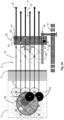
- Figures 22 to 24 show an embodiment for which in Figures 14 to 16 shown principle for the gradual PDT in target point grid areas 45.
- this embodiment integrates the in 8 principle shown, namely that in one irradiation unit all target points are covered from a plurality of target point grid areas 45 at the same time, in the present embodiment specifically from two target point grid areas 45 at the same time.
- This principle of treating several target point grid surfaces 45 at the same time becomes particularly important when the extension of the organ 3 - above all along the puncture axis E - is comparatively large, because this means that the same amount of time or the same number of a significantly larger volume can be treated using sequential irradiation units (in the present examples three irradiation units) (cf 19 with 22 ).
- the placement template 39 has fixing point recordings 51 of two adjacent fixing point recording grid surfaces 53 .
- the placement template 39 can then be displaced by twice the length, namely by 2k, in comparison with the previously described embodiment, in order to carry out the PDT for the following two target point grid areas 45 .
- This procedure ie that in one irradiation unit all target points from a plurality of target point grid areas 45 are covered simultaneously, in comparison with the previously described embodiment ( Figures 19 to 21 ) in the same time, ie with the same number of irradiation units, larger organs 3, ie organs 3 that are more extensive along the puncture axis E, can be treated (cf 21 with 24 ).
- the fixing points 43 and the fixing point receptacles 51 form in the present embodiment a type of bayonet lock, in which a lateral projection 63 on the light applicator 9 can be rotated by rotating the light applicator 9 about the puncture axis E in a corresponding lateral receiving lock 65 in the guide 41 .
- the fastening device 55 of the positioning template 39 has an engagement element 67 which engages in engagement receptacles 69 which are arranged fixedly with respect to the reference surface 57 at a distance of 2k along the puncture axis E.
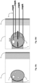
- FIG. 25a,b and 25c,d the two basic variants of the "trigger effect" to be avoided are schematically illustrated, which can occur individually or in combination with transcutaneous PDT.
- Figure 25a shows the normal position and the original shape of the organ 3 in the patient's body 5 without inserted light applicators 9. If the light applicators 9 inserted during the course of the therapy are moved or withdrawn together or at the same time, and is the position of the light applicators 9 If the total static friction force exerted and effective on the organ 3 is greater than the binding forces that act within the surrounding tissue 4 directly connected to the organ 3 and are in turn smaller than the binding forces that are effective within the organ 3 itself, the organ will "fork out".
- Figure 25c shows once again the normal position and original shape of the organ 3 in the patient's body 5 without the light applicators 9 inserted and effective total static friction force is now greater than the binding forces acting within the organ 3 itself, which are also smaller than the binding forces acting within the surrounding tissue 4 directly connected to the organ 3, as in Figure 25d shown, then the organ 3 is "forked” by the light applicators 9 in such a way that the light applicators 9 pull the organ 3 apart or stretch it.
- Figure 25d is shown schematically.
- step-by-step PDT in target point grid areas 45 in which the placement template 39 as a whole is moved step-by-step by defined distances relative to the fixed reference area 57, and the introduced light applicators 9 with their light-emitting applicator tips 19 are moved simultaneously or jointly, as is shown with reference to Figures 11 to 13 explained in schematic form and based on the Figures 22 to 24 shown by way of example in a specific embodiment, this is problematic since it is not clear where the organ 3 is located or how much the organ 3 has been deformed when the light applicators 9 for the PDT are retracted in the next setpoint grid area 45 .
- the two fixation point receiving grid surfaces 53 are shifted by the distance 2k from the distal position to the adjacent, proximal position, which is done by shifting the placement template 39 from the distal engagement receptacle 69 to the directly adjacent, proximal engagement receptacle 69 (in Fig 22 the centrally located engagement receptacle 69), then the applicator tips 19 are also displaced in the proximal direction by the distance 2k.
- the objective of realizing effective and, above all, homogeneous irradiation of the organ 3 on the basis of the original target point grid structure 35 in a simple and convenient manner for the operator by sequentially moving and locking the template 39 in the given intervention receptacles 69 can be achieved under these circumstances ie that the organ 3 is moved and/or stretched in an undesired and, above all, undefined manner by the total static friction force acting on the organ 3 of the light applicators 9 moving together or at the same time, can no longer be achieved.
- the positioning template 39 here has at least two parts, namely a first template part 71, which defines a first subgroup 73 of the guides 41 with fixing point receptacles 51, and a second template part 75, which defines a second subgroup 77 of the guides 41 with fixing point receptacles 51.
- the first template part 71 is guided and displaceable along the puncture axis E relative to the second template part 75 .
- different subgroups of light applicators 9 can be selectively moved or held in concert together by the corresponding subgroups 73, 77 of guides 41 with fixing point receptacles 51.
- Figures 29 to 32 show a further embodiment for avoiding the "fork-up effect" in which the PDT is analogous to the embodiment according to FIG Figures 22 to 24 is carried out in two setpoint grid areas 45 simultaneously.
- this procedure plays an important role when the organ 3 to be treated is larger and, above all, more extensive along the puncture axis E, because within the same time or with the same number of sequential irradiation units (im present case three sequential irradiation units) a larger volume can be treated (compare 29 with 19 ).
- the positioning template 39 here has two parallel plates 71, 75, which form the template parts 71, 75 and are guided along the puncture axis E and can be moved relative to one another.
- the first template part 71 has the fixation point recordings 51 from a first fixation point reception grid surface 53b and the second template part 75 has the fixation point recordings 51 from a second fixation point reception grid surface 53a.
- the placement template 39 in a 29 and 30 shown first relative position, in which the plates 71, 75 lie against one another, the placement template 39 essentially does not differ from that in Figures 22 to 24 shown embodiment and can be used in the same way, provided that no "trigger effect" is to be feared.
- the first template part 71 is initially withdrawn by 2k while the second template part 75 is held in place.
- the second template part 75 can be pulled proximally by 2k while the first template part 71 is held in place.
- the subgroup of light applicators 9, which is fixed in the first template part 71 and is moved with it, is initially covered with tissue of the organ 3 over a shaft length similar to that of the subgroup of light applicators 9, which is fixed in the second template part 75 and later to be moved with that, but initially remains in place according to the procedure described above.
- the difference in length in terms of fabric coverage is only k, resulting in 30 illustrated by the thick, dark gray double arrow in the top left of the figure. Because all the light applicators 9 are also very far into the organ 3, this difference in length is only of secondary importance.
- the sum of the static friction forces exerted on the organ 3 by its subgroup of light applicators 9 during the movement of the first template part 71 is similar in magnitude to the sum of the static friction forces acting in the opposite direction of the subgroup of the stationary light applicators 9 of the second template part 75.
- the sub-group of light applicators 9, which is fixed in the first template part 71 and now remains in place according to the procedure described above, is a length 3k less with tissue of the Organs 3 covers as the subgroup of the light applicators 9, which is fixed in the second template part 75 and is now drawn in the proximal direction, which in 31 illustrated by the thick, dark gray double arrow in the top left of the figure.
- this already greater length difference 3k is of even greater importance.
- the subgroup of the moving light applicators 9 of the second template part 75 exerts a significantly higher total static friction force on the organ 3 than the subgroup of the stationary light applicators 9 of the first template part 71.
- the static friction forces can then be compensated for during the movement or .
- the resulting total static friction force is therefore significantly different from zero, which means that the organ 3 is carried along in the proximal direction by the subgroup of the light applicators 9 of the second template part 75, as already shown in FIG Figure 25b shown schematically, and leads to a changed position in the body 5, as in 32 shown.
- the setpoint grid structure 35 no longer covers the organ 3 in the way originally intended, as was the case at the beginning and, for example, in FIG 29 is shown.
- the treatment can no longer be carried out in the originally planned simple, fast, defined and - with regard to a complete irradiation - safe way.
- a solution to the problem described above is shown in the exemplary embodiment of FIG Figures 33 to 36 explained procedure.
- a characteristic of this procedure is that if the second template part 75 can only be displaced in the proximal direction relative to the first template part 71 until it abuts against the first template part 71, when the second template part 75 rests on the first template part 71, the first subgroup defined by the first template part 71 73 of the fixing point recordings 51 is located distally from the second subgroup 77 of the fixing point recordings 51 defined by the second template part 75 .
- the fixation point receptacles 51 of the second template part 75 are no longer located in the fixation point receptacle grid surface 53a of the second template part 75, as was the case in the previous exemplary embodiment, see for example FIG 29 , but in the fixing point receiving grid area 53b of the first template part 71.
- the fixing point recordings 51 of the first template part 71 are now no longer in the fixing point receiving grid area 53b of the first template part 71, but in the fixing point receiving grid area 53a of the second template part 75, see Figure 33 .
Landscapes
- Health & Medical Sciences (AREA)
- Engineering & Computer Science (AREA)
- Biomedical Technology (AREA)
- Life Sciences & Earth Sciences (AREA)
- Pathology (AREA)
- Radiology & Medical Imaging (AREA)
- Nuclear Medicine, Radiotherapy & Molecular Imaging (AREA)
- Animal Behavior & Ethology (AREA)
- General Health & Medical Sciences (AREA)
- Public Health (AREA)
- Veterinary Medicine (AREA)
- Biophysics (AREA)
- Surgical Instruments (AREA)
- Radiation-Therapy Devices (AREA)
Applications Claiming Priority (1)
| Application Number | Priority Date | Filing Date | Title |
|---|---|---|---|
| DE102021211331.1A DE102021211331A1 (de) | 2021-10-07 | 2021-10-07 | System zur Durchführung einer transkutanen photodynamischen Therapie (PDT) in einem Organ oder Organsegment eines organischen Körpers |
Publications (1)
| Publication Number | Publication Date |
|---|---|
| EP4162979A1 true EP4162979A1 (fr) | 2023-04-12 |
Family
ID=83193248
Family Applications (1)
| Application Number | Title | Priority Date | Filing Date |
|---|---|---|---|
| EP22193842.6A Pending EP4162979A1 (fr) | 2021-10-07 | 2022-09-05 | Système de mise en uvre d'une thérapie photodynamique transcutanée (pdt) dans un organe ou un segment d'organe d'un corps organique |
Country Status (3)
| Country | Link |
|---|---|
| US (1) | US12296186B2 (fr) |
| EP (1) | EP4162979A1 (fr) |
| DE (1) | DE102021211331A1 (fr) |
Families Citing this family (3)
| Publication number | Priority date | Publication date | Assignee | Title |
|---|---|---|---|---|
| DE102021204909A1 (de) * | 2021-05-14 | 2022-11-17 | Richard Wolf Gmbh | Lichtapplikatorsystem mit Vorstichhilfe |
| DE102021211328A1 (de) * | 2021-10-07 | 2023-04-13 | Richard Wolf Gmbh | System zur Durchführung einer transkutanen fotodynamischen Therapie (PDT) in einem Organ oder Organsegment eines organischen Körpers |
| DE102022205706A1 (de) | 2022-06-03 | 2023-12-14 | Richard Wolf Gmbh | System zur Durchführung einer transkutanen photodynamischen Therapie (PDT) in einem Organ oder Organsegment eines organischen Körpers |
Citations (3)
| Publication number | Priority date | Publication date | Assignee | Title |
|---|---|---|---|---|
| US6048359A (en) | 1997-08-25 | 2000-04-11 | Advanced Photodynamic Technologies, Inc. | Spatial orientation and light sources and method of using same for medical diagnosis and photodynamic therapy |
| US20100329524A1 (en) * | 2006-08-15 | 2010-12-30 | Spectracure Ab | System and method for pre-treatment planning of photodynamic light therapy |
| EP3777974A1 (fr) * | 2019-08-14 | 2021-02-17 | Richard Wolf GmbH | Applicateur de lumière |
Family Cites Families (5)
| Publication number | Priority date | Publication date | Assignee | Title |
|---|---|---|---|---|
| US8845630B2 (en) | 2007-06-15 | 2014-09-30 | Syneron Medical Ltd | Devices and methods for percutaneous energy delivery |
| US9403029B2 (en) * | 2007-07-18 | 2016-08-02 | Visualase, Inc. | Systems and methods for thermal therapy |
| US20090156958A1 (en) | 2007-12-12 | 2009-06-18 | Mehta Bankim H | Devices and methods for percutaneous energy delivery |
| KR102548734B1 (ko) * | 2016-12-16 | 2023-06-28 | 나노스펙트라 바이오사이언스 인크 | 장치 및 약물 치료 방법에서의 사용 |
| DE102019129556A1 (de) | 2019-11-01 | 2021-05-06 | Richard Wolf Gmbh | Lichtapplikator |
-
2021
- 2021-10-07 DE DE102021211331.1A patent/DE102021211331A1/de active Pending
-
2022
- 2022-09-05 EP EP22193842.6A patent/EP4162979A1/fr active Pending
- 2022-10-06 US US17/960,919 patent/US12296186B2/en active Active
Patent Citations (3)
| Publication number | Priority date | Publication date | Assignee | Title |
|---|---|---|---|---|
| US6048359A (en) | 1997-08-25 | 2000-04-11 | Advanced Photodynamic Technologies, Inc. | Spatial orientation and light sources and method of using same for medical diagnosis and photodynamic therapy |
| US20100329524A1 (en) * | 2006-08-15 | 2010-12-30 | Spectracure Ab | System and method for pre-treatment planning of photodynamic light therapy |
| EP3777974A1 (fr) * | 2019-08-14 | 2021-02-17 | Richard Wolf GmbH | Applicateur de lumière |
Non-Patent Citations (2)
| Title |
|---|
| FAMULARI GABRIEL ET AL: "A novel 169 Yb-based dynamic-shield intensity modulated brachytherapy delivery system for prostate cancer - fig.S3", MEDICAL PHYSISCS, vol. 47, 30 December 2019 (2019-12-30), pages 859 - 868, XP093025028 * |
| FAMULARI GABRIEL ET AL: "A novel 169 Yb-based dynamic-shield intensity modulated brachytherapy delivery system for prostate cancer", MEDICAL PHYSICS., vol. 47, no. 3, 30 December 2019 (2019-12-30), US, pages 859 - 868, XP093024936, ISSN: 0094-2405, Retrieved from the Internet <URL:https://onlinelibrary.wiley.com/doi/full-xml/10.1002/mp.13959> [retrieved on 20230220], DOI: 10.1002/mp.13959 * |
Also Published As
| Publication number | Publication date |
|---|---|
| DE102021211331A1 (de) | 2023-04-13 |
| US12296186B2 (en) | 2025-05-13 |
| US20230111389A1 (en) | 2023-04-13 |
Similar Documents
| Publication | Publication Date | Title |
|---|---|---|
| EP4162979A1 (fr) | Système de mise en uvre d'une thérapie photodynamique transcutanée (pdt) dans un organe ou un segment d'organe d'un corps organique | |
| EP1477203B1 (fr) | Electrode épicardique | |
| DE69524130T2 (de) | Endoskopisches Nähsystem | |
| DE69714490T2 (de) | Chirurgisches Gerät zur transmyokardialen Revaskularisation | |
| DE69430163T2 (de) | Vorrichtung zum Anbringen und Einstellen einer Verankerungsvorrichtung | |
| EP1148911B1 (fr) | Systeme de portique | |
| DE60318158T2 (de) | Vorrichtung zum Vorschieben eines Funktionselements durch Gewebe | |
| AT393616B (de) | Chirurgisches heftinstrument zur durchfuehrung von intraluminalen anastomosen | |
| DE2841253C3 (de) | Chirurgisches Nähgerät zum Zusammennähen von Organen mit Metallklammern | |
| DE102005041601A1 (de) | Ablationskatheter zum Setzen einer Läsion | |
| EP4162980A1 (fr) | Système de mise en uvre d'une thérapie photodynamique transcutanee (pdt) dans un organe ou un segment d'organe d'un corps organique | |
| EP4051092B1 (fr) | Applicateur de lumière | |
| EP0315730A2 (fr) | Dispositif pour la dilatation et/ou l'ouverture de vaisseaux sanguins | |
| DE102020124443A1 (de) | Vorrichtungen, systeme und verfahren zum transportieren von hilfsmitteln durch einen engen durchgang in einem körper | |
| DE3145439A1 (de) | Apparat zum anlegen von anastomosen an hohlorganen | |
| EP4285987A1 (fr) | Système pour effectuer une thérapie photodynamique transcutanée (pdt) dans un organe ou segment d'organe d'un corps organique | |
| EP1795230B1 (fr) | Dispositif médicale de rayonnement | |
| EP3622908B1 (fr) | Élément d'alignement permettant d'aligner un guide d'aiguille, dispositif d'alignement; dispositif de guidage, dispositif de traitement ainsi que procédé | |
| DE60208491T2 (de) | Vorrichtung zur Implantation einer Reihe von radioaktiven Samen und nicht-radioaktiven Distanzhaltern | |
| EP2111896B1 (fr) | Dispositif pour rayonnement médical | |
| EP4337310B1 (fr) | Système applicateur de lumière avec manchon de protection | |
| AT527810B1 (de) | Applikator zum Anbringen eines Implantats als Fixationsstelle für eine Gefäßprothese | |
| EP4337311B1 (fr) | Système applicateur de lumière avec un accessoire de pré-perçage | |
| EP4496521A1 (fr) | Instrument de guidage médical, ensemble d'instruments médicaux, dispositif médical et procédé médical | |
| DE202016003213U1 (de) | Medizinisches Nahtgerät |
Legal Events
| Date | Code | Title | Description |
|---|---|---|---|
| PUAI | Public reference made under article 153(3) epc to a published international application that has entered the european phase |
Free format text: ORIGINAL CODE: 0009012 |
|
| STAA | Information on the status of an ep patent application or granted ep patent |
Free format text: STATUS: THE APPLICATION HAS BEEN PUBLISHED |
|
| AK | Designated contracting states |
Kind code of ref document: A1 Designated state(s): AL AT BE BG CH CY CZ DE DK EE ES FI FR GB GR HR HU IE IS IT LI LT LU LV MC MK MT NL NO PL PT RO RS SE SI SK SM TR |
|
| STAA | Information on the status of an ep patent application or granted ep patent |
Free format text: STATUS: REQUEST FOR EXAMINATION WAS MADE |
|
| 17P | Request for examination filed |
Effective date: 20230929 |
|
| RBV | Designated contracting states (corrected) |
Designated state(s): AL AT BE BG CH CY CZ DE DK EE ES FI FR GB GR HR HU IE IS IT LI LT LU LV MC MK MT NL NO PL PT RO RS SE SI SK SM TR |
|
| STAA | Information on the status of an ep patent application or granted ep patent |
Free format text: STATUS: EXAMINATION IS IN PROGRESS |
|
| 17Q | First examination report despatched |
Effective date: 20250305 |