EP4163025B1 - Dispositif et procédé de décomposition de matières composites et de leurs mélanges en composants de matières séparés - Google Patents
Dispositif et procédé de décomposition de matières composites et de leurs mélanges en composants de matières séparés Download PDFInfo
- Publication number
- EP4163025B1 EP4163025B1 EP21306396.9A EP21306396A EP4163025B1 EP 4163025 B1 EP4163025 B1 EP 4163025B1 EP 21306396 A EP21306396 A EP 21306396A EP 4163025 B1 EP4163025 B1 EP 4163025B1
- Authority
- EP
- European Patent Office
- Prior art keywords
- material stream
- reactor
- discharged
- rotor
- supplied
- Prior art date
- Legal status (The legal status is an assumption and is not a legal conclusion. Google has not performed a legal analysis and makes no representation as to the accuracy of the status listed.)
- Active
Links
Images


Classifications
-
- B—PERFORMING OPERATIONS; TRANSPORTING
- B09—DISPOSAL OF SOLID WASTE; RECLAMATION OF CONTAMINATED SOIL
- B09B—DISPOSAL OF SOLID WASTE NOT OTHERWISE PROVIDED FOR
- B09B3/00—Destroying solid waste or transforming solid waste into something useful or harmless
- B09B3/30—Destroying solid waste or transforming solid waste into something useful or harmless involving mechanical treatment
- B09B3/35—Shredding, crushing or cutting
-
- B—PERFORMING OPERATIONS; TRANSPORTING
- B02—CRUSHING, PULVERISING, OR DISINTEGRATING; PREPARATORY TREATMENT OF GRAIN FOR MILLING
- B02C—CRUSHING, PULVERISING, OR DISINTEGRATING IN GENERAL; MILLING GRAIN
- B02C13/00—Disintegrating by mills having rotary beater elements ; Hammer mills
- B02C13/14—Disintegrating by mills having rotary beater elements ; Hammer mills with vertical rotor shaft, e.g. combined with sifting devices
- B02C13/18—Disintegrating by mills having rotary beater elements ; Hammer mills with vertical rotor shaft, e.g. combined with sifting devices with beaters rigidly connected to the rotor
- B02C13/1807—Disintegrating by mills having rotary beater elements ; Hammer mills with vertical rotor shaft, e.g. combined with sifting devices with beaters rigidly connected to the rotor the material to be crushed being thrown against an anvil or impact plate
-
- B—PERFORMING OPERATIONS; TRANSPORTING
- B02—CRUSHING, PULVERISING, OR DISINTEGRATING; PREPARATORY TREATMENT OF GRAIN FOR MILLING
- B02C—CRUSHING, PULVERISING, OR DISINTEGRATING IN GENERAL; MILLING GRAIN
- B02C21/00—Disintegrating plant with or without drying of the material
-
- B—PERFORMING OPERATIONS; TRANSPORTING
- B02—CRUSHING, PULVERISING, OR DISINTEGRATING; PREPARATORY TREATMENT OF GRAIN FOR MILLING
- B02C—CRUSHING, PULVERISING, OR DISINTEGRATING IN GENERAL; MILLING GRAIN
- B02C23/00—Auxiliary methods or auxiliary devices or accessories specially adapted for crushing or disintegrating not provided for in preceding groups or not specially adapted to apparatus covered by a single preceding group
- B02C23/02—Feeding devices
-
- B—PERFORMING OPERATIONS; TRANSPORTING
- B02—CRUSHING, PULVERISING, OR DISINTEGRATING; PREPARATORY TREATMENT OF GRAIN FOR MILLING
- B02C—CRUSHING, PULVERISING, OR DISINTEGRATING IN GENERAL; MILLING GRAIN
- B02C23/00—Auxiliary methods or auxiliary devices or accessories specially adapted for crushing or disintegrating not provided for in preceding groups or not specially adapted to apparatus covered by a single preceding group
- B02C23/08—Separating or sorting of material, associated with crushing or disintegrating
-
- B—PERFORMING OPERATIONS; TRANSPORTING
- B03—SEPARATION OF SOLID MATERIALS USING LIQUIDS OR USING PNEUMATIC TABLES OR JIGS; MAGNETIC OR ELECTROSTATIC SEPARATION OF SOLID MATERIALS FROM SOLID MATERIALS OR FLUIDS; SEPARATION BY HIGH-VOLTAGE ELECTRIC FIELDS
- B03B—SEPARATING SOLID MATERIALS USING LIQUIDS OR USING PNEUMATIC TABLES OR JIGS
- B03B9/00—General arrangement of separating plant, e.g. flow sheets
- B03B9/06—General arrangement of separating plant, e.g. flow sheets specially adapted for refuse
- B03B9/061—General arrangement of separating plant, e.g. flow sheets specially adapted for refuse the refuse being industrial
-
- B—PERFORMING OPERATIONS; TRANSPORTING
- B09—DISPOSAL OF SOLID WASTE; RECLAMATION OF CONTAMINATED SOIL
- B09B—DISPOSAL OF SOLID WASTE NOT OTHERWISE PROVIDED FOR
- B09B5/00—Operations not covered by a single other subclass or by a single other group in this subclass
-
- B—PERFORMING OPERATIONS; TRANSPORTING
- B02—CRUSHING, PULVERISING, OR DISINTEGRATING; PREPARATORY TREATMENT OF GRAIN FOR MILLING
- B02C—CRUSHING, PULVERISING, OR DISINTEGRATING IN GENERAL; MILLING GRAIN
- B02C13/00—Disintegrating by mills having rotary beater elements ; Hammer mills
- B02C13/26—Details
- B02C13/286—Feeding or discharge
- B02C2013/28618—Feeding means
-
- B—PERFORMING OPERATIONS; TRANSPORTING
- B09—DISPOSAL OF SOLID WASTE; RECLAMATION OF CONTAMINATED SOIL
- B09B—DISPOSAL OF SOLID WASTE NOT OTHERWISE PROVIDED FOR
- B09B2101/00—Type of solid waste
- B09B2101/15—Electronic waste
-
- B—PERFORMING OPERATIONS; TRANSPORTING
- B09—DISPOSAL OF SOLID WASTE; RECLAMATION OF CONTAMINATED SOIL
- B09B—DISPOSAL OF SOLID WASTE NOT OTHERWISE PROVIDED FOR
- B09B2101/00—Type of solid waste
- B09B2101/15—Electronic waste
- B09B2101/17—Printed circuit boards [PCB]
Definitions
- the present invention relates to both a device and a method for breaking down composite materials and mixtures into individual material components.
- the present invention relates to a device such as that known from WO2017/036 534 A1 This corresponds to a device for breaking down a material flow to be supplied from composite materials and form-fitting structures containing composite materials, as well as their mixtures, into individual fractions of the composite materials.
- Such devices and methods are used to break down composite materials and form-fitting structures containing composite materials, as well as their mixtures, by means of tribomechanical and mechanochemical treatment, whereby a material flow consisting of the composite materials is deformed in a decomposing manner inside a reactor, selectively utilizing physical differences between individual particles in the material flow.
- the decomposition takes place through shear forces between the layers, along the phase boundaries of regions where different composite materials meet.
- Some of these composite materials are positively bonded to other composite materials and are therefore difficult to separate.
- Electronic waste in particular represents a very complex type of waste where it is difficult to break down the individual components of the composite material.
- Fig. 2 Other typical wastes that are difficult to recycle are packaging composites made of PE and aluminium as a three-layer laminate, as in Fig. 2 shown schematically.
- the aluminum serves as a barrier layer against light and is used to protect a product wrapped in this laminate against diffusion.
- the aluminum layer is usually located between two layers of plastic, or is laminated on both sides.
- the aluminum layer is between 6 and 80 ⁇ m, depending on the application.
- FIG. 3 schematic of a printed circuit on a circuit board.
- Such circuit boards consist of up to 50 layers of copper and glass fiber epoxy resins (FR4), which serve as electrical conductors (copper) or insulators (glass fiber epoxy). These layers of copper are between 17 and 34 ⁇ m thick. The thickness of the glass fiber epoxy resin layer is > 50 ⁇ m.
- the contact points can be coated with precious metals, especially gold.
- the layer thickness is only a few ⁇ m.
- Fig. 4 shows a sandwich panel, such as that used as cladding in facade construction or vehicle construction, among other things.
- the material is durable and light.
- the layer thickness of the metal, e.g. aluminum, which is on the outside, is between 100 - 300 ⁇ m, that of the plastic core material is approx. 2 - 4 mm.
- packaging composites such as tube laminates
- the materials that are currently processed using inefficient thermal or wet-chemical processes are usually of inferior quality and cause considerable environmental pollution through harmful residues and a relatively high emission of environmentally harmful gases, sludge, waste water and slag.
- the aim of the present invention is therefore to improve the device known from the prior art in such a way that a more efficient and environmentally friendly Separation of composite materials and mixtures of materials is made possible, whereby the service life of such a device is increased and measures are provided with which the most uniform and reliable breakdown of the composite materials to be separated in such a device can be achieved over the entire service life of such a device, despite wear and tear caused by running time, and this for the widest possible range of composite materials with different compositions.
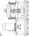
- FIG. 7 A preferred embodiment of a device according to the invention (reactor 1) for separating composite materials and mixtures is shown in Fig. 7 shown.
- the known device shown comprises the one in Fig. 7
- the preferred embodiment of a device according to the invention (reactor 1) shown has a drive unit 4 for driving a rotor 3, which is connected to a bearing/shaft unit, which preferably has an axis of rotation aligned substantially parallel to the earth's gravity.
- the rotating rotor 3 is surrounded by a stationary stator 2 , which in turn is installed in an annular space 10 ( Fig. 9 ) pointing stator tools 7 ( Fig. 9 ) .
- a rotor can also enclose a stator.
- the rotor 3 and the stator 2 are preferably formed essentially cylindrically in the interior of the reactor 1. Depending on the type and composition of the However, depending on the material flow, shapes other than cylindrical ones can also be used for the rotor 3 and the stator 2 .
- the known device (reactor 1) shown in FIG. 1 comprises a material inlet in the form of a simple hopper 5b through which the material flow to be fed to the reactor 1 falls into the interior of the reactor 1.
- a material inlet in the form of a simple hopper 5b through which the material flow to be fed to the reactor 1 falls into the interior of the reactor 1.
- the material to be separated is fed from above the rotor 3 and the stator 2, it reaches the Fig. 8 shown known device uncontrolled into the ring area 10 ( Fig. 9 ), where it is crushed between rotor tools 6 and stator tools 7 and from where it then reaches a material outlet 9 below the rotor 3 and the stator 2 .
- the material inlet is designed in the form of an injector mixer 5a .
- This enables a metered supply of pretreated material in the material flow to be supplied, in particular broken material, into the interior of the reactor 1.
- the injector mixer 5a enables a variable metering of a working fluid, which can be mixed into the material flow to be broken down in the injector mixer 5a under conditions that change over time.
- a curved disk 8 is arranged between the injector mixer 5a on the one hand and the rotor 3 and stator 2 on the other hand in the interior of the reactor 1 in order to direct a stream of composite material to be broken down, which is to be fed to the injector mixer 5a , into the engagement area in the annular space 10 ( Fig. 9 ) between the rotor tools 6 and the stator tools 7 .
- the disk 8 is concavely curved towards a material flow fed from above into the interior of the reactor 1 by the injector mixer 5a . This ensures that fragments of the material flow fed into the interior of the reactor 1 by the injector mixer 5a and to be further broken down there are directed on the surface of the curved disk 8 in a targeted manner into the ring-shaped engagement area (ring area 10) between the rotor tools 6 and the stator tools 7.
- the curved disk 8 thus enables a targeted alignment of the material flow to be broken down inside the reactor 1 to the area where the rotor tools 6 and the stator tools 7 carry out their desired mechanical comminution work on the supplied fragments can unfold directly and without detours in the material flow to be broken down. This increases the efficiency with which the supplied material flow is broken down. Furthermore, unnecessary wear on parts in the interior of reactor 1, which are exposed to a chaotic material flow in the state of the art, is prevented.
- the curved disk 8 inside the reactor 1 is adjustable in the direction of the axis of rotation of the rotor 3. This allows the distance of the curved disk 8 to the injector mixer 5a as well as to the rotor 3 and stator 2 to be optimally adjusted in the vertical direction. This allows the targeted deflection of the material flow introduced into the interior of the reactor 1 by the injector mixer 5a into the engagement area between the rotor tools 6 and the stator tools 7 to be further optimized. Such an adjustment of the distance between the curved disk 8 and the injector mixer 5a or the rotor 3 and the stator 2 can also be carried out in response to any blunting of the rotor tools 6 and stator tools 7 that may occur over time.
- the material flow of broken material made of composite materials (in particular electronic scrap components) which is then to be fed to the injector mixer 5a is pre-crushed by means of a novel two- or three-axis plate crusher, as shown in Fig 5
- this new plate crusher works in two or three directions (axes).
- FIG. 5 The embodiment shown shows a two-axis plate crusher.
- Such a new type of plate crusher causes the material to be broken down into individual components by applying alternating pressure from essentially perpendicular directions to the material to be broken down. This allows a selection of certain individual components before the material flow is actually introduced into the interior of the reactor 1 of the device according to the invention (reactor 1) and, if necessary, enables a pre-separation of the resulting broken components before entering the interior of the reactor 1.
- further means for pre-sorting fragments from the material flow to be fed into the injector mixer 5a in the form of lifting magnets, induction separators and/or multi-sensor separators in particular can be connected between the plate breaker and the injector mixer 5a .
- further means for comminution can be connected between the lifting magnets, induction separators and/or multi-sensor separators on the one hand and the injector mixer 5a on the other.
- These further means for comminution can in particular be shredders, hammer mills and/or granulators which are designed to crush further fragments from the material flow to be fed to the reactor 1 to a size of ⁇ 15 mm and to mix them homogeneously.
- the material stream to be digested is fed to the reactor 1 according to the invention ( Fig. 7 ) with the addition of a gas-liquid mixture (fluid) in the injector mixer 5a for the actual decomposition in the reactor 1 .
- the above-mentioned liquids are fed to the injector mixer 5a under atmospheric pressure and the above-mentioned gases at 500 - 800 kPa with the addition of the solids of the material flow to be broken down.
- the density of the fluid can be significantly influenced by an increased liquid or gas content. The heat energy generated in the process by friction is efficiently dissipated, aided by the liquid content.
- An increased density of the fluid leads to a longer residence time of the solids (composite material to be broken down in the material flow to be fed in) in the annular space 10 inside the reactor 1.
- an increased proportion of liquid leads to electrostatic potential equalization between the particles in the material flow, which prevents the particles from becoming electrostatically charged.
- a further separation of the digested components can optionally be carried out on water separation tables, hydrocyclones and flotation or sedimentation tanks or in filters.
- the mixture discharged from an optionally connected cyclone or filter in the material flow to be discharged from the interior of the reactor 1 can be wetted with water through an optional venturi nozzle immediately after leaving the interior of the reactor 1.
- process steps 1 and 2 are generally not required. Accordingly, in this case the process preferably begins with the comminution in process step 3).
- process step 3 If the input material to be treated consists of a mixture with a size of ⁇ 15 mm, process step 3) is also not required, since in this case the material can be fed directly into the reactor.
- Fig. 6 shows a schematic overview of the individual stations or components that occur in an inventive device and in an inventive method.
- the physical differences between the materials in the composite material are used to break down the composite material. These physical differences naturally occur at boundary layers, i.e. where a single material is separated from another neighboring material.
- the differences between the physical properties of the individual materials, such as density, elasticity, ductility and vibration absorption, are supported by the addition of additives, particularly water and gas, and preferably also conditioned ambient air.
- additives particularly water and gas, and preferably also conditioned ambient air.
- the heat generated during the process is dissipated by utilizing the liquid or water content in the fluid.
- the mechanical impact on the composite material leads to layer-by-layer delamination of the materials through deformation, which also varies due to the different recovery behavior of the composite materials.
- the gas-liquid mixture (fluid) that is fed into the device in the injector mixer 5a promotes the dissolution of the elastic components, such as plastics, rubber, etc., through increased absorption of the resulting vibrations.
- the supply of the material to be processed via an injector mixer 5a, such as a venturi mixer, in which a gas-liquid mixture is mixed with the solid to be processed (composite material particles in the material flow to be supplied).
- the fluid can preferably consist of air and water, or in an application where inerting is required, nitrogen or argon can also be supplied. It has also proven It has been shown that a mixture, e.g. lime and wood flour, can be added to absorb oils or lithium by adding solid auxiliary materials. This prevents oxidation and also enables the mixture to be discharged in a solid form.
- the mixture is fed directly to the annular space 10 ( Fig. 9 ) without colliding with the stator 2 in front of the annular space 10. Entry into the annular space 10, where the material is broken down, can thus be controlled under constant parameters. In addition, wear is significantly reduced, particularly in front of the entry zone of the material into the annular space 10. As a further effect, there is a higher throughput in the device, since there are no more losses due to uncontrolled feeding of the material.
- a device (Reactor 1) is required, as in Fig. 7 and which is continuously filled with a mixture of gas, liquid and the composite material to be treated. This material flow to be fed in is mixed or preconditioned shortly before reactor 1 .
- this mixture should preferably be supplied in a ratio of the following volume units or ratios: Solid (composite material) 2 - 5 volume units to 1.2 - 1.5 volume units of liquid (preferably water) and to 5000 - 12000 volume units of gas (preferably conditioned ambient air).
- reactor 1 which consists of a rotating part (rotor 3) and a fixed part (stator 2) . It has been shown that the arrangement of the axes (horizontal or vertical) is not of decisive importance for the actual digestion process of the material. For optimal feeding, however, it has proven to be practical to feed the material-gas-liquid mixture into a vertically arranged device (reactor) from above.
- the material to be treated (input) is exposed to an enormous particle acceleration, whereby mechanochemical (i.e. generated by the action of the fluid or the components contained in the fluid) and tribomechanical (i.e. generated by the high-frequency, mutual inverse thrusts described below) effects come into play, which subsequently lead to the breakdown or detachment of the individual layers.
- mechanochemical i.e. generated by the action of the fluid or the components contained in the fluid
- tribomechanical i.e. generated by the high-frequency, mutual inverse thrusts described below
- This process of particle acceleration is repeated at high frequency, whereby a thrust is created between the layers along the phase boundaries, which continues in all directions (axes) (thrust - thrust reversal - thrust - ).
- This particle acceleration and these high-frequency, mutual inverse thrusts create shear forces between the layers, which continue in different directions depending on the material.
- a reactor 1 contains a vertically arranged rotating part (rotor) 3, which can be driven up to a peripheral speed of up to 300 m/s by the drive 4.
- the mixture of solid (composite materials) and fluid, preconditioned in the injector mixer 5a is exposed to tribomechanical and mechanochemical conditions between rotor tools 6 and stator tools 7 of different characteristics, in which the composite material breaks down or delaminates.
- the adjustable curved disk 8 accelerates and deflects the mixture in a targeted manner in the Engagement area (annular space 10) between the rotor 3 and the stator 2. After digestion, the mixture is removed from the reactor 1 and fed to the material discharge system 9 .
- the residence time in reactor 1 can be influenced by the peripheral speed of rotor 3 on the one hand and by increasing the fluid content and its composition on the other.
- stator 2 and rotor 3 results in materials such as metals deforming and sphericalizing due to their ductility, whereas materials that are elastic, such as plastics or rubber, hardly change as they absorb the majority of the thrusts, vibrations and shock waves.
- Mineral materials are pulverized due to their brittleness. After the process, the mixture has different, material-specific particle size distributions.
- Brittle components become fine particles, metals become sphere-like deformed layers and elastic components become flake or chip structures.
- the total range of the particle size distribution is between a few micrometers up to the size of the input, hence the feed size of typically 15 mm.
- the materials are different in this range, enriched in normal distributions.
- Additional separator stations (particularly water separation tables) optionally connected downstream of the reactor outlet make it possible to produce a large number of individual fractions in one step.
- the density and buoyancy behavior of the materials are used.
- a crushing process such as that used in WO 2006/117 06 5 A1 described is not the aim of the present invention.
- the digested materials (layers) should not be crushed.
- disintegration is not carried out by means of pulverization, crushing, or acceleration caused by turbulence or the like.
- the disintegration takes place through mechanochemical and tribomechanical effects, which are caused by the mixture of gas with water (fluid) and the input material (composite material) by the impact on the rotor and stator elements.
- working gases and/or working fluids which act on the materials to be broken down and react chemically with them can optionally be added.
- a decisive advantage of the present invention is precisely that the device according to the invention can achieve sufficient efficiency for a large number of composite materials to be digested by purely physical processing steps alone, only with the addition of water and conditioned ambient air, so that a complex and costly provision of special chemicals (and their subsequent, also very complex and costly disposal) can in principle be completely dispensed with.
Landscapes
- Engineering & Computer Science (AREA)
- Food Science & Technology (AREA)
- Environmental & Geological Engineering (AREA)
- Disintegrating Or Milling (AREA)
Claims (15)
- Dispositif de traitement d'un flux de matériaux à introduire constitué de matériaux composites et de structures assemblées par complémentarité de forme lesquelles contiennent des matériaux composites et de leurs mélanges, visant à obtenir des fractions séparées de matériaux composites, ledit dispositif comprenant :un rotor (3) et un stator (2) à l'intérieur d'un réacteur (1), lesquels sont montés rotatifs l'un par rapport à l'autre et lesquels définissent un espace annulaire (10) entre eux dans lequel le flux de matériaux à introduire peut subir un traitement mécanique par l'interaction d'outils de rotor et/ou de stator (6, 7) montés sur le rotor (3) et le stator (2), respectivement,une unité d'entraînement (4) permettant de entraîner le rotor (3),une entrée de matériaux (5) permettant d'introduire le flux de matériaux à introduire dans l'intérieur du réacteur (1),une sortie de matériaux (9) destinée à évacuer un flux de matériaux qui a été mécaniquement traité entre le rotor (3) et le stator (2) et qui est à évacuer de l'intérieur du réacteur (1),caractérisé en ce queladite entrée de matériaux vers l'intérieur du réacteur (1) est réalisée sous forme d'un injecteur-mélangeur (5a) dans lequel le flux de matériaux à introduire peut recevoir un fluide et y être mélangé,un disque bombé (8) qui est monté entre, d'une part, l'injecteur-mélangeur (5a) et, d'autre part, le rotor (3) et le stator (2) à l'intérieur du réacteur (1), pour ainsi dévier, de manière ciblée, le flux de matériaux à introduire à travers l'injecteur-mélangeur (5a) de manière à ce qu'il atteigne la zone annulaire (10) entre le rotor (3) et le stator (2).
- Dispositif selon la revendication 1, la distance entre le disque bombé (8) et l'injecteur-mélangeur (5a) pouvant être réglée.
- Dispositif selon l'une des revendications précédentes, un concasseur à plaques étant disposé en amont de l'injecteur-mélangeur (5a) dans le flux de matériaux à introduire, ledit concasseur à plaquer étant pourvu de deux ou de trois paires de plaques, chacune des paires de plaques comportant une plaque fixe et une plaque pouvant être déplacée selon une direction qui y est sensiblement verticale, pour ainsi concasser le flux de matériaux à faire passer entre lesdites plaques.
- Dispositif selon l'une des revendications précédentes, des aimants suspendus, des séparateurs à induction et/ou des séparateurs à capteurs multiples étant disposés en amont de l'injecteur-mélangeur (5a) dans le flux de matériaux à introduire.
- Dispositif selon l'une des revendications précédentes, des déchiqueteurs, des broyeurs à marteaux et/ou des organes de granulation étant disposés en amont de l'injecteur-mélangeur (5a) dans le flux de matériaux à introduire, pour ainsi broyer les particules et en faire en mélange homogène.
- Dispositif selon l'une des revendications précédentes, un cyclone ou un mélangeur à effet venturi étant disposé en aval de la sortie de matériaux (9) du réacteur (1) afin d'y mélanger le flux de matériaux à évacuer avec le flux d'un gaz de travail, pour ainsi effectuer une séparation des particules au sein du flux de matériaux à évacuer en une ou plusieurs fractions, en exploitant les mobilités différentes des particules, telles qu'elles résultent des différences en ce qui concerne leur densité et leurs tailles de particule, au sein du flux de matériaux à évacuer, par rapport audit gaz de travail.
- Dispositif selon l'une des revendications précédentes, au moins un bassin de flottation et/ou au moins un hydrocyclone étant disposé(s) en aval de la sortie de matériaux (9) dans le flux de matériaux à évacuer, l'au moins un bassin de flottation et/ou l'au moins un hydrocyclone étant réalisé(s) de manière à séparer des particules, contenues dans le flux de matériaux à évacuer, de l'intérieur du réacteur (1) sous forme de fractions, lesdites particules ayant des densités inférieures à la densité prédéfinie de fluides de travail qui devront y être mélangés.
- Dispositif selon l'une des revendications précédentes, au moins une table de séparation à l'eau, susceptible d'être mise en vibration et pourvue d'une surface de travail inclinable, étant disposée en aval de la sortie de matériaux dans le flux de matériaux à évacuer, l'au moins une table de séparation à l'eau étant réalisée de manière à pouvoir effectuer une séparation des particules, contenues dans le flux de matériaux à évacuer, en une ou plusieurs fractions en exploitant les mobilités différentes des particules, telles qu'elles résultent des différences en ce qui concerne leur densité et leurs tailles de particule, au sein du flux de matériaux à évacuer.
- Dispositif selon l'une des revendications précédentes, un organe de séchage étant disposé, en aval de la sortie de matériaux (9) du réacteur (1), dans le flux de matériaux à évacuer.
- Dispositif selon l'une des revendications précédentes, une soufflerie étant disposée dans le flux de matériaux à évacuer, afin de retirer le flux de matériaux du réacteur (1) par action pneumatique.
- Procédé de traitement d'un flux de matériaux entrant comportant des matériaux composites ainsi que des structures assemblées par complémentarité de forme lesquelles contiennent des matériaux composites ainsi que leurs mélanges, visant à obtenir les différents matériaux dont il est composé, mis en œuvre dans un dispositif selon l'une des revendications précédentes, le flux de matériaux entrant étant mélangé, dans l'injecteur-mélangeur (5a) dudit dispositif, avec un fluide vecteur (mélange liquide - gaz).
- Procédé selon la revendication 11, le traitement du flux de matériaux entrant étant effectué en appliquant les paramètres suivants : matières solides issues de matériaux composites 2 à 5 unités volumiques pour 1,2 à 1,5 unités volumiques de liquide, s'agissant préférentiellement d'eau, et pour 5000 à 12000 unités volumiques de gaz, s'agissant préférentiellement d'air ambiant conditionné.
- Procédé selon la revendication 11, ledit gaz étant de l'air ambiant qui a été dépoussiéré et dont la température et l'humidité ont été réglées de manière contrôlée.
- Procédé selon l'une des revendications de procédé précédentes, l'évacuation de la chaleur étant réalisée, pendant le traitement du flux de matériaux à introduire à l'intérieur du réacteur (1), au moyen dudit fluide vecteur.
- Procédé selon l'une des revendications de procédé précédentes,les particules au sein du flux de matériaux à évacuer de la sortie de matériaux lesquelles présentent une densité supérieure à la densité d'un liquide de travail à introduire dans le flux de matériaux étant mises en flottation dans ce liquide de travail pour ainsi former une suspension et acheminées vers des tables de séparation à l'eau, où des fractions des morceaux sont précipitées à partir de la suspension sous forme de différents sédiments au moyen desdites tables de séparation à l'eau, et/ouune séparation en matières plastiques, aluminium et d'autres métaux légers, cuivre, alliages des cuivre, métaux précieux et/ou métaux de terres rares enrichis, étant réalisée au moyen d'une séparation basée sur la combinaison entre les différentes densités des particules dans le flux de matériaux à évacuer et la mise en vibration d'un plan incliné d'une table de séparation à l'eau laquelle exploite les différentes mobilités de chacune des particules faisant partie du flux de matériaux à séparer, et/oule mélange étant acheminé par action pneumatique vers un cyclone à gaz et/ou un filtre, en retirant du gaz, notamment de l'air, et en ajoutant du liquide, notamment de l'eau, pour ainsi former une suspension, ladite suspension étant traitée dans un bassin de flottation et/ou sur une table de séparation à l'eau et/ou un hydrocyclone, afin de séparer les différentes fraction contenues dans ladite suspension.
Priority Applications (1)
| Application Number | Priority Date | Filing Date | Title |
|---|---|---|---|
| EP21306396.9A EP4163025B1 (fr) | 2021-10-05 | 2021-10-05 | Dispositif et procédé de décomposition de matières composites et de leurs mélanges en composants de matières séparés |
Applications Claiming Priority (1)
| Application Number | Priority Date | Filing Date | Title |
|---|---|---|---|
| EP21306396.9A EP4163025B1 (fr) | 2021-10-05 | 2021-10-05 | Dispositif et procédé de décomposition de matières composites et de leurs mélanges en composants de matières séparés |
Publications (3)
| Publication Number | Publication Date |
|---|---|
| EP4163025A1 EP4163025A1 (fr) | 2023-04-12 |
| EP4163025C0 EP4163025C0 (fr) | 2024-11-06 |
| EP4163025B1 true EP4163025B1 (fr) | 2024-11-06 |
Family
ID=78516725
Family Applications (1)
| Application Number | Title | Priority Date | Filing Date |
|---|---|---|---|
| EP21306396.9A Active EP4163025B1 (fr) | 2021-10-05 | 2021-10-05 | Dispositif et procédé de décomposition de matières composites et de leurs mélanges en composants de matières séparés |
Country Status (1)
| Country | Link |
|---|---|
| EP (1) | EP4163025B1 (fr) |
Family Cites Families (4)
| Publication number | Priority date | Publication date | Assignee | Title |
|---|---|---|---|---|
| WO1995025595A1 (fr) * | 1994-03-23 | 1995-09-28 | Rudolf Engel | Procede et dispositif pour le traitement d'elements composites |
| DE102005020441A1 (de) | 2005-04-29 | 2006-11-02 | Silver Cay Worldwide Corp. | Vorrichtung und Verfahren zum Behandeln von Verbundelementen |
| MX2013006097A (es) * | 2010-12-01 | 2013-10-01 | Swiss Redux Engineering Ag | Dispositivo para separar materiales compuestos. |
| US11192118B2 (en) | 2015-09-03 | 2021-12-07 | Deniz Graf | Method and device for separating composite materials and mixtures, in particular solid-material mixtures and slags |
-
2021
- 2021-10-05 EP EP21306396.9A patent/EP4163025B1/fr active Active
Also Published As
| Publication number | Publication date |
|---|---|
| EP4163025C0 (fr) | 2024-11-06 |
| EP4163025A1 (fr) | 2023-04-12 |
Similar Documents
| Publication | Publication Date | Title |
|---|---|---|
| DE69223746T2 (de) | Verfahren und Vorrichtung zum Pulverisieren und zur Trennung | |
| DE69816070T2 (de) | Verfahren zur Behandlung von Schredderstaub | |
| DE60300809T2 (de) | Vorrichtung zur Wiedergewinnung von Gipskartonplatten | |
| DE102010046685B4 (de) | Vorrichtung und Verfahren zum Aufbereiten von Rotorblättern von Windkraftanlagen | |
| DE102011086298B4 (de) | Vorrichtung und Verfahren zur selektiven Trennung von Polyurethanschaum und Fasern aus Automobilschredderrückstand | |
| EP2268406B1 (fr) | Procédé et installation pour le traitement de déchets à teneur élevée en matières plastiques | |
| WO2000053324A1 (fr) | Procede et dispositif pour valoriser des dechets de broyeur ou d'autres matieres composites similaires et utilisation d'un broyeur a percussion rotorique | |
| EP1372860B1 (fr) | Installation et procede de traitement de minerais metalliferes | |
| DE102007029498A1 (de) | Verfahren, Anlage und Vorrichtungen zur Aufbereitung kunststoffhaltiger Abfälle | |
| EP1501634A2 (fr) | Procede et dispositif pour le traitement de materiaux, de materiaux composites et de leurs composes | |
| EP4169619B1 (fr) | Procédé et dispositif de production de modules photovoltaïques | |
| DE19726105A1 (de) | Verfahren und Anlage zur Aufbereitung von Elektronik-Schrott und zur Anreicherung verwertbarer, insbesondere Edelmetalle enthaltender Bestandteile | |
| EP0751831B1 (fr) | Procede et dispositif pour le traitement d'elements composites | |
| WO2010072276A1 (fr) | Procédé et dispositif pour désagréger de la matière minérale à broyer | |
| DE19519516C2 (de) | Verfahren und Vorrichtung zur Aufbereitung von Faserbestandteile und Fremdbestandteile enthaltenden Faserstoffen, insbesondere von Alt-Mineralwolle | |
| EP4163025B1 (fr) | Dispositif et procédé de décomposition de matières composites et de leurs mélanges en composants de matières séparés | |
| EP3610958B1 (fr) | Procédé de séparation des matériaux composites et des mélanges, en particulier des mélanges de solides et des scories | |
| EP0330046B1 (fr) | Procédé de récupération de matières plastiques à partir de déchets métaux/plastiques | |
| EP0125435A2 (fr) | Procédé et installation de préparation de matières métalliques enrobées et d'obtention de particules métallifères sphéroidales | |
| EP3895806A1 (fr) | Dispositif et procédé de broyage de matières solides | |
| WO2016124618A1 (fr) | Dispositif de broyage permettant la récupération de substances secondaires présentes dans un matériau éliminé, ainsi que procédé de commande dudit dispositif | |
| EP0623390A1 (fr) | Procédé et installation pour le traitement mécanique de mélanges de déchets | |
| EP3411152B1 (fr) | Procédé de déchiquetage de matériaux solides et dispositif permettant la mise en oeuvre dudit procédé | |
| DD231578A1 (de) | Verfahren zur aufbereitung von metallhaltigen industrieabfaellen, insbesondere leiterplatten | |
| CN121219121A (zh) | 用于将复合材料及其混合物分解成单独材料组分的装置和方法 |
Legal Events
| Date | Code | Title | Description |
|---|---|---|---|
| PUAI | Public reference made under article 153(3) epc to a published international application that has entered the european phase |
Free format text: ORIGINAL CODE: 0009012 |
|
| STAA | Information on the status of an ep patent application or granted ep patent |
Free format text: STATUS: THE APPLICATION HAS BEEN PUBLISHED |
|
| AK | Designated contracting states |
Kind code of ref document: A1 Designated state(s): AL AT BE BG CH CY CZ DE DK EE ES FI FR GB GR HR HU IE IS IT LI LT LU LV MC MK MT NL NO PL PT RO RS SE SI SK SM TR |
|
| STAA | Information on the status of an ep patent application or granted ep patent |
Free format text: STATUS: REQUEST FOR EXAMINATION WAS MADE |
|
| 17P | Request for examination filed |
Effective date: 20231010 |
|
| RBV | Designated contracting states (corrected) |
Designated state(s): AL AT BE BG CH CY CZ DE DK EE ES FI FR GB GR HR HU IE IS IT LI LT LU LV MC MK MT NL NO PL PT RO RS SE SI SK SM TR |
|
| GRAP | Despatch of communication of intention to grant a patent |
Free format text: ORIGINAL CODE: EPIDOSNIGR1 |
|
| STAA | Information on the status of an ep patent application or granted ep patent |
Free format text: STATUS: GRANT OF PATENT IS INTENDED |
|
| INTG | Intention to grant announced |
Effective date: 20240517 |
|
| GRAS | Grant fee paid |
Free format text: ORIGINAL CODE: EPIDOSNIGR3 |
|
| GRAA | (expected) grant |
Free format text: ORIGINAL CODE: 0009210 |
|
| STAA | Information on the status of an ep patent application or granted ep patent |
Free format text: STATUS: THE PATENT HAS BEEN GRANTED |
|
| AK | Designated contracting states |
Kind code of ref document: B1 Designated state(s): AL AT BE BG CH CY CZ DE DK EE ES FI FR GB GR HR HU IE IS IT LI LT LU LV MC MK MT NL NO PL PT RO RS SE SI SK SM TR |
|
| REG | Reference to a national code |
Ref country code: GB Ref legal event code: FG4D Free format text: NOT ENGLISH |
|
| REG | Reference to a national code |
Ref country code: CH Ref legal event code: EP |
|
| REG | Reference to a national code |
Ref country code: DE Ref legal event code: R096 Ref document number: 502021005724 Country of ref document: DE |
|
| REG | Reference to a national code |
Ref country code: IE Ref legal event code: FG4D Free format text: LANGUAGE OF EP DOCUMENT: GERMAN |
|
| U01 | Request for unitary effect filed |
Effective date: 20241203 |
|
| U07 | Unitary effect registered |
Designated state(s): AT BE BG DE DK EE FI FR IT LT LU LV MT NL PT RO SE SI Effective date: 20241212 |
|
| PG25 | Lapsed in a contracting state [announced via postgrant information from national office to epo] |
Ref country code: HR Free format text: LAPSE BECAUSE OF FAILURE TO SUBMIT A TRANSLATION OF THE DESCRIPTION OR TO PAY THE FEE WITHIN THE PRESCRIBED TIME-LIMIT Effective date: 20241106 Ref country code: IS Free format text: LAPSE BECAUSE OF FAILURE TO SUBMIT A TRANSLATION OF THE DESCRIPTION OR TO PAY THE FEE WITHIN THE PRESCRIBED TIME-LIMIT Effective date: 20250306 |
|
| PG25 | Lapsed in a contracting state [announced via postgrant information from national office to epo] |
Ref country code: ES Free format text: LAPSE BECAUSE OF FAILURE TO SUBMIT A TRANSLATION OF THE DESCRIPTION OR TO PAY THE FEE WITHIN THE PRESCRIBED TIME-LIMIT Effective date: 20241106 |
|
| PG25 | Lapsed in a contracting state [announced via postgrant information from national office to epo] |
Ref country code: NO Free format text: LAPSE BECAUSE OF FAILURE TO SUBMIT A TRANSLATION OF THE DESCRIPTION OR TO PAY THE FEE WITHIN THE PRESCRIBED TIME-LIMIT Effective date: 20250206 |
|
| PG25 | Lapsed in a contracting state [announced via postgrant information from national office to epo] |
Ref country code: GR Free format text: LAPSE BECAUSE OF FAILURE TO SUBMIT A TRANSLATION OF THE DESCRIPTION OR TO PAY THE FEE WITHIN THE PRESCRIBED TIME-LIMIT Effective date: 20250207 |
|
| PG25 | Lapsed in a contracting state [announced via postgrant information from national office to epo] |
Ref country code: PL Free format text: LAPSE BECAUSE OF FAILURE TO SUBMIT A TRANSLATION OF THE DESCRIPTION OR TO PAY THE FEE WITHIN THE PRESCRIBED TIME-LIMIT Effective date: 20241106 |
|
| PG25 | Lapsed in a contracting state [announced via postgrant information from national office to epo] |
Ref country code: RS Free format text: LAPSE BECAUSE OF FAILURE TO SUBMIT A TRANSLATION OF THE DESCRIPTION OR TO PAY THE FEE WITHIN THE PRESCRIBED TIME-LIMIT Effective date: 20250206 |
|
| PG25 | Lapsed in a contracting state [announced via postgrant information from national office to epo] |
Ref country code: SM Free format text: LAPSE BECAUSE OF FAILURE TO SUBMIT A TRANSLATION OF THE DESCRIPTION OR TO PAY THE FEE WITHIN THE PRESCRIBED TIME-LIMIT Effective date: 20241106 |
|
| PG25 | Lapsed in a contracting state [announced via postgrant information from national office to epo] |
Ref country code: SK Free format text: LAPSE BECAUSE OF FAILURE TO SUBMIT A TRANSLATION OF THE DESCRIPTION OR TO PAY THE FEE WITHIN THE PRESCRIBED TIME-LIMIT Effective date: 20241106 |
|
| PG25 | Lapsed in a contracting state [announced via postgrant information from national office to epo] |
Ref country code: CZ Free format text: LAPSE BECAUSE OF FAILURE TO SUBMIT A TRANSLATION OF THE DESCRIPTION OR TO PAY THE FEE WITHIN THE PRESCRIBED TIME-LIMIT Effective date: 20241106 |
|
| PLBE | No opposition filed within time limit |
Free format text: ORIGINAL CODE: 0009261 |
|
| STAA | Information on the status of an ep patent application or granted ep patent |
Free format text: STATUS: NO OPPOSITION FILED WITHIN TIME LIMIT |
|
| 26N | No opposition filed |
Effective date: 20250807 |
|
| U20 | Renewal fee for the european patent with unitary effect paid |
Year of fee payment: 5 Effective date: 20250926 |