EP2268406B1 - Procédé et installation pour le traitement de déchets à teneur élevée en matières plastiques - Google Patents
Procédé et installation pour le traitement de déchets à teneur élevée en matières plastiques Download PDFInfo
- Publication number
- EP2268406B1 EP2268406B1 EP09731075.9A EP09731075A EP2268406B1 EP 2268406 B1 EP2268406 B1 EP 2268406B1 EP 09731075 A EP09731075 A EP 09731075A EP 2268406 B1 EP2268406 B1 EP 2268406B1
- Authority
- EP
- European Patent Office
- Prior art keywords
- fraction
- light
- process according
- separation
- light fraction
- Prior art date
- Legal status (The legal status is an assumption and is not a legal conclusion. Google has not performed a legal analysis and makes no representation as to the accuracy of the status listed.)
- Active
Links
Images

Classifications
-
- B—PERFORMING OPERATIONS; TRANSPORTING
- B03—SEPARATION OF SOLID MATERIALS USING LIQUIDS OR USING PNEUMATIC TABLES OR JIGS; MAGNETIC OR ELECTROSTATIC SEPARATION OF SOLID MATERIALS FROM SOLID MATERIALS OR FLUIDS; SEPARATION BY HIGH-VOLTAGE ELECTRIC FIELDS
- B03B—SEPARATING SOLID MATERIALS USING LIQUIDS OR USING PNEUMATIC TABLES OR JIGS
- B03B9/00—General arrangement of separating plant, e.g. flow sheets
- B03B9/06—General arrangement of separating plant, e.g. flow sheets specially adapted for refuse
- B03B9/061—General arrangement of separating plant, e.g. flow sheets specially adapted for refuse the refuse being industrial
-
- B—PERFORMING OPERATIONS; TRANSPORTING
- B29—WORKING OF PLASTICS; WORKING OF SUBSTANCES IN A PLASTIC STATE IN GENERAL
- B29B—PREPARATION OR PRETREATMENT OF THE MATERIAL TO BE SHAPED; MAKING GRANULES OR PREFORMS; RECOVERY OF PLASTICS OR OTHER CONSTITUENTS OF WASTE MATERIAL CONTAINING PLASTICS
- B29B17/00—Recovery of plastics or other constituents of waste material containing plastics
- B29B17/02—Separating plastics from other materials
-
- C—CHEMISTRY; METALLURGY
- C22—METALLURGY; FERROUS OR NON-FERROUS ALLOYS; TREATMENT OF ALLOYS OR NON-FERROUS METALS
- C22B—PRODUCTION AND REFINING OF METALS; PRETREATMENT OF RAW MATERIALS
- C22B7/00—Working up raw materials other than ores, e.g. scrap, to produce non-ferrous metals and compounds thereof; Methods of a general interest or applied to the winning of more than two metals
- C22B7/005—Separation by a physical processing technique only, e.g. by mechanical breaking
-
- B—PERFORMING OPERATIONS; TRANSPORTING
- B03—SEPARATION OF SOLID MATERIALS USING LIQUIDS OR USING PNEUMATIC TABLES OR JIGS; MAGNETIC OR ELECTROSTATIC SEPARATION OF SOLID MATERIALS FROM SOLID MATERIALS OR FLUIDS; SEPARATION BY HIGH-VOLTAGE ELECTRIC FIELDS
- B03B—SEPARATING SOLID MATERIALS USING LIQUIDS OR USING PNEUMATIC TABLES OR JIGS
- B03B9/00—General arrangement of separating plant, e.g. flow sheets
- B03B9/06—General arrangement of separating plant, e.g. flow sheets specially adapted for refuse
- B03B2009/068—Specific treatment of shredder light fraction
-
- B—PERFORMING OPERATIONS; TRANSPORTING
- B29—WORKING OF PLASTICS; WORKING OF SUBSTANCES IN A PLASTIC STATE IN GENERAL
- B29B—PREPARATION OR PRETREATMENT OF THE MATERIAL TO BE SHAPED; MAKING GRANULES OR PREFORMS; RECOVERY OF PLASTICS OR OTHER CONSTITUENTS OF WASTE MATERIAL CONTAINING PLASTICS
- B29B17/00—Recovery of plastics or other constituents of waste material containing plastics
- B29B17/0026—Recovery of plastics or other constituents of waste material containing plastics by agglomeration or compacting
-
- B—PERFORMING OPERATIONS; TRANSPORTING
- B29—WORKING OF PLASTICS; WORKING OF SUBSTANCES IN A PLASTIC STATE IN GENERAL
- B29B—PREPARATION OR PRETREATMENT OF THE MATERIAL TO BE SHAPED; MAKING GRANULES OR PREFORMS; RECOVERY OF PLASTICS OR OTHER CONSTITUENTS OF WASTE MATERIAL CONTAINING PLASTICS
- B29B17/00—Recovery of plastics or other constituents of waste material containing plastics
- B29B17/02—Separating plastics from other materials
- B29B2017/0213—Specific separating techniques
- B29B2017/0217—Mechanical separating techniques; devices therefor
- B29B2017/0224—Screens, sieves
-
- B—PERFORMING OPERATIONS; TRANSPORTING
- B29—WORKING OF PLASTICS; WORKING OF SUBSTANCES IN A PLASTIC STATE IN GENERAL
- B29B—PREPARATION OR PRETREATMENT OF THE MATERIAL TO BE SHAPED; MAKING GRANULES OR PREFORMS; RECOVERY OF PLASTICS OR OTHER CONSTITUENTS OF WASTE MATERIAL CONTAINING PLASTICS
- B29B17/00—Recovery of plastics or other constituents of waste material containing plastics
- B29B17/02—Separating plastics from other materials
- B29B2017/0213—Specific separating techniques
- B29B2017/0217—Mechanical separating techniques; devices therefor
- B29B2017/0231—Centrifugating, cyclones
-
- B—PERFORMING OPERATIONS; TRANSPORTING
- B29—WORKING OF PLASTICS; WORKING OF SUBSTANCES IN A PLASTIC STATE IN GENERAL
- B29B—PREPARATION OR PRETREATMENT OF THE MATERIAL TO BE SHAPED; MAKING GRANULES OR PREFORMS; RECOVERY OF PLASTICS OR OTHER CONSTITUENTS OF WASTE MATERIAL CONTAINING PLASTICS
- B29B17/00—Recovery of plastics or other constituents of waste material containing plastics
- B29B17/02—Separating plastics from other materials
- B29B2017/0213—Specific separating techniques
- B29B2017/0268—Separation of metals
- B29B2017/0272—Magnetic separation
-
- B—PERFORMING OPERATIONS; TRANSPORTING
- B29—WORKING OF PLASTICS; WORKING OF SUBSTANCES IN A PLASTIC STATE IN GENERAL
- B29B—PREPARATION OR PRETREATMENT OF THE MATERIAL TO BE SHAPED; MAKING GRANULES OR PREFORMS; RECOVERY OF PLASTICS OR OTHER CONSTITUENTS OF WASTE MATERIAL CONTAINING PLASTICS
- B29B17/00—Recovery of plastics or other constituents of waste material containing plastics
- B29B17/04—Disintegrating plastics, e.g. by milling
- B29B2017/0424—Specific disintegrating techniques; devices therefor
- B29B2017/0488—Hammers or beaters
-
- B—PERFORMING OPERATIONS; TRANSPORTING
- B29—WORKING OF PLASTICS; WORKING OF SUBSTANCES IN A PLASTIC STATE IN GENERAL
- B29B—PREPARATION OR PRETREATMENT OF THE MATERIAL TO BE SHAPED; MAKING GRANULES OR PREFORMS; RECOVERY OF PLASTICS OR OTHER CONSTITUENTS OF WASTE MATERIAL CONTAINING PLASTICS
- B29B17/00—Recovery of plastics or other constituents of waste material containing plastics
- B29B17/04—Disintegrating plastics, e.g. by milling
- B29B2017/0424—Specific disintegrating techniques; devices therefor
- B29B2017/0492—Projecting the material on stationary or moving impact surfaces or plates
-
- B—PERFORMING OPERATIONS; TRANSPORTING
- B29—WORKING OF PLASTICS; WORKING OF SUBSTANCES IN A PLASTIC STATE IN GENERAL
- B29K—INDEXING SCHEME ASSOCIATED WITH SUBCLASSES B29B, B29C OR B29D, RELATING TO MOULDING MATERIALS OR TO MATERIALS FOR MOULDS, REINFORCEMENTS, FILLERS OR PREFORMED PARTS, e.g. INSERTS
- B29K2105/00—Condition, form or state of moulded material or of the material to be shaped
- B29K2105/06—Condition, form or state of moulded material or of the material to be shaped containing reinforcements, fillers or inserts
- B29K2105/065—Condition, form or state of moulded material or of the material to be shaped containing reinforcements, fillers or inserts containing impurities
-
- B—PERFORMING OPERATIONS; TRANSPORTING
- B29—WORKING OF PLASTICS; WORKING OF SUBSTANCES IN A PLASTIC STATE IN GENERAL
- B29K—INDEXING SCHEME ASSOCIATED WITH SUBCLASSES B29B, B29C OR B29D, RELATING TO MOULDING MATERIALS OR TO MATERIALS FOR MOULDS, REINFORCEMENTS, FILLERS OR PREFORMED PARTS, e.g. INSERTS
- B29K2705/00—Use of metals, their alloys or their compounds, for preformed parts, e.g. for inserts
- B29K2705/04—Lead
-
- Y—GENERAL TAGGING OF NEW TECHNOLOGICAL DEVELOPMENTS; GENERAL TAGGING OF CROSS-SECTIONAL TECHNOLOGIES SPANNING OVER SEVERAL SECTIONS OF THE IPC; TECHNICAL SUBJECTS COVERED BY FORMER USPC CROSS-REFERENCE ART COLLECTIONS [XRACs] AND DIGESTS
- Y02—TECHNOLOGIES OR APPLICATIONS FOR MITIGATION OR ADAPTATION AGAINST CLIMATE CHANGE
- Y02P—CLIMATE CHANGE MITIGATION TECHNOLOGIES IN THE PRODUCTION OR PROCESSING OF GOODS
- Y02P10/00—Technologies related to metal processing
- Y02P10/20—Recycling
-
- Y—GENERAL TAGGING OF NEW TECHNOLOGICAL DEVELOPMENTS; GENERAL TAGGING OF CROSS-SECTIONAL TECHNOLOGIES SPANNING OVER SEVERAL SECTIONS OF THE IPC; TECHNICAL SUBJECTS COVERED BY FORMER USPC CROSS-REFERENCE ART COLLECTIONS [XRACs] AND DIGESTS
- Y02—TECHNOLOGIES OR APPLICATIONS FOR MITIGATION OR ADAPTATION AGAINST CLIMATE CHANGE
- Y02P—CLIMATE CHANGE MITIGATION TECHNOLOGIES IN THE PRODUCTION OR PROCESSING OF GOODS
- Y02P70/00—Climate change mitigation technologies in the production process for final industrial or consumer products
- Y02P70/10—Greenhouse gas [GHG] capture, material saving, heat recovery or other energy efficient measures, e.g. motor control, characterised by manufacturing processes, e.g. for rolling metal or metal working
-
- Y—GENERAL TAGGING OF NEW TECHNOLOGICAL DEVELOPMENTS; GENERAL TAGGING OF CROSS-SECTIONAL TECHNOLOGIES SPANNING OVER SEVERAL SECTIONS OF THE IPC; TECHNICAL SUBJECTS COVERED BY FORMER USPC CROSS-REFERENCE ART COLLECTIONS [XRACs] AND DIGESTS
- Y02—TECHNOLOGIES OR APPLICATIONS FOR MITIGATION OR ADAPTATION AGAINST CLIMATE CHANGE
- Y02W—CLIMATE CHANGE MITIGATION TECHNOLOGIES RELATED TO WASTEWATER TREATMENT OR WASTE MANAGEMENT
- Y02W30/00—Technologies for solid waste management
- Y02W30/20—Waste processing or separation
-
- Y—GENERAL TAGGING OF NEW TECHNOLOGICAL DEVELOPMENTS; GENERAL TAGGING OF CROSS-SECTIONAL TECHNOLOGIES SPANNING OVER SEVERAL SECTIONS OF THE IPC; TECHNICAL SUBJECTS COVERED BY FORMER USPC CROSS-REFERENCE ART COLLECTIONS [XRACs] AND DIGESTS
- Y02—TECHNOLOGIES OR APPLICATIONS FOR MITIGATION OR ADAPTATION AGAINST CLIMATE CHANGE
- Y02W—CLIMATE CHANGE MITIGATION TECHNOLOGIES RELATED TO WASTEWATER TREATMENT OR WASTE MANAGEMENT
- Y02W30/00—Technologies for solid waste management
- Y02W30/50—Reuse, recycling or recovery technologies
- Y02W30/52—Mechanical processing of waste for the recovery of materials, e.g. crushing, shredding, separation or disassembly
-
- Y—GENERAL TAGGING OF NEW TECHNOLOGICAL DEVELOPMENTS; GENERAL TAGGING OF CROSS-SECTIONAL TECHNOLOGIES SPANNING OVER SEVERAL SECTIONS OF THE IPC; TECHNICAL SUBJECTS COVERED BY FORMER USPC CROSS-REFERENCE ART COLLECTIONS [XRACs] AND DIGESTS
- Y02—TECHNOLOGIES OR APPLICATIONS FOR MITIGATION OR ADAPTATION AGAINST CLIMATE CHANGE
- Y02W—CLIMATE CHANGE MITIGATION TECHNOLOGIES RELATED TO WASTEWATER TREATMENT OR WASTE MANAGEMENT
- Y02W30/00—Technologies for solid waste management
- Y02W30/50—Reuse, recycling or recovery technologies
- Y02W30/62—Plastics recycling; Rubber recycling
-
- Y—GENERAL TAGGING OF NEW TECHNOLOGICAL DEVELOPMENTS; GENERAL TAGGING OF CROSS-SECTIONAL TECHNOLOGIES SPANNING OVER SEVERAL SECTIONS OF THE IPC; TECHNICAL SUBJECTS COVERED BY FORMER USPC CROSS-REFERENCE ART COLLECTIONS [XRACs] AND DIGESTS
- Y02—TECHNOLOGIES OR APPLICATIONS FOR MITIGATION OR ADAPTATION AGAINST CLIMATE CHANGE
- Y02W—CLIMATE CHANGE MITIGATION TECHNOLOGIES RELATED TO WASTEWATER TREATMENT OR WASTE MANAGEMENT
- Y02W30/00—Technologies for solid waste management
- Y02W30/50—Reuse, recycling or recovery technologies
- Y02W30/82—Recycling of waste of electrical or electronic equipment [WEEE]
Definitions
- the invention relates to a method and a plant for the treatment of a light fraction which has been produced during the treatment of metal-poor, plastic-rich wastes.
- Such a light fraction is obtained, for example, when shredding end-of-life vehicles.
- the shredding of end-of-life vehicles and similar material streams for material digestion with the aim of improved material utilization has long been known.
- the old bodies, which were previously freed from parts that can be used by commercial vehicles (i.w. spare parts) and polluted, (eg by removing operating fluids) are transported to the shredder in shredders without much physical pretreatment.
- the process guides established in carrying out the shredder process the resulting mixture of substances is divided into different fractions.
- the old coach will be smashed into pieces about the size of a fist in the shredding machine, which operates on the principle of a hammer mill.
- airworthy components are sucked off by means of a suitable suction device and separated via a cyclone (the so-called shredder light fraction (SLF)).
- SSF shredder light fraction
- the remaining air flow is fed to a dedusting.
- the non-extracted fraction is then separated with a suitable magnetic separator into a ferromagnetic fraction (so-called shredder scrap (SS)) and a non-ferromagnetic fraction (so-called shredder heavy fraction (SSF)).
- SS ferromagnetic fraction
- SSF shredder heavy fraction
- the shredder scrap (SS) is used directly as secondary raw material in steelworks, the shredder heavy fraction (SSF) is treated separately and separated into metallurgically usable metal fractions and a metal-depleted residual fraction.
- the shredder light fraction (SLF) As a very heterogeneous mixture of plastics, foams, rubber, textiles, glass, ceramics, wood, ferrous and non-ferrous metals.
- the so-called shredder residues thus formed by the shredder light fraction (SLF) and / or the residual fraction from the processing of the shredder heavy fraction (SSF) are generally disposed of as waste or incinerated in waste incineration plants.
- a utilization of the shredder light fraction (SLF) in guaranteed quality is based on the current knowledge under ecologically and economically acceptable conditions only possible if The shredder residue or shredder light fraction (SLF) can be broken down into the highest possible quality homogeneous fractions with the aid of suitable treatment steps.
- the shredder light fraction (SLF), the shredder heavy fraction (SSF) and the material streams produced in the preliminary processes are processed in preliminary processes and at least in parts in a common main process a crude lint fraction is separated by precipitation of at least one ferromagnetic fraction, Generated non-ferrous metal fraction, a granular fraction and a sand fraction.
- the DE 102 24 133 A1 describes a method of treating sludge intended for efficient mechanical dewatering prior to subsequent thermal treatment of the sludge. It is proposed inter alia, the sludge additives in the form of a process according to EP 1 333 931 B1 refined lint fraction to feed. It is also pointed out the possibilities of further processing of the thus pre-refined lint fraction, which includes the process steps impact treatment, screening and density separation. The light fraction (fluff) obtained from the density separation is combined with the overflow from the screening (also lint) and subjected to the downstream, alternative process steps-comminution, -agglomeration, pelleting or -Brikettieren.
- the material discharge the agglomerator is subjected to the further treatment stages -segregation of non-agglomerated, agglomerated parts, -further FE metal deposition and material cooling during pneumatic conveying.
- shredder light fraction from shredder known, in which the complex shredder light fraction by crushing and separating in the four fractions shredder sand (iw discharged inert materials such as glass, sand, dirt), shredder granules (iw plastic granules), metal granules ( iw from separated iron, copper and aluminum) and shredder fluff (flyable lightweight materials) is divided, said sub-fractions should be so homogeneous that they can be fed to a material and / or energy recovery.
- shredder sand iw discharged inert materials such as glass, sand, dirt
- shredder granules iw plastic granules
- metal granules iw from separated iron, copper and aluminum
- shredder fluff flyable lightweight materials
- the EP 1 337 341 B1 describes a method for the joint preparation of shredder fractions, in which the primary streams produced during the processing of the shredder light fraction and the heavy shredder fraction in preliminary processes are at least partially fed to a common main process for final processing. At least one ferromagnetic fraction, a non-ferrous metal-containing fraction, a granulate fraction, a sand fraction and a lint fraction are produced as end products. It should be noted that the end products can either be directly recycled for material or energy purposes or, if necessary, further processed into other high-quality usable products in further refining steps.
- the EP 0 479 293 A1 describes a method for the separation of metal-containing waste components from household waste and a corresponding system for carrying out the method.
- the metal-containing waste components are fed via a conveyor belt to an overband magnet for the separation of light Fe components and then a drum magnet for the separation of heavy Fe components.
- the remaining non-magnetic material is fed to a horizontal fan, whereby a light fraction of heavy objects is separated by the air flow.
- the light fraction is then fed to a knife mill.
- the material is fed to an aspirator (grain cleaning machine) with two vibrating screens and an air classifier (ascending classifier), with classification into several light fraction classes (plastic, aluminum and non-airable material from heavier metal particles), which can be fed to separate disposal.
- the shredder light fraction is first fed to a crushing stage and the crushed products are successively subjected to a Fe and a non-ferrous deposition.
- the non-separated fraction is subjected to a further comminution with subsequent Fe and NE deposition as long as that in addition to Fe and NE concentrates, a residue is produced, which can be fed to a thermal recovery.
- the process is characterized by manual disassembly of the devices into their main constituents and sorting them for suitable fractions. This is followed by pre-shredding the electronic scrap consisting of the electrical and electronic components to a size smaller than 2-4 cm by a pre-shredder and a separation of the coarse Fe and NE fractions. Subsequent comminution of the residual material to a grain size of less than 1 cm by a fine shredder and again a separation of a Fe and a non-ferrous fraction. Finally, the comminution is followed by fine comminution of the residue by means of a hammer mill to a particle size of less than 100 ⁇ m and a separation of the wet material into a plastic fraction and a metal fraction. The recovered plastic fraction is largely free of metals and a thermal disposal or landfill accessible.
- the object of the invention is to provide a method and a plant with which a light fraction, which was produced during the treatment of metal-poor, plastic-rich waste, can be further refined, so that a high-purity end product for highly efficient, but material better energy recovery is obtained.
- the object is achieved with the features of the independent claims 1 and 26. Advantageous embodiments and further developments are the dependent claims.
- the residence time of the light fraction class in the process medium is controlled by a controllable suction.
- the suction can expediently have an exhaust air flow which is regulated as a function of the density or specific density of the at least one light fraction class. In this case, it is advisable to regulate the speed of the exhaust air flow in proportion to the density or specific density of the at least one light fraction class.
- the suction air flow thus increases with increasing density and decreases with decreasing density.
- the light fraction fraction is separated in addition to the dust fraction in at least one
- the heavy fraction can be fed to another, separate process and fed thechtgutfrsure another advantageous special treatment.
- the cleaning is done dry, through dedusting.
- Thechtgutfr bankruptcy is freed in a centrifuge of heavy metal dust (this is i.w. lead and zinc containing) and the remaining, heavy metal depleted material is therefore more demanding on environmental compatibility justice.
- the classification of the light fraction by sieving preferably takes place at a hole diameter of about 5-8 mm.
- screening can produce at least one first light fraction class with an average part size range ⁇ 5-8 mm and a second light fraction class with an average part size range> 5-8 mm, which can be easily further processed or separated.
- the plaidgutfr syndrome obtained by the separation of the light fraction (raw fluff) advantageously has on average a bulk solids weight of ⁇ 250 kg / m3 and the recovered heavy particle fraction (granules) on average a bulk solids weight of> 250 kg / m3, in particular> 400 kg / m3 on.
- raw fluff is a fiber-rich light fraction, in particular with an average bulk density of ⁇ 0.2 t / m 3 , which in the treatment of low-metal, plastic-rich waste (these are preferably at least partly shredder residues of metal-containing wastes) was produced in a pre-process.
- the light fraction (crude fluff) produced in this way represents an ideal starting material for the process according to the invention which is easy to further refine.
- the light fraction may advantageously be subjected to Fe deposition.
- a particularly advantageous embodiment of the invention provides that thechtgutfr forcing after cleaning an agglomeration, in particular a discontinuous, is subjected to thechtgutfr forcing (purified fluff) to convert into a free-flowing state.
- the light material fraction is then expediently fed to a buffer in order to ensure a decoupling of the agglomeration stage from the pre-process and thus a trouble-free process operation.
- the selected agglomeration temperature should suitably be about 100 ° C to 180 ° C, preferably about 140 ° C to 170 ° C.
- the resulting agglomerate should be conveniently cooled, on the one hand to facilitate its negotiability and on the other hand to prevent auto-ignition of the material in a storage silo or a packaging device.
- a first cooling is carried out with water already in the agglomerator itself, wherein a cooling to about 45 ° C-65 ° C, preferably to about 50 ° C-60 ° C, takes place. Thereafter, a further cooling / drying of the agglomerate can follow, in which a cooling, preferably by means of air (eg. By air conveyor blower) takes place.
- a cooling preferably by means of air (eg. By air conveyor blower) takes place.
- a residual moisture content of ⁇ 1.5% is preferably desired, and this can be achieved by a corresponding adjustment of the residence time in a suitable pneumatic conveying.
- the pollutants to be extracted can be, for example, volatile hydrocarbon compounds and / or readily volatile inorganic constituents (eg mercury), whereby the achievement of prescribed specifications of the end product can be further assured by the gas-based extraction process step. With that, however the temperature during the gas-based extraction does not sink too far and sufficient extraction can be ensured, the gas-based extraction should take place before the agglomerate is cooled.
- volatile hydrocarbon compounds and / or readily volatile inorganic constituents eg mercury
- the agglomerated (by impregnation with ferromagnetic particles) slightly magnetized, lumpy lint material can be highly advantageous metal deposition by means of a highly effective neodymium magnet subjected.
- Non-magnetic, previously entrained material e.g., copper particles or plastic granules
- the light material fraction (lint) obtained by the separation is combined with at least one of the light fraction classes obtained by the previous classification.
- This will expediently be the second light fraction class with an average part size range> 5-8 mm, which is also present in the form of lint and therefore offers a process-optimizing combination of these material streams.
- the means involved in the separation comprises a zigzag-shaped suction channel.
- the suction channel may for example be part of an air separation device, in which the material to be separated is entered from above into the suction channel.
- the zig-zag suction channel (like the controllable suction) also helps to control the residence time of the particles in the suction channel. The particles therefore do not fall down the suction channel in an uncontrolled manner, but their rate of descent is greatly slowed down, since the particles impinge on the oblique surfaces (baffles) of the zigzag-shaped suction channel.
- a further expedient development of the invention provides for the process agent involved in the separation to be followed by at least one separating table which separates the residual fraction separated after the separation into at least one light material fraction and one heavy material fraction. It is very advantageous if the separation table is adjustable with respect to its acting on the material to be separated air flow and its Hinttelamplitude. Furthermore, it is very advantageous if the separation table is conceivable in its inclination. As a result, the residence time of the material to be separated on the separation table can be varied.
- means for stressing the light fraction are provided by means of impact and / or impact, preferably in the form of at least one rotor impactor or at least one hammermill.
- the distance between the stator and the rotor should be set appropriately between 3 mm and 5 mm.
- a hammer mill is selected for the mechanical loading of the light fraction, then it must be ensured by selecting a suitable screen perforation and suitable striking tools that the residence time in the hammer mill is sufficient to result in a satisfactory pulverization of the copper strands and metal wires.
- Particularly advantageous here sieve perforation with a hole diameter between 8 mm and 15 mm and impact tools have been found with a width between 6 mm and 14 mm.
- the means for loading the light fraction by means of impact and / or impact are preceded by means for separating ferromagnetic components, preferably at least one magnetic separator, in particular a magnetic drum or an overband magnetic device.
- an extremely expedient embodiment of the system according to the invention provides that the means for stressing the light fraction by means of impact and / or impact is followed by a classifier, in particular a screening device with a perforation of approximately 5-8 mm.
- the separation table means for surface cleaning at least the istgutfrtress are connected downstream, preferably in the form of a vertically aligned with its axis of rotation centrifuge.
- a development of the system according to the invention also provides that the means for surface cleaning an agglomeration device, in particular a discontinuous working, is connected downstream.
- the agglomeration device is expediently preceded by a buffer.
- the agglomeration device is followed by means for cooling and drying, preferably in the form of an air-conveying blower and / or in the form of a cooling-water feed device.
- the agglomeration device is followed by means for ferromagnetic metal deposition, preferably at least one neodymium magnet.
- FIG.1 shown schematic flow diagram shows the process flow in the treatment of low-metal, plastic-rich waste KA to obtain a plastic-rich heavy fraction SF and a plastic-rich light fraction LF, which may be followed by a shredder process of end-of-life vehicles, for example.
- metal-containing wastes are first digested by a comminution process in a shredder process known per se in a shredder. Subsequent separation of an airworthy shredder light fraction SLF by a suction device. The remaining after the suction heavy non-flyable stream is separated on a magnetic separator in a ferromagnetic and a non-ferromagnetic fraction.
- the ferromagnetic fraction is referred to as shredder scrap and represents the primary product of the shredder that can be used directly in metallurgy.
- the remaining heavy, non-ferromagnetic fraction is referred to as the shredder heavy fraction SSF.
- the shredder light fraction SLF is further processed alone or together with the shredder heavy fraction SSF and optionally with other metal-rich, plastic-rich wastes according to the invention and when they are subjected to the process according to the invention are referred to as low-metal, plastic-rich waste KA.
- These waste plastics have a metal content of ⁇ 20%, preferably a metal content in the size range of 5%.
- One or more feed containers B1 and / or B2 are provided for feeding the metal-poor, plastic-rich wastes in order to decouple the preparation process according to the invention from upstream processes, for example the shredder process.
- a first method step V1 the ferromagnetic components FE are separated by means of a magnetic separator MA1 as ferromagnetic fraction, which can thus be fed to a metallurgical processing process for raw material recycling.
- the process step V2 is followed by a process step V3 for the deposition of nonferromagnetic metal constituents NE (non-ferromagnetic metal fraction), such as copper, brass and aluminum.
- means NE1 for eddy current separation or for sensitive metal separation by means of color or false color detection can be used here.
- the use of the VARISORT system from S & S GmbH has proved its worth here.
- the subsequent process step V4 of the separation coarse constituents significantly reduces wear in the next process step V5 of the primary comminution.
- the process step V4 for separating the coarse constituents SG means ST for air flow separation, so-called Air Knife systems, come. After separation of the heavy material in step V5 crushing of the remaining fractions by means of a hammer mill HM.
- the comminution takes place in such a way that the volume of the light fraction LF (crude fluff) contained in the remaining fractions is increased, whereby in a later process step V7 an improved and fractionally clean separation of the remaining fractions into a light fraction LF (raw fluff) and a heavy fraction SF (raw granulate ) is possible.
- means (WS) are provided for air classification.
- the resulting heavy fraction SF (raw granules) has an average bulk material weight of 0.3 t / m 3 .
- a process step V6 is provided, in which a second raw sand fraction RS2 is separated by means of a sieve device SE2.
- the hole size of the sieve device SE2 is preferably in the range of 4 - 6 mm.
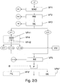
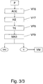
- the light fraction LF (crude fluff) thus produced is replaced by that in the Fig. 2 and 3 Process shown refines, wherein in the Fig.2 the first part of the method (method steps VF1 to VF5 or optional method steps VF6 ', VF6 ") and in the Fig. 3 the second part of the method (method steps VF6 to VF9) is shown.
- the light fraction LF is subjected in a first process step VF1 to the deposition of the ferromagnetic constituents FE, which were digested during the comminution in process step V5.
- a magnetic separator MA2 for example a magnetic drum or an overband magnet device, is used for this purpose.
- a mechanical stress in particular an impact treatment, preferably in a rotor impact mill or in a hammer mill HM, wherein metal or copper wires and strands present in the material are sphered.
- the material is subjected to a classification, preferably by means of a sieve device SE with a hole diameter of 5-8 mm.
- a classification preferably by means of a sieve device SE with a hole diameter of 5-8 mm.
- the second light fraction class LF2 has predominantly lint-like consistency.
- the first light fraction class LF1 is subjected to a density separation, the method step VF4 being subdivided into the method steps VF41 and VF42.
- the light material fraction LF1 is fed to an air classifier WSR with a zigzag-shaped, approximately vertically aligned suction channel.
- the suction air flow in the suction channel can be regulated by means of a frequency-controlled blower and is regulated as a function of the density or specific density of the introduced light fraction LF1.
- the light fraction substantially freed from the dust is fed to a separation table TT.
- This is adjustable in terms of its acting on the light fraction to be separated air flow, its Rüttelamplitude and its inclination.
- the light fraction class LF1 is separated by the separation table TT into a light material fraction LF1-LG and a heavy material fraction LF1-SG.
- the heavy material fraction LF1-SG has a granular consistency with an average bulk density of about 400-500 kg / m3 and contains copper in the form of strands or wires.
- the heavy material fraction LF1-SG is fed to a further processing module VM, which is not the subject of the present invention.
- the light material fraction LF1-LG is subjected to a cleaning by a special cleaning device RE in a subsequent process step VF5.
- the cleaning device RE comprises at least one centrifuge in which a dry surface cleaning of the light material fraction LF1-LG takes place.
- the light material fraction LF1-LG is dedusted by means of the centrifuge, ie freed from heavy metal-contaminated dust STF2 (i.w. containing lead and zinc).
- the thus purified light material fraction LF1-LG can be fed to a pelletizing unit VF6 'in a pelletizer PE or a briquetting unit VF6 "in a briquetting unit BE, but it is preferably fed to an agglomeration VF6 (LF1-LG) -Fraction LF1-LG is carried out in a suitable agglomeration AGE at about 100 ° C to 180 ° C, preferably at about 140 ° C to 170 ° C after a discontinuous process, until a free-flowing consistency of the material to be processed (LF1-LG) is reached.
- a suitable agglomeration AGE at about 100 ° C to 180 ° C, preferably at about 140 ° C to 170 ° C after a discontinuous process, until a free-flowing consistency of the material to be processed (LF1-LG) is reached.
- the agglomerate formed by the agglomeration VF6 is already cooled in the agglomerator by means of cooling water to about 50-60 ° C.
- suitable (not shown) means may be provided to subject the agglomerate to agglomeration of a gas-based extraction of pollutants.
- the agglomerate can then be further cooled down to ambient temperature (VF7) by means of a cooling device KE.
- the cooling device KE can work with water here.
- it is also conceivable cooling by means of air for example air of a Lucas-gebläses.
- drying VF8 is recommended by means of a suitable drying device TE.
- the drying VF8 can be done for example by air, even with heated air.
- the method steps VF7 and VF8 can also be operated in parallel.
- the agglomerate is fed to a metal deposit VF9, wherein a neodymium magnet which achieves very high separation performance with small dimensions is preferably used as the metal separator MA3.
- the metal deposition device MA3 the magnetic (during the agglomeration process, the lint-type material (LF1-LG) was slightly magnetic due to impregnation with ferromagnetic particles) is separated from the non-magnetic, predominantly copper-containing materials.
- a high-purity shredder lint agglomerate (SFA) and a copper / plastic granulate G are produced as end products.
- the copper / plastic granulate G (like the heavy material LF1-SG) is likewise fed to the further processing module VM which, as already mentioned, is not the subject of the present invention ,
Landscapes
- Engineering & Computer Science (AREA)
- Environmental & Geological Engineering (AREA)
- Mechanical Engineering (AREA)
- Chemical & Material Sciences (AREA)
- Manufacturing & Machinery (AREA)
- Geology (AREA)
- General Life Sciences & Earth Sciences (AREA)
- Life Sciences & Earth Sciences (AREA)
- Materials Engineering (AREA)
- Metallurgy (AREA)
- Organic Chemistry (AREA)
- Processing Of Solid Wastes (AREA)
- Combined Means For Separation Of Solids (AREA)
- Manufacture And Refinement Of Metals (AREA)
- Separation, Recovery Or Treatment Of Waste Materials Containing Plastics (AREA)
Claims (42)
- Procédé de préparation d'une fraction légère (LF) qui a été formée pendant le traitement de déchets (KA) pauvres en métaux et riches en matière synthétique, le procédé présentant les étapes suivantes :application (VF2) de percussions et/ou d'impacts sur la fraction légère (LF),criblage (VF3) de la fraction légère (LF) en au moins deux classes (LF1 et LF2) de fraction légère,séparation (VF4) d'au moins une classe (LF1) de fraction légère en au moins une fraction de poussière (STF1) et au moins une autre fraction (LF1-LG, LF1-SG),une séparation (VF41) de la fraction de poussière (STF1) s'effectuant essentiellement par l'intermédiaire du contrôle du temps de séjour de la classe (LF1) de fraction légère dans au moins un moyen de traitement (WSR) qui participe à la séparation (VF41).
- Procédé selon la revendication 1, caractérisé en ce que le temps de séjour de la classe (LF1) de fraction légère dans le moyen de traitement (WSR) est contrôlé par l'intermédiaire d'une aspiration réglable.
- Procédé selon la revendication 2, caractérisé en ce que l'aspiration présente un débit d'air d'aspiration qui est régulé en fonction de la densité de la ou des classes (LF1) de fraction légère.
- Procédé selon la revendication 3, caractérisé en ce que la vitesse de l'écoulement d'air d'aspiration est régulée de manière proportionnelle à la densité de la ou des classes (LF1) de fraction légère.
- Procédé selon au moins l'une des revendications 1 à 4, caractérisé en ce qu'en plus d'être séparée de la fraction de poussière (STF1), la classe (LF1) de fraction légère est séparée (VF42) en au moins une fraction (LF1-LG) de matière légère et une fraction (LF1-SG) de matière lourde.
- Procédé selon la revendication 5, caractérisé en ce que la ou les fractions (LF1-LG) de matière légère sont nettoyées (VF5).
- Procédé selon la revendication 6, caractérisé en ce que le nettoyage (VF5) s'effectue par dépoussiérage.
- Procédé selon au moins l'une des revendications précédentes, caractérisé en ce que le criblage (VF3) de la fraction légère (LF) s'effectue par tamisage à un diamètre de trous compris entre environ 5 et 8 mm.
- Procédé selon au moins l'une des revendications précédentes, caractérisé en ce que par le criblage (VF3) de la fraction légère (LF), on forme au moins une première classe (LF1) de fraction légère dont les particules ont une taille < 5 à 8 mm et une deuxième classe (LF2) de fraction légère dont les particules ont une taille moyenne > 5 à 8 mm.
- Procédé selon au moins l'une des revendications précédentes, caractérisé en ce que la fraction (LF1-LG) de matière légère obtenue par la séparation (VF4) présente en moyenne une masse spécifique en vrac de < 250 kg/m3 et la fraction (LF1-SG) de matière lourde en moyenne une masse spécifique en vrac > 250 kg/m3.
- Procédé selon au moins l'une des revendications précédentes, caractérisé en ce que la fraction légère (LF) est une fraction légère riche en fibres.
- Procédé selon les revendications 1 ou 2, caractérisé en ce que les déchets pauvres en métaux et riches en matière synthétique sont au moins en partie des déchets contenant des métaux provenant de résidus de déchiquetage.
- Procédé selon au moins l'une des revendications précédentes, caractérisé en ce que pour former la fraction légère (LF), au moins les étapes (V1 à V7) suivantes sont exécutées successivement pendant la préparation des déchets (KA) pauvres en métaux et riches en matière synthétique :séparation (V1) des composants ferromagnétiques (FE),séparation (V2) d'une première fraction (RS1) de sable brut,séparation (V3) des composants métalliques non ferromagnétiques (NE),séparation (V4) des composants grossiers (SG),déchiquetage (V5),séparation (V6) d'une deuxième fraction (RS2) de sable brut,tri (V7) en au moins une fraction légère (LF) et une fraction lourde (SF).
- Procédé selon au moins l'une des revendications précédentes, caractérisé en ce qu'une séparation (VF1) des FE s'effectue avant le traitement (VF2) par percussion.
- Procédé selon au moins l'une des revendications 6 à 14, caractérisé en ce que la fraction (LF1-LG) de matière légère subit une agglomération (VF6) avant son nettoyage (VF5).
- Procédé selon la revendication 15, caractérisé en ce que l'agglomération (VF6) s'effectue entre environ 100°C et 180°C.
- Procédé selon au moins l'une des revendications 15 et 16 qui précèdent, caractérisé en ce que la fraction (LF1-LG) de matière légère est encore refroidie (VF7) après l'agglomération (VF6).
- Procédé selon la revendication 17, caractérisé en ce que le refroidissement (VF7) s'effectue sensiblement à température ambiante.
- Procédé selon au moins l'une des revendications 15 à 18 qui précèdent, caractérisé en ce que la fraction (LF1-LG) de matière légère est encore séchée (VF8) après l'agglomération (VF6).
- Procédé selon au moins l'une des revendications 15 à 19 qui précèdent, caractérisé en ce que la fraction (LF1-LG) de matière légère subit une séparation (VF9) de métaux après l'agglomération (VF6).
- Procédé selon au moins l'une des revendications 15 à 20 qui précèdent, caractérisé en ce que la fraction (LF1-LG) de matière légère est amenée à un tampon (P) avant l'agglomération (VF6).
- Procédé selon au moins l'une des revendications 6 à 21 qui précèdent, caractérisé en ce que la fraction (LF1-LG) de matière légère subit une pelletisation (VF6') après le nettoyage (VF5).
- Procédé selon au moins l'une des revendications 6 à 22 qui précèdent, caractérisé en ce que la fraction (LF1-LG) de matière légère subit une transformation (VF6") en briquettes après le nettoyage (VF5).
- Procédé selon au moins l'une des revendications précédentes, caractérisé en ce que la fraction (LF1-LG) de matière légère obtenue par la séparation (VF4) est réunie avec au moins une des classes (LF2) de fraction légère obtenue par le tri (VF3) qui précède.
- Procédé selon au moins l'une des revendications 15 à 24 qui précèdent, caractérisé en ce que l'aggloméré subit une extraction au gaz des produits toxiques après l'agglomération (VF6).
- Installation de préparation d'une fraction légère (LF) qui a été formée par le traitement de déchets (KA) pauvres en métaux et riches en matière synthétique, caractérisée en ce qu'elle présente des moyens (MA2, HM, SE, WSR, TT, RE, AGE, KE, TE MA3) qui permettent de mettre en oeuvre successivement les étapes de traitement suivantes :application (VF2) de percussions et/ou d'impacts sur la fraction légère (LF),criblage (VF3) de la fraction légère (LF) en au moins deux classes (LF1 et LF2) de fraction légère,séparation (VF4) d'au moins une classe (LF1) de fraction légère en au moins une fraction de poussière (STF1) et au moins une autre fraction (LF1-LG, LF1-SG),une séparation (VF41) de la fraction de poussière (STF1) s'effectuant essentiellement par l'intermédiaire du contrôle du temps de séjour de la classe (LF1) de fraction légère dans au moins un moyen de traitement (WSR) qui participe à la séparation (VF41).
- Installation selon la revendication 26, caractérisée en ce que le moyen de traitement (WSR) qui participe à la séparation (VF41) présentent des moyens d'aspiration réglables de la fraction de poussière (STF1).
- Installation selon les revendications 26 ou 27, caractérisée en ce que le moyen (WSR) qui participe à la séparation (VF41) comporte un canal d'aspiration en zigzag.
- Installation selon au moins l'une des revendications 27 à 28 qui précèdent, caractérisée en ce que les moyens d'aspiration réglables des poussières comprennent au moins un ventilateur commandé en fréquence.
- Installation selon au moins l'une des revendications 26 à 29 qui précèdent, caractérisée en ce que le moyen de traitement (WSR) qui participe à la séparation (VF41) est suivi par au moins une table de séparation (TT) qui sépare la fraction résiduelle séparée après la séparation (VF41) en au moins une fraction (LF1-LG) de matière légère et une fraction (LF1-SG) de matière lourde (VF42).
- Installation selon la revendication 30, caractérisée en ce que l'écoulement d'air qui agit sur la matière à séparer, l'amplitude des secousses et/ou l'inclinaison de la table de séparation (TT) peuvent être réglées.
- Installation selon au moins l'une des revendications 26 à 31 qui précèdent, caractérisée en ce que les moyens (HM) qui appliquent (VF2) une percussion et/ou des impacts sur la fraction légère (LF) sont prévus sous la forme d'au moins un broyeur à rotor ou au moins un broyeur à marteaux.
- Installation selon la revendication 32, caractérisée en ce que lorsqu'un broyeur à rotor est utilisé, la distance entre le stator et le rotor est comprise entre 3 mm et 5 mm.
- Installation selon la revendication 32, caractérisée en ce que lorsqu'un broyeur à marteaux est utilisé, ses perforations de tamisage présentent des trous d'un diamètre compris entre 8 et 15 mm et ses outils de percussion d'une largeur comprise entre 6 mm et 14 mm.
- Installation selon au moins l'une des revendications 26 à 34 qui précèdent, caractérisée en ce que les moyens (HM) d'application (VF2) de percussions et/ou d'impacts sur la fraction légère (LF) sont précédés par des moyens (MA2) de séparation des composants ferromagnétiques (FE).
- Installation selon au moins l'une des revendications 26 à 35 qui précèdent, caractérisée en ce que les moyens (HM) d'application (VF2) de percussions et/ou d'impacts sur la fraction légère (LF) sont suivis par un dispositif de criblage qui présente la forme d'un dispositif de tamisage (SE) dont les trous sont d'environ 5 à 8 mm.
- Installation selon au moins l'une des revendications 30 à 36 qui précèdent, caractérisée en ce que la table de séparation (TT) est suivie par des moyens (RE) de nettoyage de surface d'au moins la fraction (LF1-LG) de matière légère.
- Installation selon la revendication 37, caractérisée en ce que les moyens (RE) de nettoyage de surface sont suivis par un dispositif d'agglomération (AGE).
- Installation selon la revendication 38, caractérisée en ce que le dispositif d'agglomération (AGE) est précédé par un tampon (P).
- Installation selon au moins l'une des revendications 38 à 39 qui précèdent, caractérisée en ce que le dispositif d'agglomération (AGE) est suivi par des moyens de refroidissement et de séchage (KE, TE).
- Installation selon au moins l'une des revendications 38 à 40 qui précèdent, caractérisée en ce que le dispositif d'agglomération (AGE) est suivi par des moyens (MA3) de séparation de métaux ferromagnétiques.
- Installation selon au moins l'une des revendications 38 à 41 qui précèdent, caractérisée en ce qu'elle présente des moyens qui permettent de faire subir à l'aggloméré une extraction au gaz de substances toxiques après l'agglomération.
Applications Claiming Priority (4)
| Application Number | Priority Date | Filing Date | Title |
|---|---|---|---|
| DE102008018527 | 2008-04-12 | ||
| DE200810026417 DE102008026417A1 (de) | 2008-04-12 | 2008-06-02 | Verfahren und Anlage zur Aufbereitung von kunststoffreichen Abfällen |
| DE102008026416A DE102008026416A1 (de) | 2008-04-12 | 2008-06-02 | Verfahren und Anlage zur Aufbereitung von Kunststoffabfällen |
| PCT/EP2009/002104 WO2009124651A1 (fr) | 2008-04-12 | 2009-03-21 | Procédé et installation pour le traitement de déchets à teneur élevée en matières plastiques |
Publications (2)
| Publication Number | Publication Date |
|---|---|
| EP2268406A1 EP2268406A1 (fr) | 2011-01-05 |
| EP2268406B1 true EP2268406B1 (fr) | 2017-04-19 |
Family
ID=41060697
Family Applications (2)
| Application Number | Title | Priority Date | Filing Date |
|---|---|---|---|
| EP09730411.7A Active EP2271430B1 (fr) | 2008-04-12 | 2009-03-21 | Procédé et installation pour le traitement de déchets de matières plastiques |
| EP09731075.9A Active EP2268406B1 (fr) | 2008-04-12 | 2009-03-21 | Procédé et installation pour le traitement de déchets à teneur élevée en matières plastiques |
Family Applications Before (1)
| Application Number | Title | Priority Date | Filing Date |
|---|---|---|---|
| EP09730411.7A Active EP2271430B1 (fr) | 2008-04-12 | 2009-03-21 | Procédé et installation pour le traitement de déchets de matières plastiques |
Country Status (7)
| Country | Link |
|---|---|
| US (2) | US8616378B2 (fr) |
| EP (2) | EP2271430B1 (fr) |
| CN (2) | CN101998886B (fr) |
| BR (2) | BRPI0911655B1 (fr) |
| DE (2) | DE102008026416A1 (fr) |
| RU (2) | RU2471576C2 (fr) |
| WO (2) | WO2009124651A1 (fr) |
Families Citing this family (11)
| Publication number | Priority date | Publication date | Assignee | Title |
|---|---|---|---|---|
| EP2321104B1 (fr) | 2008-06-26 | 2013-10-09 | Re Community Energy, LLC | Procédé pour le stockage de déchets intégré |
| NL2005946C2 (en) | 2010-12-31 | 2012-07-03 | Holland Composites Innovations B V | Composite materials and shaped articles. |
| NL2005945C2 (en) * | 2010-12-31 | 2012-07-03 | Holland Composites Innovations B V | Composite materials and shaped articles. |
| CN107513443A (zh) | 2011-06-03 | 2017-12-26 | 谐和能源有限责任公司 | 由废物材料制备过程设计燃料原料的系统和方法 |
| US9000318B2 (en) * | 2012-06-25 | 2015-04-07 | International Business Machines Corporation | Identification of plastic material composition |
| US9192984B2 (en) * | 2012-10-29 | 2015-11-24 | Francis A. Lesters | Waste foundry sand to frac sand process |
| US20140221553A1 (en) * | 2013-02-07 | 2014-08-07 | Holland Composites Innovation B.V. | Composite materials and shaped articles |
| NL2016193B1 (en) | 2016-02-01 | 2017-01-02 | Arn Holding B V | Process for preparing automotive shredder fibre residue pellets. |
| RU2753797C1 (ru) * | 2020-07-10 | 2021-08-23 | Общество С Ограниченной Ответственностью "Научно-Производственное Объединение "Экоспас" | Установка мобильная термической утилизации и способ её использования |
| JP2023043031A (ja) * | 2021-09-15 | 2023-03-28 | 太平洋セメント株式会社 | 水銀低減廃プラスチックの製造方法 |
| EP4163075A1 (fr) * | 2021-12-21 | 2023-04-12 | Mater A/S | Procédé de production d'un article fabriqué à partir de déchets thermoplastiques et fibreux et matériau composite comprenant des déchets thermoplastiques et fibreux |
Family Cites Families (45)
| Publication number | Priority date | Publication date | Assignee | Title |
|---|---|---|---|---|
| US3738483A (en) * | 1971-11-08 | 1973-06-12 | Kenzie H Mac | Method of and means for classification of heterogeneous shredded refuse materials |
| AT350486B (de) * | 1975-02-27 | 1979-06-11 | Goergen Fritz Aurel | Verfahren und vorrichtung zum abscheiden ver- schiedener fraktionen aus muell |
| US4026678A (en) * | 1975-12-17 | 1977-05-31 | Guaranty Performance Co., Inc. | Process for treating municipal wastes to produce a fuel |
| US4245999A (en) | 1978-08-25 | 1981-01-20 | Kenneth S. Safe, Jr. | Method and apparatus for obtaining low ash content refuse fuel, paper and plastic products from municipal solid waste and said products |
| NL190634C (nl) * | 1980-12-24 | 1994-06-01 | Orfa Ag | Werkwijze voor het verwerken van afval tot ondermeer vezelachtig materiaal. |
| US4874134A (en) * | 1988-07-18 | 1989-10-17 | Wiens Thomas J | Solid waste processing facility and process |
| US5184780A (en) | 1988-07-18 | 1993-02-09 | First Dominion Holdings, Inc. | Solid waste disposal |
| SU1685721A1 (ru) * | 1989-06-05 | 1991-10-23 | Всесоюзный научно-исследовательский и проектный институт по вторичным черным металлам | Способ переработки изношенных покрышек с металлокордом |
| ATE121969T1 (de) | 1989-09-12 | 1995-05-15 | Inter Recycling Ag | Verfahren zur materialtrennung von gemischt anfallenden gegenständen aus nichtmetall und nichtmagnetischem metall. |
| DE4031417A1 (de) * | 1990-10-04 | 1992-04-09 | Peter Prof Dr Kraus | Verfahren zur auftrennung von metallhaltigen muellkomponenten |
| DE4100346A1 (de) * | 1991-01-08 | 1992-07-09 | Preussag Ag | Verfahren zur mechanischen aufbereitung von unsortiertem geraeteschrott |
| DE4205309A1 (de) | 1992-02-21 | 1993-08-26 | Preussag Ag | Verfahren zur aufbereitung von reststoffen aus altautomobilen |
| DE4222379A1 (de) | 1992-07-08 | 1994-01-13 | Finkenrath Industrieverwaltung | Verfahren und Vorrichtung zur Aufbereitung von Rohmüll, insbesondere Haus- und Gewerbemüll |
| DE4301066A1 (de) | 1993-01-16 | 1994-07-21 | Igu Umweltschutzanlagen | Verfahren und Vorrichtung zum Aufbereiten von Kunststoffabfall |
| DE4306781A1 (de) | 1993-03-04 | 1994-09-08 | Kloeckner Humboldt Deutz Ag | Verfahren und Anlage zur Aufbereitung von kunststoffreichen Müllgemischen |
| DE4314759A1 (de) | 1993-05-05 | 1994-11-10 | Kloeckner Humboldt Deutz Ag | Verfahren und Anlage zur mechanischen Aufbereitung von Abfallgemischen |
| RU2060883C1 (ru) * | 1993-11-30 | 1996-05-27 | Мартынов Василий Егорович | Установка для регенерации резины, металла и текстиля из покрышек |
| US5527432A (en) | 1994-01-28 | 1996-06-18 | Advanced Fiber Technology, Inc. | Method of dry separating fibers from paper making waste sludge and fiber product thereof |
| DE4426503C2 (de) | 1994-07-27 | 1996-07-11 | Noell Abfall & Energietech | Verfahren zur Aufbereitung von Shredderleichtmüll |
| DE4437852A1 (de) | 1994-10-22 | 1996-05-02 | Heckett Multiserv Plc | Verfahren zum Aufbereiten von Shredderrückständen |
| DE4442631C2 (de) | 1994-12-01 | 2002-02-07 | Svedala Lindemann Gmbh | Verfahren und Anlage zur Aufbereitung der in Shredderanlagen anfallenden Leichtfraktion |
| DE19500224A1 (de) * | 1995-01-05 | 1996-07-18 | Dietmar Guschall | Verfahren zur Aufbereitung von Mischkunststoffen |
| AU3765497A (en) | 1996-07-10 | 1998-02-02 | Guschall, Dietmar | Process and system for treatment of mixed plastic materials |
| DE19629473C2 (de) * | 1996-07-10 | 2001-06-13 | Sicon Gmbh | Verfahren und Vorrichtung zur Aufbereitung eines Kunststoffgemisches |
| DE19629470C2 (de) | 1996-07-10 | 2001-12-13 | Sicon Gmbh | Verfahren und Anlage zur Aufbereitung von Mischkunststoffen |
| DE19724860A1 (de) * | 1997-06-12 | 1998-12-17 | Krc Umwelttechnik Gmbh | Verfahren und Vorrichtung zur Aufbereitung einer Shredderleichtfraktion mit Metallteilen |
| DE19755629A1 (de) | 1997-12-15 | 1999-06-24 | Uwh Ges Fuer Thermische Ruecks | Verfahren zur Aufbereitung der Shredderleichtfraktion aus Shredderanlagen |
| JP3541127B2 (ja) * | 1998-08-13 | 2004-07-07 | エンヴィテック株式会社 | シュレッダーダストの処理方法 |
| US6372085B1 (en) * | 1998-12-18 | 2002-04-16 | Kimberly-Clark Worldwide, Inc. | Recovery of fibers from a fiber processing waste sludge |
| EP1020225A1 (fr) | 1999-01-04 | 2000-07-19 | R.S.T. Luxembourg S.A. | Procédé pour séparer des groupes organiques de matériaux à partir de fractions légères de broyage d'automobiles |
| US6422616B1 (en) | 1999-03-01 | 2002-07-23 | Dura Global Technologies, Inc. | Adjustable hood latch assembly |
| DE19911010A1 (de) * | 1999-03-12 | 2000-10-05 | Georg Schons | Anlage und Verfahren für die Verwendung von Shredderabfällen o. dgl. Verbundstoffen sowie Verwendung einer Rotorprallmühle |
| DE19915481A1 (de) | 1999-04-07 | 2000-10-12 | Lsd Umwelt Und Recyclingtechno | Verfahren zur Gewinnung organischer und anorganischer Bestandteile aus Materialien einer Shredderleichtfraktion sowie Anlage zur Durchführung eines entsprechenden Verfahrens |
| US6974097B2 (en) | 2000-06-01 | 2005-12-13 | Simon Jonathan L | Method and apparatus for sorting recyclable products |
| US6422493B1 (en) | 2000-06-01 | 2002-07-23 | Simon Family Partners | Method and apparatus for sorting recyclable products |
| DE10053488A1 (de) * | 2000-10-27 | 2002-05-08 | Volkswagen Ag | Anlage und Verfahren zur Aufbereitung von Shredder-Rückständen und Verwendung einer erzeugten Granulat-Fraktion |
| DE10053491A1 (de) | 2000-10-27 | 2002-05-08 | Volkswagen Ag | Anlage und Verfahren zur Aufbereitung von Shredder-Rückständen und Verfahren einer erzeugten Flusen-Fraktion |
| DE10053487A1 (de) | 2000-10-27 | 2002-05-08 | Volkswagen Ag | Anlage und Verfahren zur Aufbereitung von Shredder-Rückständen |
| DE10224133A1 (de) | 2001-08-22 | 2003-03-06 | Emschergenossenschaft Lippever | Verfahren zur Behandlung von Schlamm |
| DE10206765B4 (de) | 2002-02-19 | 2005-12-15 | Daimlerchrysler Ag | Schlossanordnung einer Fahrzeughaube |
| EP1578575B1 (fr) | 2002-07-22 | 2015-09-09 | MBA Polymers, Inc. | Systeme transportable de recuperation du plastique et procede de son utilisation |
| DE102004045821B4 (de) | 2003-07-28 | 2008-01-03 | SRW Sächsische Recyclingwerke GmbH | Verfahren und Anlage zur Aufbereitung der Schredderleichtfraktion aus der Zerkleinerung von Schrotten und metallischen Abfällen |
| DE10334646B4 (de) * | 2003-07-28 | 2006-04-27 | SRW Sächsische Recyclingwerke GmbH | Verfahren und Anlage zur Aufbereitung der Shredderleichtfraktion aus der Zerkleinerung von Schrotten und metallhaltigen Abfällen |
| DE10336802B4 (de) * | 2003-08-11 | 2017-02-16 | Alexander Koslow | Verfahren und Anlage zum Trennen und Sortieren insbesondere von vorzerkleinerten Stoffen |
| DE102009009873A1 (de) | 2008-03-31 | 2009-10-01 | Volkswagen Ag | Verfahren und Anlage zur Aufbereitung einer schweren, kunststoffreichen Fraktion |
-
2008
- 2008-06-02 DE DE102008026416A patent/DE102008026416A1/de not_active Withdrawn
- 2008-06-02 DE DE200810026417 patent/DE102008026417A1/de not_active Withdrawn
-
2009
- 2009-03-21 WO PCT/EP2009/002104 patent/WO2009124651A1/fr not_active Ceased
- 2009-03-21 CN CN200980112875.8A patent/CN101998886B/zh active Active
- 2009-03-21 BR BRPI0911655-9A patent/BRPI0911655B1/pt not_active IP Right Cessation
- 2009-03-21 US US12/937,524 patent/US8616378B2/en not_active Expired - Fee Related
- 2009-03-21 US US12/937,519 patent/US8985339B2/en not_active Expired - Fee Related
- 2009-03-21 CN CN200980112874.3A patent/CN101998885B/zh active Active
- 2009-03-21 RU RU2010146082/03A patent/RU2471576C2/ru active
- 2009-03-21 RU RU2010146080/03A patent/RU2471575C2/ru not_active IP Right Cessation
- 2009-03-21 WO PCT/EP2009/002103 patent/WO2009124650A1/fr not_active Ceased
- 2009-03-21 BR BRPI0909013A patent/BRPI0909013A2/pt not_active Application Discontinuation
- 2009-03-21 EP EP09730411.7A patent/EP2271430B1/fr active Active
- 2009-03-21 EP EP09731075.9A patent/EP2268406B1/fr active Active
Also Published As
| Publication number | Publication date |
|---|---|
| DE102008026417A1 (de) | 2009-10-15 |
| CN101998885A (zh) | 2011-03-30 |
| US20110114540A1 (en) | 2011-05-19 |
| WO2009124650A1 (fr) | 2009-10-15 |
| BRPI0911655A2 (pt) | 2015-10-13 |
| DE102008026416A1 (de) | 2009-10-15 |
| CN101998886A (zh) | 2011-03-30 |
| US8985339B2 (en) | 2015-03-24 |
| RU2471575C2 (ru) | 2013-01-10 |
| EP2271430B1 (fr) | 2018-08-01 |
| RU2010146082A (ru) | 2012-05-20 |
| US20110094941A1 (en) | 2011-04-28 |
| CN101998886B (zh) | 2014-02-12 |
| RU2010146080A (ru) | 2012-05-20 |
| BRPI0909013A2 (pt) | 2015-09-22 |
| EP2268406A1 (fr) | 2011-01-05 |
| RU2471576C2 (ru) | 2013-01-10 |
| CN101998885B (zh) | 2014-04-30 |
| EP2271430A1 (fr) | 2011-01-12 |
| WO2009124651A1 (fr) | 2009-10-15 |
| US8616378B2 (en) | 2013-12-31 |
| BRPI0911655B1 (pt) | 2020-02-18 |
Similar Documents
| Publication | Publication Date | Title |
|---|---|---|
| EP2268406B1 (fr) | Procédé et installation pour le traitement de déchets à teneur élevée en matières plastiques | |
| DE69816070T2 (de) | Verfahren zur Behandlung von Schredderstaub | |
| EP2274103B1 (fr) | Procédé et installation pour préparer une fraction lourde riche en matières plastiques | |
| EP1332001B1 (fr) | Installation et procede pour traiter des residus de dechiquetage et utilisation d'une fraction de granulat ainsi produite | |
| EP1333931B1 (fr) | Installation et procede de traitement de residus de dechiquetage et utilisation d'une fraction de dechiquetage produite | |
| EP1372860A1 (fr) | Installation et procede de traitement de minerais metalliferes | |
| DE10053487A1 (de) | Anlage und Verfahren zur Aufbereitung von Shredder-Rückständen | |
| EP1332002B1 (fr) | Installation et procede pour traiter des residus de dechiquetage et utilisation d'une fraction de sable ainsi produite | |
| DE19724860A1 (de) | Verfahren und Vorrichtung zur Aufbereitung einer Shredderleichtfraktion mit Metallteilen | |
| WO1994014542A1 (fr) | Procede et dispositif pour la separation mecanique de melanges de matieres plastiques ou de matieres plastiques composites contenant des metaux | |
| DE102004045821B4 (de) | Verfahren und Anlage zur Aufbereitung der Schredderleichtfraktion aus der Zerkleinerung von Schrotten und metallischen Abfällen | |
| EP1786564B1 (fr) | Installation pour le traitement selectif de dechets non tries ou pretries | |
| EP2254701B1 (fr) | Procédé et installation pour le traitement de déchets de matières plastiques à faible teneur en métaux |
Legal Events
| Date | Code | Title | Description |
|---|---|---|---|
| PUAI | Public reference made under article 153(3) epc to a published international application that has entered the european phase |
Free format text: ORIGINAL CODE: 0009012 |
|
| 17P | Request for examination filed |
Effective date: 20101112 |
|
| AK | Designated contracting states |
Kind code of ref document: A1 Designated state(s): AT BE BG CH CY CZ DE DK EE ES FI FR GB GR HR HU IE IS IT LI LT LU LV MC MK MT NL NO PL PT RO SE SI SK TR |
|
| AX | Request for extension of the european patent |
Extension state: AL BA RS |
|
| DAX | Request for extension of the european patent (deleted) | ||
| RAP1 | Party data changed (applicant data changed or rights of an application transferred) |
Owner name: VOLKSWAGEN AKTIENGESELLSCHAFT Owner name: SICON GMBH |
|
| GRAP | Despatch of communication of intention to grant a patent |
Free format text: ORIGINAL CODE: EPIDOSNIGR1 |
|
| INTG | Intention to grant announced |
Effective date: 20161129 |
|
| GRAS | Grant fee paid |
Free format text: ORIGINAL CODE: EPIDOSNIGR3 |
|
| GRAA | (expected) grant |
Free format text: ORIGINAL CODE: 0009210 |
|
| AK | Designated contracting states |
Kind code of ref document: B1 Designated state(s): AT BE BG CH CY CZ DE DK EE ES FI FR GB GR HR HU IE IS IT LI LT LU LV MC MK MT NL NO PL PT RO SE SI SK TR |
|
| REG | Reference to a national code |
Ref country code: GB Ref legal event code: FG4D Free format text: NOT ENGLISH |
|
| REG | Reference to a national code |
Ref country code: CH Ref legal event code: EP |
|
| REG | Reference to a national code |
Ref country code: AT Ref legal event code: REF Ref document number: 885432 Country of ref document: AT Kind code of ref document: T Effective date: 20170515 |
|
| REG | Reference to a national code |
Ref country code: IE Ref legal event code: FG4D Free format text: LANGUAGE OF EP DOCUMENT: GERMAN |
|
| REG | Reference to a national code |
Ref country code: DE Ref legal event code: R096 Ref document number: 502009013885 Country of ref document: DE |
|
| REG | Reference to a national code |
Ref country code: NL Ref legal event code: MP Effective date: 20170419 |
|
| REG | Reference to a national code |
Ref country code: LT Ref legal event code: MG4D |
|
| PG25 | Lapsed in a contracting state [announced via postgrant information from national office to epo] |
Ref country code: NL Free format text: LAPSE BECAUSE OF FAILURE TO SUBMIT A TRANSLATION OF THE DESCRIPTION OR TO PAY THE FEE WITHIN THE PRESCRIBED TIME-LIMIT Effective date: 20170419 |
|
| PG25 | Lapsed in a contracting state [announced via postgrant information from national office to epo] |
Ref country code: LT Free format text: LAPSE BECAUSE OF FAILURE TO SUBMIT A TRANSLATION OF THE DESCRIPTION OR TO PAY THE FEE WITHIN THE PRESCRIBED TIME-LIMIT Effective date: 20170419 Ref country code: NO Free format text: LAPSE BECAUSE OF FAILURE TO SUBMIT A TRANSLATION OF THE DESCRIPTION OR TO PAY THE FEE WITHIN THE PRESCRIBED TIME-LIMIT Effective date: 20170719 Ref country code: GR Free format text: LAPSE BECAUSE OF FAILURE TO SUBMIT A TRANSLATION OF THE DESCRIPTION OR TO PAY THE FEE WITHIN THE PRESCRIBED TIME-LIMIT Effective date: 20170720 Ref country code: HR Free format text: LAPSE BECAUSE OF FAILURE TO SUBMIT A TRANSLATION OF THE DESCRIPTION OR TO PAY THE FEE WITHIN THE PRESCRIBED TIME-LIMIT Effective date: 20170419 Ref country code: ES Free format text: LAPSE BECAUSE OF FAILURE TO SUBMIT A TRANSLATION OF THE DESCRIPTION OR TO PAY THE FEE WITHIN THE PRESCRIBED TIME-LIMIT Effective date: 20170419 Ref country code: FI Free format text: LAPSE BECAUSE OF FAILURE TO SUBMIT A TRANSLATION OF THE DESCRIPTION OR TO PAY THE FEE WITHIN THE PRESCRIBED TIME-LIMIT Effective date: 20170419 |
|
| PG25 | Lapsed in a contracting state [announced via postgrant information from national office to epo] |
Ref country code: IS Free format text: LAPSE BECAUSE OF FAILURE TO SUBMIT A TRANSLATION OF THE DESCRIPTION OR TO PAY THE FEE WITHIN THE PRESCRIBED TIME-LIMIT Effective date: 20170819 Ref country code: PL Free format text: LAPSE BECAUSE OF FAILURE TO SUBMIT A TRANSLATION OF THE DESCRIPTION OR TO PAY THE FEE WITHIN THE PRESCRIBED TIME-LIMIT Effective date: 20170419 Ref country code: LV Free format text: LAPSE BECAUSE OF FAILURE TO SUBMIT A TRANSLATION OF THE DESCRIPTION OR TO PAY THE FEE WITHIN THE PRESCRIBED TIME-LIMIT Effective date: 20170419 Ref country code: BG Free format text: LAPSE BECAUSE OF FAILURE TO SUBMIT A TRANSLATION OF THE DESCRIPTION OR TO PAY THE FEE WITHIN THE PRESCRIBED TIME-LIMIT Effective date: 20170719 Ref country code: SE Free format text: LAPSE BECAUSE OF FAILURE TO SUBMIT A TRANSLATION OF THE DESCRIPTION OR TO PAY THE FEE WITHIN THE PRESCRIBED TIME-LIMIT Effective date: 20170419 |
|
| REG | Reference to a national code |
Ref country code: DE Ref legal event code: R097 Ref document number: 502009013885 Country of ref document: DE |
|
| PG25 | Lapsed in a contracting state [announced via postgrant information from national office to epo] |
Ref country code: SK Free format text: LAPSE BECAUSE OF FAILURE TO SUBMIT A TRANSLATION OF THE DESCRIPTION OR TO PAY THE FEE WITHIN THE PRESCRIBED TIME-LIMIT Effective date: 20170419 Ref country code: DK Free format text: LAPSE BECAUSE OF FAILURE TO SUBMIT A TRANSLATION OF THE DESCRIPTION OR TO PAY THE FEE WITHIN THE PRESCRIBED TIME-LIMIT Effective date: 20170419 Ref country code: RO Free format text: LAPSE BECAUSE OF FAILURE TO SUBMIT A TRANSLATION OF THE DESCRIPTION OR TO PAY THE FEE WITHIN THE PRESCRIBED TIME-LIMIT Effective date: 20170419 Ref country code: EE Free format text: LAPSE BECAUSE OF FAILURE TO SUBMIT A TRANSLATION OF THE DESCRIPTION OR TO PAY THE FEE WITHIN THE PRESCRIBED TIME-LIMIT Effective date: 20170419 Ref country code: CZ Free format text: LAPSE BECAUSE OF FAILURE TO SUBMIT A TRANSLATION OF THE DESCRIPTION OR TO PAY THE FEE WITHIN THE PRESCRIBED TIME-LIMIT Effective date: 20170419 |
|
| PLBE | No opposition filed within time limit |
Free format text: ORIGINAL CODE: 0009261 |
|
| STAA | Information on the status of an ep patent application or granted ep patent |
Free format text: STATUS: NO OPPOSITION FILED WITHIN TIME LIMIT |
|
| PG25 | Lapsed in a contracting state [announced via postgrant information from national office to epo] |
Ref country code: IT Free format text: LAPSE BECAUSE OF FAILURE TO SUBMIT A TRANSLATION OF THE DESCRIPTION OR TO PAY THE FEE WITHIN THE PRESCRIBED TIME-LIMIT Effective date: 20170419 |
|
| 26N | No opposition filed |
Effective date: 20180122 |
|
| PG25 | Lapsed in a contracting state [announced via postgrant information from national office to epo] |
Ref country code: SI Free format text: LAPSE BECAUSE OF FAILURE TO SUBMIT A TRANSLATION OF THE DESCRIPTION OR TO PAY THE FEE WITHIN THE PRESCRIBED TIME-LIMIT Effective date: 20170419 |
|
| PG25 | Lapsed in a contracting state [announced via postgrant information from national office to epo] |
Ref country code: MT Free format text: LAPSE BECAUSE OF FAILURE TO SUBMIT A TRANSLATION OF THE DESCRIPTION OR TO PAY THE FEE WITHIN THE PRESCRIBED TIME-LIMIT Effective date: 20170419 |
|
| REG | Reference to a national code |
Ref country code: CH Ref legal event code: PL |
|
| GBPC | Gb: european patent ceased through non-payment of renewal fee |
Effective date: 20180321 |
|
| PG25 | Lapsed in a contracting state [announced via postgrant information from national office to epo] |
Ref country code: MC Free format text: LAPSE BECAUSE OF FAILURE TO SUBMIT A TRANSLATION OF THE DESCRIPTION OR TO PAY THE FEE WITHIN THE PRESCRIBED TIME-LIMIT Effective date: 20170419 |
|
| REG | Reference to a national code |
Ref country code: BE Ref legal event code: MM Effective date: 20180331 |
|
| REG | Reference to a national code |
Ref country code: IE Ref legal event code: MM4A |
|
| PG25 | Lapsed in a contracting state [announced via postgrant information from national office to epo] |
Ref country code: LU Free format text: LAPSE BECAUSE OF NON-PAYMENT OF DUE FEES Effective date: 20180321 |
|
| PG25 | Lapsed in a contracting state [announced via postgrant information from national office to epo] |
Ref country code: IE Free format text: LAPSE BECAUSE OF NON-PAYMENT OF DUE FEES Effective date: 20180321 |
|
| PG25 | Lapsed in a contracting state [announced via postgrant information from national office to epo] |
Ref country code: CH Free format text: LAPSE BECAUSE OF NON-PAYMENT OF DUE FEES Effective date: 20180331 Ref country code: LI Free format text: LAPSE BECAUSE OF NON-PAYMENT OF DUE FEES Effective date: 20180331 Ref country code: GB Free format text: LAPSE BECAUSE OF NON-PAYMENT OF DUE FEES Effective date: 20180321 Ref country code: BE Free format text: LAPSE BECAUSE OF NON-PAYMENT OF DUE FEES Effective date: 20180331 |
|
| PG25 | Lapsed in a contracting state [announced via postgrant information from national office to epo] |
Ref country code: FR Free format text: LAPSE BECAUSE OF NON-PAYMENT OF DUE FEES Effective date: 20180331 |
|
| REG | Reference to a national code |
Ref country code: AT Ref legal event code: MM01 Ref document number: 885432 Country of ref document: AT Kind code of ref document: T Effective date: 20180321 |
|
| PG25 | Lapsed in a contracting state [announced via postgrant information from national office to epo] |
Ref country code: AT Free format text: LAPSE BECAUSE OF NON-PAYMENT OF DUE FEES Effective date: 20180321 |
|
| PG25 | Lapsed in a contracting state [announced via postgrant information from national office to epo] |
Ref country code: TR Free format text: LAPSE BECAUSE OF FAILURE TO SUBMIT A TRANSLATION OF THE DESCRIPTION OR TO PAY THE FEE WITHIN THE PRESCRIBED TIME-LIMIT Effective date: 20170419 |
|
| PG25 | Lapsed in a contracting state [announced via postgrant information from national office to epo] |
Ref country code: PT Free format text: LAPSE BECAUSE OF FAILURE TO SUBMIT A TRANSLATION OF THE DESCRIPTION OR TO PAY THE FEE WITHIN THE PRESCRIBED TIME-LIMIT Effective date: 20170419 Ref country code: HU Free format text: LAPSE BECAUSE OF FAILURE TO SUBMIT A TRANSLATION OF THE DESCRIPTION OR TO PAY THE FEE WITHIN THE PRESCRIBED TIME-LIMIT; INVALID AB INITIO Effective date: 20090321 |
|
| PG25 | Lapsed in a contracting state [announced via postgrant information from national office to epo] |
Ref country code: MK Free format text: LAPSE BECAUSE OF NON-PAYMENT OF DUE FEES Effective date: 20170419 Ref country code: CY Free format text: LAPSE BECAUSE OF FAILURE TO SUBMIT A TRANSLATION OF THE DESCRIPTION OR TO PAY THE FEE WITHIN THE PRESCRIBED TIME-LIMIT Effective date: 20170419 |
|
| P01 | Opt-out of the competence of the unified patent court (upc) registered |
Effective date: 20230526 |
|
| PGFP | Annual fee paid to national office [announced via postgrant information from national office to epo] |
Ref country code: DE Payment date: 20260331 Year of fee payment: 18 |