EP4163150A1 - Siège inclinable à configurations multiples - Google Patents
Siège inclinable à configurations multiples Download PDFInfo
- Publication number
- EP4163150A1 EP4163150A1 EP22200293.3A EP22200293A EP4163150A1 EP 4163150 A1 EP4163150 A1 EP 4163150A1 EP 22200293 A EP22200293 A EP 22200293A EP 4163150 A1 EP4163150 A1 EP 4163150A1
- Authority
- EP
- European Patent Office
- Prior art keywords
- backrest
- configuration
- linear actuator
- seat
- seat pan
- Prior art date
- Legal status (The legal status is an assumption and is not a legal conclusion. Google has not performed a legal analysis and makes no representation as to the accuracy of the status listed.)
- Pending
Links
- 238000000034 method Methods 0.000 description 10
- 230000007246 mechanism Effects 0.000 description 6
- 238000013016 damping Methods 0.000 description 4
- 238000010586 diagram Methods 0.000 description 2
- 239000000463 material Substances 0.000 description 2
- 230000007935 neutral effect Effects 0.000 description 2
- 239000003381 stabilizer Substances 0.000 description 2
- 230000007704 transition Effects 0.000 description 2
- 230000003247 decreasing effect Effects 0.000 description 1
- 238000006073 displacement reaction Methods 0.000 description 1
- 238000012986 modification Methods 0.000 description 1
- 230000004048 modification Effects 0.000 description 1
Images


Classifications
-
- B—PERFORMING OPERATIONS; TRANSPORTING
- B60—VEHICLES IN GENERAL
- B60N—SEATS SPECIALLY ADAPTED FOR VEHICLES; VEHICLE PASSENGER ACCOMMODATION NOT OTHERWISE PROVIDED FOR
- B60N2/00—Seats specially adapted for vehicles; Arrangement or mounting of seats in vehicles
- B60N2/02—Seats specially adapted for vehicles; Arrangement or mounting of seats in vehicles the seat or part thereof being movable, e.g. adjustable
- B60N2/04—Seats specially adapted for vehicles; Arrangement or mounting of seats in vehicles the seat or part thereof being movable, e.g. adjustable the whole seat being movable
- B60N2/14—Seats specially adapted for vehicles; Arrangement or mounting of seats in vehicles the seat or part thereof being movable, e.g. adjustable the whole seat being movable rotatable, e.g. to permit easy access
-
- B—PERFORMING OPERATIONS; TRANSPORTING
- B60—VEHICLES IN GENERAL
- B60N—SEATS SPECIALLY ADAPTED FOR VEHICLES; VEHICLE PASSENGER ACCOMMODATION NOT OTHERWISE PROVIDED FOR
- B60N2/00—Seats specially adapted for vehicles; Arrangement or mounting of seats in vehicles
- B60N2/02—Seats specially adapted for vehicles; Arrangement or mounting of seats in vehicles the seat or part thereof being movable, e.g. adjustable
- B60N2/22—Seats specially adapted for vehicles; Arrangement or mounting of seats in vehicles the seat or part thereof being movable, e.g. adjustable the back-rest being adjustable
- B60N2/23—Seats specially adapted for vehicles; Arrangement or mounting of seats in vehicles the seat or part thereof being movable, e.g. adjustable the back-rest being adjustable by linear actuators, e.g. linear screw mechanisms
-
- B—PERFORMING OPERATIONS; TRANSPORTING
- B60—VEHICLES IN GENERAL
- B60N—SEATS SPECIALLY ADAPTED FOR VEHICLES; VEHICLE PASSENGER ACCOMMODATION NOT OTHERWISE PROVIDED FOR
- B60N2/00—Seats specially adapted for vehicles; Arrangement or mounting of seats in vehicles
- B60N2/02—Seats specially adapted for vehicles; Arrangement or mounting of seats in vehicles the seat or part thereof being movable, e.g. adjustable
- B60N2/04—Seats specially adapted for vehicles; Arrangement or mounting of seats in vehicles the seat or part thereof being movable, e.g. adjustable the whole seat being movable
- B60N2/16—Seats specially adapted for vehicles; Arrangement or mounting of seats in vehicles the seat or part thereof being movable, e.g. adjustable the whole seat being movable height-adjustable
- B60N2/18—Seats specially adapted for vehicles; Arrangement or mounting of seats in vehicles the seat or part thereof being movable, e.g. adjustable the whole seat being movable height-adjustable the front or the rear portion of the seat being adjustable, e.g. independently of each other
- B60N2/1807—Seats specially adapted for vehicles; Arrangement or mounting of seats in vehicles the seat or part thereof being movable, e.g. adjustable the whole seat being movable height-adjustable the front or the rear portion of the seat being adjustable, e.g. independently of each other characterised by the cinematic
- B60N2/181—Rods
-
- B—PERFORMING OPERATIONS; TRANSPORTING
- B60—VEHICLES IN GENERAL
- B60N—SEATS SPECIALLY ADAPTED FOR VEHICLES; VEHICLE PASSENGER ACCOMMODATION NOT OTHERWISE PROVIDED FOR
- B60N2/00—Seats specially adapted for vehicles; Arrangement or mounting of seats in vehicles
- B60N2/02—Seats specially adapted for vehicles; Arrangement or mounting of seats in vehicles the seat or part thereof being movable, e.g. adjustable
- B60N2/22—Seats specially adapted for vehicles; Arrangement or mounting of seats in vehicles the seat or part thereof being movable, e.g. adjustable the back-rest being adjustable
- B60N2/2222—Seats specially adapted for vehicles; Arrangement or mounting of seats in vehicles the seat or part thereof being movable, e.g. adjustable the back-rest being adjustable the back-rest having two or more parts
-
- B—PERFORMING OPERATIONS; TRANSPORTING
- B60—VEHICLES IN GENERAL
- B60N—SEATS SPECIALLY ADAPTED FOR VEHICLES; VEHICLE PASSENGER ACCOMMODATION NOT OTHERWISE PROVIDED FOR
- B60N2/00—Seats specially adapted for vehicles; Arrangement or mounting of seats in vehicles
- B60N2/24—Seats specially adapted for vehicles; Arrangement or mounting of seats in vehicles for particular purposes or particular vehicles
- B60N2/32—Seats specially adapted for vehicles; Arrangement or mounting of seats in vehicles for particular purposes or particular vehicles convertible for other use
- B60N2/34—Seats specially adapted for vehicles; Arrangement or mounting of seats in vehicles for particular purposes or particular vehicles convertible for other use into a bed
-
- B—PERFORMING OPERATIONS; TRANSPORTING
- B60—VEHICLES IN GENERAL
- B60N—SEATS SPECIALLY ADAPTED FOR VEHICLES; VEHICLE PASSENGER ACCOMMODATION NOT OTHERWISE PROVIDED FOR
- B60N2/00—Seats specially adapted for vehicles; Arrangement or mounting of seats in vehicles
- B60N2/50—Seat suspension devices
- B60N2/506—Seat guided by rods
-
- B—PERFORMING OPERATIONS; TRANSPORTING
- B60—VEHICLES IN GENERAL
- B60N—SEATS SPECIALLY ADAPTED FOR VEHICLES; VEHICLE PASSENGER ACCOMMODATION NOT OTHERWISE PROVIDED FOR
- B60N2/00—Seats specially adapted for vehicles; Arrangement or mounting of seats in vehicles
- B60N2/50—Seat suspension devices
- B60N2/52—Seat suspension devices using fluid means
-
- B—PERFORMING OPERATIONS; TRANSPORTING
- B64—AIRCRAFT; AVIATION; COSMONAUTICS
- B64D—EQUIPMENT FOR FITTING IN OR TO AIRCRAFT; FLIGHT SUITS; PARACHUTES; ARRANGEMENT OR MOUNTING OF POWER PLANTS OR PROPULSION TRANSMISSIONS IN AIRCRAFT
- B64D11/00—Passenger or crew accommodation; Flight-deck installations not otherwise provided for
- B64D11/06—Arrangements of seats, or adaptations or details specially adapted for aircraft seats
- B64D11/0639—Arrangements of seats, or adaptations or details specially adapted for aircraft seats with features for adjustment or converting of seats
- B64D11/064—Adjustable inclination or position of seats
-
- B—PERFORMING OPERATIONS; TRANSPORTING
- B64—AIRCRAFT; AVIATION; COSMONAUTICS
- B64D—EQUIPMENT FOR FITTING IN OR TO AIRCRAFT; FLIGHT SUITS; PARACHUTES; ARRANGEMENT OR MOUNTING OF POWER PLANTS OR PROPULSION TRANSMISSIONS IN AIRCRAFT
- B64D11/00—Passenger or crew accommodation; Flight-deck installations not otherwise provided for
- B64D11/06—Arrangements of seats, or adaptations or details specially adapted for aircraft seats
- B64D11/0639—Arrangements of seats, or adaptations or details specially adapted for aircraft seats with features for adjustment or converting of seats
- B64D11/0641—Seats convertible into beds
Definitions
- the application relates generally to reclinable seats and, more particularly, to such seats provided in aircraft.
- a variety of different configurations exist for reclinable seats such as to allow the backrest and seat pan to move from a sitting configuration to either a reclined configuration or a fully flat configuration.
- Some of these existing seats include slide mechanisms, for example provided between the base of the seat and the backrest and/or the seat pan, where rollers or other suitable sliding elements are received in straight or curved slots to guide the motion of the backrest and/or the seat pan with respect to the base.
- slide mechanisms may be prone to misalignment and/or jamming, forcing the occupant to return the seat to a previous configuration before configuring the seat in a desired configuration.
- a reclinable passenger seat comprising: a base configured to be connected to a floor structure; a seat pan frame supporting a seat pan and having a front end connected to the base via a first fixed pivot; a support arm having one end connected to the base via a second fixed pivot located rearward of the first fixed pivot; a backrest frame having an upper backrest member supporting a backrest and a lower backrest member extending away from the upper backrest member, an opposed end of the support arm pivotally connected to the lower backrest member at a first location spaced from the upper backrest member, a rear end of the seat pan frame pivotally connected to the lower backrest member at a second location between the first location and the upper backrest member; a seat pan linear actuator having a rear end pivotally connected to the rear end of the seat pan frame proximate to the second location, and a front end pivotally connected to the base by a third fixed pivot located between the first and second fixed pivots; and a backrest linear actuator having an upper end pivotally connected to the upper backrest
- the reclinable passenger seat of claim 8 as it depends from claim 5, wherein the length of the seat pan linear actuator is greater in the sitting configuration than in the reclined configuration.
- the reclinable passenger seat of claim 8 as it depends from claim 5, wherein the length of the seat pan linear actuator is greater in the berth configuration than in the sitting configuration.
- the reclinable passenger seat of any one of claims 1 to 17, comprising a side linear actuator having an upper end pivotally connected to the upper backrest member and a lower end pivotally connected to the lower backrest member.
- an aircraft comprising: a fuselage defining a cabin having a floor structure; a reclinable seat located inside the cabin, the reclinable seat including: a base connected to the floor structure; a seat pan frame supporting a seat pan and having a front end connected to the base via a first fixed pivot; a support arm having one end connected to the base via a second fixed pivot located rearward of the first fixed pivot; a backrest frame having an upper backrest member supporting a backrest and a lower backrest member extending away from the upper backrest member, an opposed end of the support arm pivotally connected to the lower backrest member at a first location spaced from the upper backrest member, a rear end of the seat pan frame pivotally connected to the lower backrest member at a second location between the first location and the upper backrest member; a seat pan linear actuator having a rear end pivotally connected to the lower backrest member and to the rear end of the seat pan frame at the first location, and a front end pivotally connected to the base by a third fixed pivot located
- the reclinable passenger seat of claim 30 as it depends from claim 23, wherein the length of the seat pan linear actuator is greater in the sitting configuration than in the reclined configuration.
- the reclinable passenger seat of claim 30 as it depends from claim 23, wherein the length of the seat pan linear actuator is greater in the berth configuration than in the sitting configuration .
- the reclinable passenger seat of any one of claims 20 to 32 further comprising a headrest connected to the upper backrest member at a location spaced away from the lower backrest member, the upper end of the backrest linear actuator connected to the upper backrest member at a location between the headrest and the lower backrest member.
- the reclinable passenger seat of claim 33 wherein the upper end of the backrest linear actuator is closer to the headrest than to the lower backrest member.
- the reclinable passenger seat of claim 35 wherein the backrest gas spring is fully compressed in the reclined configuration and in the berth configuration.
- the reclinable passenger seat of claim 36 wherein the backrest gas spring forms a load-bearing support arm when fully compressed, the backrest gas spring supporting the backrest frame as the backrest frame moves between the reclined configuration and the berth configuration.
- the reclinable passenger seat of any one of claims 20 to 39 comprising a side linear actuator having an upper end pivotally connected to the upper backrest member and a lower end pivotally connected to the lower backrest member.
- the reclinable passenger seat of claim 40 wherein the side linear actuator is a gas spring, the side linear actuator being more compressed in the berth configuration than in the reclined configuration.
- a method of displacing a reclinable seat in an aircraft comprising: changing an angle between a seat pan of the seat and a backrest of the seat to pivot the backrest between any two of a sitting configuration, a reclined configuration and a berth configuration, by simultaneously: pivoting a front end of the seat pan about a first fixed location on a base of the seat, causing a support arm of the seat to pivot about a second fixed location on the base of the seat, the second fixed location being rearward of the first fixed location; pivoting the backrest relative to the support arm about a third location on a lower backrest member of the backrest; pivoting the backrest relative to a rear end of the seat pan about a fourth location on the lower backrest member; and pivoting the backrest relative to an upper end of a linear actuator about a fifth location on an upper backrest member of the backrest, causing a lower end of the linear actuator to pivot about a location on the base of the seat being rearward of the first fixed location.
- the aircraft 1 has a fuselage 2 having a fore end at which a cockpit is located, and an aft end supporting a tail assembly, with a cabin generally located between the cockpit and the tail assembly.
- the tail assembly comprises a vertical stabilizer 3 with a rudder, and horizontal stabilizers 4 with elevators.
- the tail assembly has a fuselage-mounted tail, but other configurations may also be used for the aircraft 1, such as cruciform, T-tail, etc.
- Wings 5 project laterally from the fuselage.
- the aircraft 1 has engines 6 supported by the wings 5, although the engines 6 could also be mounted to the fuselage 2.
- the aircraft 1 is shown as a jet-engine aircraft, but may also be a propeller aircraft. It is also understood that although Fig. 1 shows a commercial aircraft, the aircraft 1 may alternately be any other type of aircraft, including, but not limited to, a business aircraft or a private aircraft.
- a passenger seat 10 in accordance with a particular embodiment is shown.
- the passenger seat 10 is configured to be used, for example, in the cabin of an aircraft such as the aircraft 1 shown in Fig. 1 .
- the passenger seat 10 could alternately be used in any other suitable type of vehicle, and may be used to seat or accommodate other people in the aircraft 1 that are not passengers.
- the seat 10 includes a carrier or base 12 which is configured to be connected to a floor structure 7, for example to floor beams interconnected to the fuselage 2.
- the base 12 is connected to a pivot 8 which is slidingly received on rails 9 attached to the floor structure 7, allowing the base 12 to be displaced along a limited path defined by the rails 9 and pivoted about the pivot 8.
- the pivot 8 is located toward the rear of the base 12, such that a greater part of the base 12 is located in front of the pivot 8. It is however understood that the attachment between the base 12 and floor structure 7 shown here is exemplary only and that any other suitable type of attachment may alternately be used, including, but not limited to, pivoting attachments, sliding attachments, and fixed attachments.
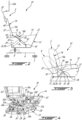
- the seat 10 generally includes a seat pan frame 14 supporting a seat pan 15, and a backrest frame 16 supporting a backrest 17. It is understood that the seat pan 15 and the backrest 17 may include any material suitable for providing appropriate support and comfort to the occupant, including, but not limited to, suitable cushioning materials which will not be further described herein.
- the seat 10 is selectively configurable between a sitting configuration S shown in full lines and a reclined configuration R shown in dotted lines. In the reclined configuration R, the backrest 17 may form an angle of 45 degrees with the vertical or horizontal, and the seat pan 15 may for an angle of 15 degrees with the horizontal.
- the reclined configuration R may be characterized as a deep recline configuration of the seat 10.
- a rear end of the seat pan 15 sinks downward by about 5 inches relative to a front end of the seat pan 15.
- the sitting configuration S also shown in Fig. 6a , corresponds to a taxi, take-off and landing (TTOL) configuration.
- the backrest frame 16 has an upper backrest member 16a supporting the backrest 17, and a lower backrest member 16b extending downwardly from a bottom end of the upper backrest member 16a.
- the upper and lower backrest members 16a, 16b are pivotally interconnected by a selectively lockable pivot connection 18, e.g. a selectively lockable revolute joint.
- a selectively lockable pivot connection 18 e.g. a selectively lockable revolute joint.
- the term "revolute joint” is intended to designate a pivot connection between two members which allows relative pivoting motion between the two members about an axis of rotation without allowing relative translation between the two members, i.e. the axis of rotation has a fixed location with respect to each of the two members.
- revolute joints include, but are not limited to, a hinge joint, a pin joint, and a folding joint.
- the pivot connection 18 between the upper and lower backrest members 16a, 16b has a locked configuration where a relative pivoting motion between the upper and lower backrest members 16a, 16b is prevented and an unlocked configuration where the relative pivoting motion between the upper and lower backrest members 16a, 16b is allowed.
- the pivot connection 18 may include, for example, a lock based on a spring-loaded plunger mechanism; any other suitable mechanism may alternately be used.
- the upper and lower backrest members 16a, 16b remain with a fixed relative orientation with respect to one another (i.e.
- the pivot connection 18 between the upper and lower backrest members 16a, 16b remains in the locked configuration) as the seat 10 is moved from the sitting configuration S to the reclined configuration R, and from the reclined configuration R to the sitting configuration S.
- the pivot connection 18 is only unlocked when the seat 10 is moved to a berth configuration B ( Fig. 6c ).
- the upper and lower backrest members 16a, 16b are non-parallel when in the locked configuration. It is understood that in an alternate embodiment, the upper and lower backrest members 16a, 16b may be rigidly interconnected.
- the backrest 17 also includes a headrest 20 which is slidingly engaged to a top or upper end of the upper backrest member 16a.
- the headrest 20 may include a pivotable portion 20a allowing for further adjustment of the position of the headrest 20. It is understood that the headrest configuration shown is exemplary only, and that any other suitable headrest configuration may alternately be used; alternately, the adjustable headrest 20 may be omitted.
- the front end of the seat pan frame 14 is connected to the front of the base 12 via a pivot connection 22, which in the embodiment shown is defined by a revolute joint or fixed pivot, i.e. a pivot having a fixed location on the base 12.
- the pivot connection 22 is vertically-stable, i.e., remains at a same height with the front end of the seat pan 15 relative to the floor structure 7 throughout the movement of the seat to and from any of the sitting, reclined and berth configurations S, R, B.
- the base 12 includes two laterally spaced interconnected base portions 12a; the front end of the seat pan frame 14 is received between the front ends of the base portions 12a and is pivotally connected thereto.
- the pivot connection 22 may be defined by a single pivot interconnecting the front end of the seat pan frame 14 to both base portions 12a, or by separate pivots interconnecting the front end of the seat pan frame 14 to each base portion 12a. Other configurations are also possible.
- the backrest frame 16 is connected to the base 12 by a support arm 24 and is free of direct connections with the base 12.
- the support arm 24 has one end connected to the base 12 via another pivot connection 26, which in the embodiment shown is also defined as a fixed pivot or revolute joint.
- the pivot connection 26 between the support arm 24 and the base 12 is located rearward of the pivot connection 22 between the front end of the seat pan frame 14 and the base 12 and, in the embodiment shown, is located at the rear of the base 12.
- the pivot connection 22 between the front end of the seat pan frame 14 and the base 12 is upwardly offset with respect to the pivot connection 26 between the support arm 24 and the base 12.
- the support arm 24 has an opposed end pivotally connected to the lower backrest member 16b by another pivot connection 28 defined at a location spaced from the upper backrest member 16a.
- the pivot connection 28 between the support arm 24 and the lower backrest member 16b is defined by another revolute joint.
- the support arm 24 includes two laterally spaced interconnected rods 24a
- the lower backrest member 16b includes two laterally spaced interconnected portions 16b'.
- the pivot connection 28 between the support arm 24 and the lower backrest member 16b is defined by separate pivots interconnecting the end of each of the lower backrest member portions 16b' to the end of a respective one of the rods 24a
- the pivot connection 26 between the support arm 24 and the base 12 is defined by separate pivots interconnecting the other end of each of the rods 24a to the base 12.
- Other configurations are also possible.
- the backrest frame 16 and seat pan frame 14 are also interconnected: the rear end of the seat pan frame 14 is pivotally connected to the lower backrest member 16b by another pivot connection 30 defined at a location between the upper backrest member 16a and the pivot connection 28 between the support arm 24 and the lower backrest member 16b.
- the pivot connection 30 between the lower backrest member 16b and the rear end of the seat pan frame 14 is defined by another revolute joint.
- the pivot connection 30 between the lower backrest member 16b and the seat pan frame 14 is defined by a single pivot interconnecting both lower backrest member portions 16b' to the rear end of the seat pan frame 14.
- Other configurations are also possible.
- the backrest frame 16 and seat pan frame 14 move simultaneously between the sitting configuration S and the reclined configuration R through pivoting motion about the four pivot connections 22, 26, 28, 30 defined between the seat pan frame 14 and the base 12, between the support arm 24 and the base 12, between the support arm 24 and the lower backrest member 16b, and between the lower backrest member 16b and the seat pan frame 14, while the upper and lower backrest members 16a, 16b remain at a fixed orientation with respect to one another, e.g. while the pivot connection 18 between the upper and lower backrest members 16a, 16b remains in the locked configuration.
- pivot connection 26 between the support arm 24 and the base 12 is located under the backrest frame 16, and the backrest frame 16 remains over this pivot connection 26 throughout the motion of backrest frame 16 and seat pan frame 14 between the sitting and reclined configurations S, R.
- the support arm 24 also remains under the backrest frame 16, and the two pivot connections 28, 30 of the lower backrest member 16b remain forward of and higher than the pivot connection 26 between the support arm 24 and the base 12 throughout this motion.
- an effective length d 1 of the support arm 24 defined by the distance between the two pivot connections 26, 28 of the support arm 24, an effective length d 2 of the lower backrest member 16b defined by the distance between the two pivot connections 28, 30 of the lower backrest member 16b, and an angle ⁇ between the upper and lower backrest members 16a, 16b when in the locked configuration are selected so that the variation in the angle of the backrest 17 has a linear relationship with respect to a variation in the angle of the seat pan 15 as the seat pan frame 14 and backrest frame 16 are moved between the sitting and reclined configurations S, R.
- Fig. 5 shows examples of the angle variation of the seat pan 15 in relation to the angle variation of the backrest 17 for different seat configurations, with lines M showing maximum targeted variations.
- Curve A shows a theoretical linear relationship
- curves B and C show relationships which are sufficiently close to the theoretical linear relationship A to be characterized as linear.
- curve B corresponds to the seat 10 of Figs. 2-4 where the effective length d1 of the support arm 24 is twice or about twice the effective length d2 of the lower backrest member 16b, and where the upper and lower backrest members 16a, 16b extend at an angle ⁇ of 135 degrees or about 135 degrees to each other in the locked configuration.
- the effective length d1 of the support arm 24 is about 1.875 times the effective length d2 of the lower backrest member 16b with the angle ⁇ being 135 degrees or about 135 degrees.
- the effective length d2 of the lower backrest member 16b is about 1 ⁇ 4 the length of the seat pan frame 14 as measured between its pivot connections 22, 30, and the effective length d1 of the support arm 24 is from 1.875 to 2 times the effective length d2 of the lower backrest member 16b with the angle ⁇ being 135 degrees or about 135 degrees.
- all these combinations of values are applicable for a seat pan depth of 16 inches, and a recline angle range of 5 to 15 degrees for the seat pan and 20 to 43 degrees for the backrest.
- curve D shows a relationship which is not linear; in a particular embodiment, this corresponds to a seat where the upper and lower backrest members 16a, 16b are parallel or approximately parallel, and where the effective length d1 of the support arm 24 is more than twice the effective length d2 of the lower backrest member 16b.
- the linear relationship between the variation in the angle of the seat pan 15 and the variation in the angle of the backrest 17 provides for a more stable motion between the sitting and reclined configurations S, R, which may be easier to operate and/or more comfortable for the occupant, then a seat where the relationship is not linear.
- the seat 10 further includes a biasing and/or damping member, for example a gas spring, an electrically-driven linear actuator or any other suitable type of linear actuator located under the seat pan frame 14, referred to henceforth as a seat pan linear actuator 32.
- a biasing and/or damping member for example a gas spring, an electrically-driven linear actuator or any other suitable type of linear actuator located under the seat pan frame 14, referred to henceforth as a seat pan linear actuator 32.
- the seat pan linear actuator 32 has a rear end pivotally connected to the lower backrest member 16b and to the rear end of the seat pan frame 14 at the pivot connection 30 between the lower backrest member 16b and the rear end of the seat pan frame 14.
- the lower backrest member 16b and the rear end of the seat pan frame 14 may be interconnected by a revolute joint defined by a rod 34, with the lower backrest member portions 16b' and the rear end of the seat pan frame 14 pivotally engaged to the rod 34 adjacent its ends, and the rear end of the seat pan linear actuator 32 pivotally engaged to a central portion of the rod 34.
- Other configurations are of course possible.
- the opposed, front end of the seat pan linear actuator 32 is pivotally connected to the base 12 by a pivot connection 36, which in the embodiment shown is also defined as a fixed pivot or revolute joint.
- the pivot connection 36 between the seat pan linear actuator 32 and the base 12 is located between the pivot connections 22, 26 of the base 12 with the front end of the seat pan frame 14 and with the support arm 24.
- the seat pan linear actuator 32 is positioned so that the movement of its rear end connected to the lower backrest member 16b and to the seat pan frame 14 is as close as possible to the axis of the seat pan linear actuator 32 so as to maximize the efficiency of the seat pan linear actuator 32.
- the seat pan linear actuator 32 is selected so that its stroke during the motion of the seat pan frame 14 and backrest frame 16 is at most 1/3 of the total extended length of the seat pan linear actuator 32; other values are also possible.
- the front end of the seat pan linear actuator 32 is connected toward the front of the base 12, so that its connection with the base 12 remains forward of its connection with the lower backrest member 16b and seat pan frame 14 throughout the motion of backrest frame 16 and seat pan frame 14 between the sitting and reclined configurations S, R. It can be seen from Fig. 3 that the pivot connections 28, 30 of the lower backrest member 16b remain rearward of the pivot connection 36 between the seat pan linear actuator 32 and the base 12 as the backrest frame 16 and seat pan frame 14 move between the sitting configuration S and the reclined configuration R.
- the pivot connection 22, the pivot connection 26 and the pivot connection 36 may be respectively referred to as a first fixed pivot 22, a second fixed pivot 26 and a third fixed pivot 36.
- Another linear actuator referred to as a backrest linear actuator 32' is attached toward the rear of the base 12.
- the backrest linear actuator 32' is a biasing and/or damping member, for example a gas spring, an electrically-driven linear actuator or any other suitable type of linear actuator.
- the backrest linear actuator 32' has an upper end pivotally connected to the upper backrest member 16a, and a lower end pivotally connected to the base 12 via a fourth fixed pivot 38 located rearward of the third fixed pivot 36, at a location closer to the second fixed pivot 26 than to the third fixed pivot 36.
- the fourth fixed pivot 38 is also a revolute joint.
- the second fixed pivot 26 and the fourth fixed pivot 38 are coaxial, such that the rear end of the support arm 24 and the lower end of the backrest linear actuator 32' are pivotable about a same axis.
- the upper end of the backrest linear actuator 32' connects to the upper backrest member 16a via a pivot connection 40 that is centrally-located, i.e., located closer to a longitudinal center of the upper backrest member 16a than to either ends thereof. Stated otherwise, the backrest linear actuator 32' connects to the upper backrest member 16a at a generally intermediate location between the headrest 20 and the lower backrest member 16b.
- the pivot connection 40 is also a revolute joint.
- a length L' ( Fig. 7c ) of the backrest linear actuator 32' defined between the upper end and the lower end thereof is greater in the sitting configuration S than in the reclined configuration R.
- the length L' of the backrest linear actuator 32' is at its maximum value.
- the length L' of the backrest linear actuator 32' is minimal. Stated otherwise, the backrest linear actuator 32' is fully extended in the sitting configuration S and fully compressed in the reclined configuration R. Conversely, it can be observed that a length L' ( Fig. 7c ) of the seat pan linear actuator 32 defined between the front and rear ends thereof is greater in the sitting configuration S than in the reclined configuration R.
- the length L' of the seat pan linear actuator 32 is minimal, i.e., the seat pan linear actuator 32 is fully compressed. As the seat 10 moves between the sitting configuration S and the reclined configuration R, the upper end of the backrest linear actuator 32' remains over the base 12.
- the seat 10 also has an upright configuration U ( Fig. 6b ), where the backrest 17 is closer to the vertical (more upright) than in the sitting configuration S ( Fig. 6a ) and/or where the seat pan frame 14 is horizontal or approximately horizontal.
- the seat pan frame 14 and backrest frame 16 move simultaneously between the sitting configuration S ( Fig. 6a ) and the upright configuration U ( Fig.
- the seat 10 also has a berth configuration B ( Fig. 6c ), where the backrest 17 and seat pan 15 are aligned or approximately aligned, for example horizontally so that the seat 10 may serve as a bed.
- the upper end of the backrest linear actuator 32' is located rearward of the base 12, over the floor structure 7.
- the seat 10 is configured between the upright configuration U and the berth configuration B by unlocking the pivot connection 18 between the upper and lower backrest members 16a, 16b, and pivoting the upper backrest member 16a rearwardly with respect to the lower backrest member 16b about the unlocked pivot connection 18.
- the position of the support arm 24, seat pan frame 14 and lower backrest member 16b is the same between the upright configuration U ( Fig. 6b ) and the berth configuration B ( Fig. 6c ), i.e. the seat 10 is configured between the upright configuration U and the berth configuration B without any pivoting motion about the four pivot connections 22, 26, 28, 30 defined between the seat pan frame 14 and the base 12, between the support arm 24 and the base 12, between the support arm 24 and the lower backrest member 16b, and between the lower backrest member 16b and the seat pan frame 14.
- the seat 10 can be displaced directly to the berth configuration B by starting from any position between the sitting configuration S and the reclined configuration R, without having to transition first to either one of the sitting configuration S and the upright configuration U. In such a displacement of the seat 10, suitable pivoting motion about the four pivot connections 22, 26, 28, 30 may occur.
- the length L of the seat pan linear actuator 32 is maximized, i.e., fully extended.
- the length L' of the backrest linear actuator 32' is minimized, i.e., fully compressed.
- the length L' of the backrest linear actuator 32' is substantially the same in the reclined configuration R ( Fig. 3 ) and in the berth configuration B ( Fig. 6c ).
- the backrest linear actuator 32' follows and supports the upper backrest member 16a, functioning as a load-bearing member and a fulcrum for the upper backrest member 16a to pivot thereabout.
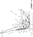
- a seat 110 in accordance with another embodiment is shown, where elements similar to the corresponding elements of the seat 10 of Figs. 2-4 and 6a-6c are identified by the same reference numerals and will not be further described herein.
- the seat 110 is shown in the sitting ( Fig. 7a ), reclined ( Fig. 7b ) and berth ( Fig. 7c ) configurations S, R, B.
- the individual positions of the seat pan frame 14, the upper backrest member 16a, the lower backrest member 16b and the support member 24 are different in each of the sitting, reclined and berth configurations S, R, B, and vary as the seat 10, 110 transitions therebetween.
- the seat 10, 110 moves from the reclined configuration R ( Fig. 7b ) to the berth configuration B ( Fig. 7c )
- the upper end and the lower end of the upper backrest member 16a respectively pivot downwardly and upwardly relative to the pivot connection 40.
- Urging the upper end of the upper backrest member 16a to pivot downwardly causes the lower backrest member 16b and the pivot connection 30 at the rear end of the seat pan frame 14 to move upwardly, thereby pivoting the seat pan frame 14 about the first fixed pivot 22 toward a horizontal orientation ( Fig. 7c ).
- the upward pivoting of the rear end of the seat pan frame 14 and the downward pivoting of the upper end of the upper backrest member 16a are further aided by the seat pan linear actuator 32 pushing against the rear end of the seat pan frame 14 as the seat pan linear actuator 32 extends to its fully extended length L in the berth configuration B.
- the seat pan linear actuator 32 remains forward of the backrest linear actuator 32', whereas the backrest linear actuator 32' remains rearward of the seat pan frame 14.
- the dynamics of the seat 10, 100 moving to and fro any of the sitting, reclined and berth configurations S, R, B are controlled by the seat pan linear actuator 32 and the backrest linear actuator 32', exerting either impulsion or damping as the case may be.
- the linear actuators 32, 32' are selectively lockable so as to bind the seat 10 in any given configuration, for example in transitory configurations other than the sitting, reclined and berth configurations S, R, B.
- One such transitory configuration is a neutral configuration (not shown), in which the pivot connection 18 is unlocked and both linear actuators 32, 32' are fully extended, such that the seat pan 15 is horizontal and the backrest 17 is at approximately 45 degrees from the vertical.
- the seat 10, 110 can be rotated about the pivot 8 ( Fig. 2 ) so as to face an adjacent seat to be used as an ottoman or as a bed extension.
- the rear end of the seat pan linear actuator 32 connects to the seat pan frame 14 at a pivot connection 30' ( Figs. 7a , 7c ) located rearward of the pivot connection 30.
- the pivot connection 40 via which the upper end of the backrest linear actuator 32' connects to the upper backrest member 16a, is located closer to the headrest 20 than to the lower backrest member 16b.
- the fourth fixed pivot 38 via which the lower end of the backrest linear actuator 32' connects to the base 12, is located rearward and upward of the second fixed pivot 26.
- the seat 110 further includes a pair of linear actuators referred to as side linear actuators 32" disposed on either side of the backrest frame 16.
- each one of the side linear actuators 32" is a biasing and/or damping members, for example a gas spring, an electrically-driven linear actuator or any other suitable type of linear actuator.
- Each side linear actuator 32" has an upper end pivotally connected to the upper backrest member 16a via a pivot connection 42, and a lower end pivotally connected to the lower backrest member 16b via a pivot connection 44 located rearward of the pivot connection 18.
- the pivot connections 42, 44 are revolute joints. It shall be noted that a length L" ( Fig.
- each side linear actuator 32" defined between its upper and lower ends is longest in the sitting configuration S and shortest in the berth configuration B. Stated otherwise, the length L" of each side linear actuator 32" shortens, or compresses, as the seat 110 moves from the sitting configuration S to the reclined configuration R, and shortens, or compresses, further as the seat 110 moves from the reclined configuration R to the berth configuration B. Upon being in a compressed state, each side linear actuator 32" exerts opposed forces at either of its upper and lower ends, pushing upward against the upper backrest member 16a and pushing downward against the lower backrest member 16b.
- each side linear actuator 32" urges the upper backrest member 16a to pivot forwardly and upwardly relative to the pivot connection 18, and simultaneously urges the lower backrest member 16b to pivot downwardly relative to the pivot connection 22 with the seat pan frame 14. This may help to position the seat 110 in a sitting configuration S or even an upright configuration in situations where the passenger gets up from the seat 110 while it is in the reclined or berthed configurations R,B, and while the pivot connection 18 is unlocked.
- reclining the seat 10, 110 includes changing the angle of the seat pan 15 and the angle of the backrest 17 by simultaneously pivoting the front end of the seat pan 15 about a first fixed location defined by the pivot connection 22 between the seat pan frame 14 and the base 12, pivoting the support arm 24 about a second fixed location defined by the pivot connection 26 between the support arm 24 and the base 12 and which is located aft of the first fixed location 22, pivoting the backrest 17 relative to the support arm 24 about a third location defined by the pivot connection 28 between the support arm 24 and the lower backrest member 16b, pivoting the backrest 17 relative to the rear end of the seat pan 15 about a fourth location defined by the pivot connection 30 between the seat pan frame 14 and the lower backrest member 16b, and pivoting the backrest 17 relative to the upper end of the backrest linear actuator 32' about a fifth location defined by the pivot connection 40 on the upper backrest member 16a, causing the lower end of the backrest linear actuator 32' to
- pivoting the backrest 17 relative to the upper end of the backrest linear actuator 32' causes the length L' of the backrest linear actuator 32' defined between the upper end and the lower end of the backrest linear actuator 32' to be minimized as the backrest 17 pivots from the sitting configuration S toward the berth configuration B before the backrest 17 reaches the berth configuration B.
- the length L' of the backrest linear actuator 32' is maintained, or remains unchanged, as the backrest 17 is pivoted from the berth configuration B to the reclined configuration R.
- pivoting the backrest 17 relative to the upper end of the backrest linear actuator 32' causes the length L' of the backrest linear actuator 32' to be minimized as the backrest 17 is pivoted from the sitting configuration S toward the reclined configuration R.
- the length L' of the backrest linear actuator 32' is maintained as the backrest 17 is pivoted from the reclined configuration R to the berth configuration B.
- pivoting the backrest 17 from the reclined configuration R to the berth configuration B causes the upper end of the backrest linear actuator 32' to be displaced rearwardly relative to the lower end of the backrest linear actuator 32'.
- reclining the seat 10, 110 further includes pivoting the backrest 17 to the sitting configuration S from any one of the reclined configuration R and the berth configuration B upon the aircraft 1 being in one or more of the taxi, take-off or landing phases.
- the configuration of the pivot connections 22, 26, 28, 30 allows for the motion of the seat 10, 110 to be easier and/or more comfortable when compared to a similar seat having one or more sliding mechanism(s) involved in the motion of the seat.
- the configuration of the pivot connections 22, 26, 28, 30 allows for a range of motion for the seat 10, 110 similar to that of a seat having one or more sliding mechanism(s).
Landscapes
- Engineering & Computer Science (AREA)
- Aviation & Aerospace Engineering (AREA)
- Transportation (AREA)
- Mechanical Engineering (AREA)
- Chairs For Special Purposes, Such As Reclining Chairs (AREA)
Applications Claiming Priority (1)
| Application Number | Priority Date | Filing Date | Title |
|---|---|---|---|
| US202163253771P | 2021-10-08 | 2021-10-08 |
Publications (1)
| Publication Number | Publication Date |
|---|---|
| EP4163150A1 true EP4163150A1 (fr) | 2023-04-12 |
Family
ID=85463142
Family Applications (1)
| Application Number | Title | Priority Date | Filing Date |
|---|---|---|---|
| EP22200293.3A Pending EP4163150A1 (fr) | 2021-10-08 | 2022-10-07 | Siège inclinable à configurations multiples |
Country Status (4)
| Country | Link |
|---|---|
| US (1) | US12054079B2 (fr) |
| EP (1) | EP4163150A1 (fr) |
| CN (1) | CN115959290A (fr) |
| CA (1) | CA3178812A1 (fr) |
Families Citing this family (1)
| Publication number | Priority date | Publication date | Assignee | Title |
|---|---|---|---|---|
| US20250242921A1 (en) * | 2024-01-25 | 2025-07-31 | B/E Aerospace, Inc. | Lock spring damper system |
Citations (2)
| Publication number | Priority date | Publication date | Assignee | Title |
|---|---|---|---|---|
| US20190308579A1 (en) * | 2018-04-06 | 2019-10-10 | Astronics Advanced Electronic Systems Corp. | Seat Sensing and Reporting Apparatus |
| EP3728033A1 (fr) * | 2017-12-21 | 2020-10-28 | Bombardier Inc. | Siège passager inclinable |
Family Cites Families (30)
| Publication number | Priority date | Publication date | Assignee | Title |
|---|---|---|---|---|
| US2073872A (en) | 1933-08-28 | 1937-03-16 | Steel Wheel Corp | Vehicle |
| US3540777A (en) | 1967-12-02 | 1970-11-17 | Mario Revelli De Beaumont | Chair for automotive vehicles with a displaceable back |
| US3622202A (en) | 1969-07-07 | 1971-11-23 | Vernon C Brown | Adjustable chair and control therefor |
| US3819229A (en) | 1970-11-05 | 1974-06-25 | Lane Co Inc | Rocker recliner chair |
| JP2601366Y2 (ja) | 1992-02-28 | 1999-11-15 | 小糸工業株式会社 | シートバックの前方への傾斜ロック構造 |
| JPH0582337U (ja) | 1992-04-13 | 1993-11-09 | アラコ株式会社 | シートのフルフラット機構 |
| JP3325112B2 (ja) | 1994-03-11 | 2002-09-17 | 天龍工業株式会社 | 乗物用座席 |
| DE19639741C2 (de) | 1996-09-06 | 1998-07-09 | Thomas Jungjohann | Sitzmöbelelement, insbesondere Polstermöbelelement, mit einer gekoppelten Rückenlehnen- und Sitzverstellung |
| NO312491B1 (no) | 1997-02-28 | 2002-05-21 | Kjartan Alvestad | Reguleringsanordning for understöttelsesrammen i ligge- eller sittemöbel |
| JP2000085424A (ja) | 1998-09-14 | 2000-03-28 | Koito Ind Ltd | 車両用シート |
| DE60117923T2 (de) | 2000-01-14 | 2006-09-14 | BE Aerospace, Inc., Wellington | Fahrgastsitz mit variabler Sitzfläche |
| DE10106792A1 (de) | 2001-02-12 | 2002-08-14 | Interstuhl Bueromoebel Gmbh | Sitzmöbel |
| FR2840282B1 (fr) | 2002-05-31 | 2004-07-30 | Sicma Aero Seat | Siege transformable en couchette a accoudoir deformable |
| EP2010027A2 (fr) | 2006-04-27 | 2009-01-07 | Vitra Patente AG | Mecanisme pour une chaise |
| DE102007001962A1 (de) | 2007-01-13 | 2008-07-17 | Recaro Aircraft Seating Gmbh & Co. Kg | Sitzvorrichtung |
| GB0706775D0 (en) | 2007-04-05 | 2007-05-16 | Premium Aircraft Interiors Uk | Aircraft seat |
| DE102010033752B4 (de) | 2010-08-07 | 2020-04-09 | Recaro Aircraft Seating Gmbh & Co. Kg | Fahrzeugsitz, insbesondere Fluggastsitz |
| US10293942B2 (en) | 2010-10-15 | 2019-05-21 | Bombardier Inc. | Aircraft interior configuration |
| US9714862B2 (en) | 2011-10-07 | 2017-07-25 | Bombardier Inc. | Aircraft seat |
| US9592914B2 (en) | 2011-10-07 | 2017-03-14 | Bombardier Inc. | Aircraft seat |
| US9714095B2 (en) | 2011-10-07 | 2017-07-25 | Bombardier Inc. | Aircraft seat |
| US9073453B2 (en) | 2011-10-07 | 2015-07-07 | Bombardier Inc. | Aircraft seat |
| JP2015012909A (ja) | 2013-07-03 | 2015-01-22 | コイト電工株式会社 | 座席装置 |
| CN110254726B (zh) | 2013-12-27 | 2023-02-28 | 庞巴迪公司 | 长沙发椅 |
| US20160325837A1 (en) | 2013-12-30 | 2016-11-10 | Bombardier Inc. | Aircraft seat |
| JP5827715B2 (ja) | 2014-03-14 | 2015-12-02 | 株式会社ジャムコ | 航空機の乗客用シ−トのベッドモード機構 |
| US10583926B2 (en) | 2014-09-25 | 2020-03-10 | Bombardier Inc. | Aircraft seat |
| FR3042172B1 (fr) | 2015-10-13 | 2017-11-24 | Airbus Operations Sas | Siege reglable |
| EP3222523B1 (fr) | 2016-03-23 | 2019-09-11 | Airbus Operations GmbH | Banquette de siège pliable |
| EP3519243B1 (fr) * | 2016-09-28 | 2022-08-17 | Rockwell Collins, Inc. | Ensemble de siège passager d'aéronef comprenant un appareil d'inclinaison de dossier |
-
2022
- 2022-10-07 EP EP22200293.3A patent/EP4163150A1/fr active Pending
- 2022-10-07 US US17/961,659 patent/US12054079B2/en active Active
- 2022-10-07 CA CA3178812A patent/CA3178812A1/fr active Pending
- 2022-10-08 CN CN202211221372.8A patent/CN115959290A/zh active Pending
Patent Citations (2)
| Publication number | Priority date | Publication date | Assignee | Title |
|---|---|---|---|---|
| EP3728033A1 (fr) * | 2017-12-21 | 2020-10-28 | Bombardier Inc. | Siège passager inclinable |
| US20190308579A1 (en) * | 2018-04-06 | 2019-10-10 | Astronics Advanced Electronic Systems Corp. | Seat Sensing and Reporting Apparatus |
Also Published As
| Publication number | Publication date |
|---|---|
| US12054079B2 (en) | 2024-08-06 |
| US20230111420A1 (en) | 2023-04-13 |
| CN115959290A (zh) | 2023-04-14 |
| CA3178812A1 (fr) | 2023-04-08 |
Similar Documents
| Publication | Publication Date | Title |
|---|---|---|
| US11685532B2 (en) | Reclinable passenger seat | |
| US8579375B2 (en) | Aircraft seat | |
| CN105163628B (zh) | 具有椅盘和椅背的联动接合部的交通工具座椅 | |
| US20180086468A1 (en) | Aircraft Passenger Seat Assembly Including a Backrest Tilt Apparatus | |
| US20160325837A1 (en) | Aircraft seat | |
| EP3971027B1 (fr) | Siège réglable | |
| CN111572780B (zh) | 多位置可调节头枕组件 | |
| CA2904875A1 (fr) | Siege d'aeronef ayant un pivot de liaison de dossier mobile en translation | |
| EP4037971B1 (fr) | Mécanisme cinématique et d'inclinaison à intrusion nulle pour sièges d'avion commerciaux | |
| EP4163150A1 (fr) | Siège inclinable à configurations multiples | |
| US11447254B2 (en) | Passenger seat with support structure including offset struts | |
| EP3728032B1 (fr) | Siège passager doté d'une structure de support définissant un espace vide | |
| CA3101133C (fr) | Siège passager doté d’une structure de support incluant des montants décalés | |
| CA3086354C (fr) | Siege passager dote d'une structure de support definissant un espace vide | |
| CN112591103A (zh) | 飞行器沙发椅 | |
| US11254434B2 (en) | Headrest for a seat |
Legal Events
| Date | Code | Title | Description |
|---|---|---|---|
| PUAI | Public reference made under article 153(3) epc to a published international application that has entered the european phase |
Free format text: ORIGINAL CODE: 0009012 |
|
| STAA | Information on the status of an ep patent application or granted ep patent |
Free format text: STATUS: REQUEST FOR EXAMINATION WAS MADE |
|
| 17P | Request for examination filed |
Effective date: 20221007 |
|
| AK | Designated contracting states |
Kind code of ref document: A1 Designated state(s): AL AT BE BG CH CY CZ DE DK EE ES FI FR GB GR HR HU IE IS IT LI LT LU LV MC ME MK MT NL NO PL PT RO RS SE SI SK SM TR |
|
| P01 | Opt-out of the competence of the unified patent court (upc) registered |
Effective date: 20230526 |