EP4163219B1 - Kindersicherer behälter und verfahren zu seiner herstellung - Google Patents
Kindersicherer behälter und verfahren zu seiner herstellung Download PDFInfo
- Publication number
- EP4163219B1 EP4163219B1 EP22198509.6A EP22198509A EP4163219B1 EP 4163219 B1 EP4163219 B1 EP 4163219B1 EP 22198509 A EP22198509 A EP 22198509A EP 4163219 B1 EP4163219 B1 EP 4163219B1
- Authority
- EP
- European Patent Office
- Prior art keywords
- tab
- coupling portion
- panel
- spacer
- operative position
- Prior art date
- Legal status (The legal status is an assumption and is not a legal conclusion. Google has not performed a legal analysis and makes no representation as to the accuracy of the status listed.)
- Active
Links
Images


Classifications
-
- B—PERFORMING OPERATIONS; TRANSPORTING
- B65—CONVEYING; PACKING; STORING; HANDLING THIN OR FILAMENTARY MATERIAL
- B65D—CONTAINERS FOR STORAGE OR TRANSPORT OF ARTICLES OR MATERIALS, e.g. BAGS, BARRELS, BOTTLES, BOXES, CANS, CARTONS, CRATES, DRUMS, JARS, TANKS, HOPPERS, FORWARDING CONTAINERS; ACCESSORIES, CLOSURES, OR FITTINGS THEREFOR; PACKAGING ELEMENTS; PACKAGES
- B65D5/00—Rigid or semi-rigid containers of polygonal cross-section, e.g. boxes, cartons or trays, formed by folding or erecting one or more blanks made of paper
- B65D5/38—Drawer-and-shell type containers
-
- B—PERFORMING OPERATIONS; TRANSPORTING
- B65—CONVEYING; PACKING; STORING; HANDLING THIN OR FILAMENTARY MATERIAL
- B65D—CONTAINERS FOR STORAGE OR TRANSPORT OF ARTICLES OR MATERIALS, e.g. BAGS, BARRELS, BOTTLES, BOXES, CANS, CARTONS, CRATES, DRUMS, JARS, TANKS, HOPPERS, FORWARDING CONTAINERS; ACCESSORIES, CLOSURES, OR FITTINGS THEREFOR; PACKAGING ELEMENTS; PACKAGES
- B65D5/00—Rigid or semi-rigid containers of polygonal cross-section, e.g. boxes, cartons or trays, formed by folding or erecting one or more blanks made of paper
- B65D5/42—Details of containers or of foldable or erectable container blanks
- B65D5/64—Lids
- B65D5/66—Hinged lids
- B65D5/6626—Hinged lids formed by folding extensions of a side panel of a container body formed by erecting a "cross-like" blank
- B65D5/665—Hinged lids formed by folding extensions of a side panel of a container body formed by erecting a "cross-like" blank the lid being held in closed position by self-locking integral flaps or tabs
-
- B—PERFORMING OPERATIONS; TRANSPORTING
- B65—CONVEYING; PACKING; STORING; HANDLING THIN OR FILAMENTARY MATERIAL
- B65D—CONTAINERS FOR STORAGE OR TRANSPORT OF ARTICLES OR MATERIALS, e.g. BAGS, BARRELS, BOTTLES, BOXES, CANS, CARTONS, CRATES, DRUMS, JARS, TANKS, HOPPERS, FORWARDING CONTAINERS; ACCESSORIES, CLOSURES, OR FITTINGS THEREFOR; PACKAGING ELEMENTS; PACKAGES
- B65D5/00—Rigid or semi-rigid containers of polygonal cross-section, e.g. boxes, cartons or trays, formed by folding or erecting one or more blanks made of paper
- B65D5/42—Details of containers or of foldable or erectable container blanks
- B65D5/64—Lids
- B65D5/68—Telescope flanged lids
- B65D5/685—Telescope flanged lids having an inwardly or upwardly extending tab on the lid side wall cooperating with a tab on, or an opening in, the container side wall
-
- B—PERFORMING OPERATIONS; TRANSPORTING
- B65—CONVEYING; PACKING; STORING; HANDLING THIN OR FILAMENTARY MATERIAL
- B65D—CONTAINERS FOR STORAGE OR TRANSPORT OF ARTICLES OR MATERIALS, e.g. BAGS, BARRELS, BOTTLES, BOXES, CANS, CARTONS, CRATES, DRUMS, JARS, TANKS, HOPPERS, FORWARDING CONTAINERS; ACCESSORIES, CLOSURES, OR FITTINGS THEREFOR; PACKAGING ELEMENTS; PACKAGES
- B65D2215/00—Child-proof means
- B65D2215/02—Child-proof means requiring the combination of simultaneous actions
Definitions
- the object of the present invention is a child-proof container and a process for making the same.
- the container may be employed for packaging drug products, cosmetics, cleaning products (detergents for linen and dishware), foods and tobacco-based products (cigars and cigarettes).
- Packages made of paper material are known which are designed for being difficult for children to open for preventing these from coming into contact with products that are potentially damaging for them.
- a first type of child-proof package is described in the following documents: WO2021/044266A1 ; US2005/0173291A1 ; EP2808265A1 ; US6,491,211B1 ; WO2005/068304A2 ; US2014/262839A1 ; EP2810885A1 ; US2012/234701A1 ; CN204642380U ; WO2012/112538A1 ; WO2009/038219A1 ; US1,253,489A ; US1,130,271 .
- Such packages have a locking system which allows maintaining the same in a closed condition; the packages are openable due to the presence of a through access defined on a lateral wall of the package which allows a user to act, from outside the package, on the locking system.
- a second type of package is described in the US patent No. US 9,475,605B2 .
- Such package comprises a tray insertable in a casing; the tray has, at a top opening, two external locking tabs engageable in two respective lateral through openings of the casing in order to lock the package in a closed condition.
- a third package example is described in the French patent application No. FR783262A .
- Such package comprises a container having a top opening at which coupling tabs folded outside the package are present.
- the package is closeable by means of a lid having respective coupling portions suitable for being engaged with the folded tabs of the container for locking the package in the closed condition.
- a fourth package example is described in the application of US patent No. 2,559,320 .
- Such package comprises a container having a top opening at which folded external edges are present; on each edge, a rectangular notch is present from which a further tab is obtained, folded above the respective edge.
- the notch defines an opening suitable for receiving in engagement a respective tab carried by a lid of the package; the engagement of the tab of the lid with the external edge of the container allows locking the package in a closed condition.
- the package is openable by inserting a finger below the lid, forcing the tab of the lid to exit from the notch defined on the folded edge of the container.
- the product it is intended an article or a compound of articles of any kind.
- the product may also be intended as a package, e.g. a blister, carrying a plurality of articles.
- the product may comprise: drugs, cosmetic products, capsules for dishwashers and washing machines, products for cleaning the home and linen (e.g. detergents), foods and cigarettes.
- paper material it is intended paper or cardboard, optionally having at least 50% by weight, optionally at least 70% by weight, of organic material comprising one or more from among cellulose, hemicellulose, lignin, lignin derivatives.
- the paper material may be made of sheet material having a basis weight comprised between 100 g/m 2 and 500 g/m 2 .
- the paper material in question extends between a first and a second main extension surface.
- the paper sheet material employed for making the container may, in one embodiment variant thereof, be covered for at least one part of the first and/or second main extension surface by means of a plastic material covering, e.g. biodegradable.
- the covering In the event in which the covering is arranged so as to at least partly cover the first main extension surface, the same covering will come to define an internal surface of the container. On the other hand, in the event in which the covering is arranged on the second main extension surface, the same covering will come to define an external surface of the container.
- the covering may also be employed to define a kind of water and/or moisture barrier useful for preventing the weakening and the loss of structure of the constituent paper material.
- the covering may be applied to the paper material (as specified above on the internal and/or external side of the support) in the form of a so-called " coating " or lacquer deposited as a solution or sprayed whose thickness is generally comprised, in a non-limiting manner, between 0.2 ⁇ m and 10 ⁇ m.
- the covering may comprise a plastic film, for example a polyethylene coating, applicable by means of a rolling process, on one or both sides (internal and/or external side) of the paper material defining the container.
- the values of the plastic film (covering) may for example vary between 10 ⁇ m and 400 ⁇ m, in particular between 10 ⁇ m and 200 ⁇ m, still more in particular between 10 ⁇ m and 80 ⁇ m, of covering material (i.e. polythene).
- the plastic covering material may be selected, by way of example, from among the following materials: PP, PE (HDPE, LDPE, MDPE, LLDPE), EVA, polyesters (including PET and PETg), PVdC.
- blade refers to a flat semi-finished product made of sheet material, e.g. made of paper sheet material, foldable on itself for making the wall and/or the package.
- the blank may be made of a single piece and obtainable by means of die cutting of a single sheet.
- sheet material it is intended a material that has two dimensions, e.g. length and width, considerably greater than a third dimension, such as for example the thickness.
- panel it is intended a laminar body of monolithic type having a substantially constant thickness which may be constituted by a single panel (mono-layer) of sheet material or by a multi-layer defined by a plurality of mono-layer sheets coupled together in thickness.
- the panel may, in a non-limiting manner, be extended flatwise or follow a progression that is at least partly undulated.
- the opening device may comprise at least one selected from the following group: a body made of sheet material (e.g. a payment card, a loyalty card or a suitable key), an elongated body (e.g. a pen or a suitable key).
- a body made of sheet material e.g. a payment card, a loyalty card or a suitable key
- an elongated body e.g. a pen or a suitable key
- Reference number 1 overall indicates a container usable in the field of packaging for products of various type, for example drug products, cosmetics, cleaning products (detergents for linen and dishware), foods and tobacco-based products (cigars and cigarettes).
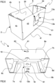
- the container 1 comprises a storage 2 ( figure 5 ) made of sheet material, for example paper material, defining a compartment 3 for housing products.
- the storage 2 comprises at least one lateral wall 4 defining at least one passage opening delimited by a free edge 6.
- the storage 2 may have a substantially prismatic shape, e.g. rectangular prismatic (it is possible to make a storage 2 having different shape, e.g. having square section, with a trapezium or cylindrical shape).
- the storage 2 may comprise a front wall 4a and a rear wall 4b facing and parallel to each other: the front wall 4a and the rear wall 4b are connected to each other by means of a first and a second lateral wall 4c, 4d, also facing and parallel to each other.
- the front wall 4a is spaced and opposite the rear wall 4b; the first and second lateral walls 4c, 4d are also spaced and opposite from each other.
- the front, rear and lateral walls (4a, 4b, 4c, 4d) define the passage opening, delimited by the free edge 6.
- the storage 2 also comprises a bottom wall 4f from which the following emerge, starting from a perimeter edge of the bottom wall 4f itself: the front wall 4a, the rear wall 4b and the first and second lateral walls 4c, 4d.
- the storage 2 thus comprises a single passage opening defined opposite the bottom wall 4f.
- the front wall 4a, the rear wall 4b, the first lateral wall 4c and the second lateral wall 4d delimit the compartment 3.
- the front wall 4a, the rear wall 4b, the first lateral wall 4c and the second lateral wall 4d emerge starting from the bottom wall 4f for a predetermined extension: such extension defines the height of the storage 2 which may be greater than 30 mm, optionally greater than 50 mm, still more optionally greater than 60 mm.
- the compartment 3 may have a volume greater than 40 cm 3 , optionally greater than 100 cm 3 as a function of the products to be contained. For example, in the event in which the container 1 is used for containing average-sized products, the compartment 3 may have a volume comprised between 800 and 1.400 cm 3 . For large-sized products, the volume of the compartment 3 may reach 10,000 cm 3 .
- the lateral wall 4 of the storage 2 (optionally at least one of said walls 4a-4d) comprises a flat panel 41 emerging from the bottom wall 4f and at least partly delimiting the compartment 3.
- at least one of said walls 4a-4d may be constituted by a single panel, i.e. by a single sheet of paper material.
- at least one of said walls 4a-4d of the storage 2 may comprise a first panel 41 and a second panel 42 facing and engaged with each other.
- the first and second panels 41, 42 may be integrally joined at a folding edge 6a ( figures 2 , 3 , 9 , 10 , 13 , 14 , 16 and 17 ) to define a folded portion; the first and second panels 41, 42 are partly in contact and constrained with each other, for example by means of gluing.
- the first panel 41 defines at least one part of an internal surface delimiting a part of the compartment 3 of the storage 2
- the second panel 42 defines at least one part of an external surface of the storage 2, opposite an internal surface delimiting the compartment 3 of the storage 2.
- each wall 4a-4d may have the configuration with internal panel (first panel 41) and external panel (second panel 42) described above. Illustrated in figures 2 , 3 , 9 , 10 , 13 , 14 , 16 and 17 is, in a non-limiting manner, a lateral wall 4 comprising said first and second panels 41, 42; nevertheless it is possible that each lateral wall 4a, 4b, 4c 4d have the first and second panels 41, 42.
- the storage 2 may be substantially identical to the container of the package as described in the patent application PCT No. WO 2021/044266 A1 from page 14, line 26, to page 15, line 7.
- the container 1 may comprise a closure system 7 made of sheet material, optionally paper, configured for essentially defining an element for closing the storage 2.
- the closure system 7 is movable, at least partly, relative to the storage 2 at least between:
- closure system 7 and the storage 2 are, in a non-limiting manner, elements that are distinct and completely separable from each other.
- closure system 7 and storage 2 are relatively movable with respect to each other at least between:
- the closure system 7 comprises a predetermined number of lateral walls defining at least one access delimited by a free edge 7b configured for allowing the passage of the storage 2.
- the predetermined number of lateral walls of the closure system 7 emerges from a top wall 7a which delimits, in cooperation with said lateral walls, an internal volume 7f configured for receiving at least part of the storage 2; actually, the access is configured for placing the internal volume 7f in communication with the outside environment, as well as to allow the insertion and the removal of the storage 2 from said internal volume 7f.
- the relative movement between closure system 7 and storage 2 may be obtained by moving both parts, i.e. both the closure system 7 and the storage 2 or it may be obtained by means of the movement of only one of the parts.
- the storage 2, in the closed condition (schematized for example in figures 4 and 11 ), is arranged at least partly in the internal volume 7f: the closure system 7, in such condition, prevents the insertion and the pick-up of products from the storage 2.
- the closure system 7 In the open condition, the closure system 7 is completely separated (spaced) from the storage 2 as is visible for example in figure 7 .
- storage 2 and closure system 7 slide relative to each other close to or away from each other: during such relative movement, the bottom wall 4f of the storage 2 and the top walls 7a of the closure system 7 are moved close to or away from each other.
- the closure system 7 has a size slightly greater than the storage 2, sufficient for allowing the insertion of the storage in the internal volume 7f.
- the closure system 7 has a structure at least partly countershaped with respect to the storage 2 in a manner such that, in the closed condition, the closure system 7 is fit outside the storage 2.
- the closure system 7 comprises a front wall 8a and a rear wall 8b opposite each other and connected by means of a first and a second lateral wall 8c and 8d, also spaced and opposite each other.
- the closure system 7 has a rectangular prismatic shape: the front wall 8a and the rear wall 8b (with square or rectangular shape) are facing and parallel to each other and connected together by means of the first and of the second lateral wall 8c, 8d (with square or rectangular shape), also facing and parallel to each other.
- the closed condition :
- closure system 7 having different form, for example having a section with trapezium shape.
- the closure system 7 may be engaged with the free edge 6 of the storage and be movable via rotation relative to said free edge between the open condition and the closed condition.
- the closure system 7 comprises a predetermined number of lateral walls defining at least one access delimited by a free edge 7b configured for allowing the insertion of the storage 2.
- the predetermined number of lateral walls of the closure system 7 emerges from a top wall which delimits, in cooperation with said lateral walls, the internal volume of the closure system configured for receiving at least part of the storage 2.
- closure system 7 may be obtained by moving both parts, i.e. both the closure system 7 and the storage 2 or it may be obtained by means of the movement of only one of the parts.
- the closure system 7 may be substantially identical to the casing of the package as described in the patent application PCT No. WO 2021/044266 A1 from page 15, line 8, to page 16, line 17.
- the container 1 also comprises:
- the first and second coupling portions 12, 13 are configured for being engaged with each other in the closed condition to define a locking condition of the container in which the first and second coupling portions 12, 13 prevent the closure system 7 from passing from the closed condition to the open condition.
- the first coupling portion 12 shown in figure 6 , is carried by at least one lateral wall of the closure system 7.
- the first coupling portion 12 comprises at least one tab 12a defining an undercut delimited by at least one grip edge 12b: such edge 12b is placed in the internal volume 7f, distinct and spaced from the free edge 7b of the closure system, hence being interposed between the top wall 7a and the free edge 7b of the closure system 7.
- the first coupling portion 12 may be integrally joined with a lateral wall of the closure system by means of a folding edge to define a folded portion in the internal volume 7f of the same closure system.
- the first coupling portion 12 may comprise at least one tab 12a directly integrally joined with at least one lateral wall by means of a folding edge to define a folded portion.
- the tab 12a is made of a single piece with a lateral wall in a manner such that said tab 12a is at least partly overlapped and facing the lateral wall to which said tab 12a is directly connected (integrally joined).
- the folding edge which joins the tab 12a and the lateral wall defines at least part of the free edge 7b of the closure system 7. Even if the tab 12a is integrally joined with the lateral wall, only a part thereof defines the undercut suitable for cooperating with the second coupling portion 13.
- the grip edge 12b may have a shape at least partially countershaped with respect to the second coupling portion 13.
- the grip edge 12b of the tab 12a may be, at least for a section, tilted with respect to the free edge 7b of the access, optionally by an angle comprised between 20° and 80°, still more optionally by an angle comprised between 30° and 70°.
- the tab 12a extends along a plane and directly faces the lateral wall of the closure system 7 directly carrying the tab 12a.
- the tab 12a may be tilted with respect to the lateral wall directly carrying the tab 12a by an angle lower than 40°, optionally by an angle comprised between 1° and 30°. Such angle is measured between the surface of the tab 12a directly facing the lateral wall of the closure system 7 and the same lateral wall of the closure system 7 directly carrying (directly integrally joined) the tab 12a.
- the tab 12a may be substantially parallel to the lateral wall of the closure system 7 directly carrying said tab 12a. Indeed, the tab 12a of the first coupling portion 12 is entirely facing and overlapped to the lateral wall of the closure system 7 directly carrying the tab 12a.
- the first coupling portion 12 may comprise two tabs 12a spaced and facing each other (condition not illustrated).
- the tabs 12a may be engaged at the same lateral wall of the closure system 7 and be substantially identical to each other in shape and size: the two tabs 12a are symmetric to each other and have respective grip edges 12b facing each other.
- the grip edges 12b of the two tabs 12a are spaced from each other and entirely positioned in the internal volume 7f, spaced from the free edge 7b: the grip edges 12b of the two tabs 12a may thus define a substantially "V" shape whose concavity is directed on the opposite side with respect to the access of the closure system 7.
- the grip edges 12b are facing the lateral wall of the closure system directly carrying (directly integrally joined) the tab 12a, spaced both from the free edge 7b and from the top wall 7a.
- the first coupling portion 12 may be substantially identical to the first coupling portion of the package, as described in the patent application PCT No. WO 2021/044266 A1 from page 16, line 18, to page 18, line 4.
- the container may comprise at least one of:
- first coupling portion 12 is carried, in a non-limiting manner, by the front wall 8a ( figure 4 and 8 ) or by the rear wall 8b ( figure 6 ) of the closure system 7. It is also possible to arrange one or more first coupling portions 12 on the same lateral wall and/or at least one first coupling portion 12 for each lateral wall of the closure system 7.
- the first coupling portion 12 may be fixed with respect to the closure system 7 (condition illustrated in the enclosed figures) or it may be defined on a selector carried by the lateral wall but movable with respect to said lateral wall.
- the first coupling portion 12 may be identical to the first coupling portion of the package as described in the patent application PCT No. WO 2021/0442668 A1 from page 20, line 9, to page 21, line 2, as well as from page 22, line 7, to page 23, line 28.
- the closure system 7 may also comprise a depression 18 defined at the edge 7b; such depression is configured for allowing a user, in the closed condition of the container, to grip the storage 2.
- the container comprises at least one second coupling portion 13 configured for cooperating with one or more of the first coupling portions 12 to define the locking condition.
- the container may comprise a second coupling portion 13 for each first coupling portion 12.
- the second coupling portion 13 is carried by at least one lateral wall of the storage 2 and emerges outside the compartment 3 of the storage 2, distinct and spaced from the free edge 6. Indeed, the first and second coupling portions, in the locking condition, are engaged outside the compartment 3 of the storage 2 and inside the internal volume 7f of the closure system 7.
- the second coupling portion 13 comprises a respective tab 13a projecting from the panel 41 of the lateral wall of the storage 2 to define an undercut delimited by at least one grip edge 13b placed outside the compartment 3, distinct and spaced from the free edge 6 of the passage opening.
- the tab 13a may be joined by means of a folding edge to a lateral wall 4 of the storage to define a folded portion.
- the tab 13a may thus face and at least partly overlapped to the panel 41 of the lateral wall of the storage with which said tab 13a is directly integrally joined.
- the tab 13a is made directly on a lateral wall of the storage 2 by means of a through cut a lateral wall itself: the tab 13a thus defines at least part of the lateral wall of the storage 2 to which the same tab 13a is integrally joined.
- the tab 13a may thus be spaced from the free edge 6 of the storage 2.
- the undercut defined by the panel 13a of the second coupling portion 13, in the closed condition of the container, is configured for being engaged to the undercut of the tab 12a of the first coupling portion 12 to define the locking condition.
- At least one section of the grip edge 13b of the tab 13a may be tilted with respect to the free edge 6 by an angle comprised between 20° and 80°, still more optionally by an angle comprised between 30° and 70°.
- the tab 13a may have a substantially rectangular or triangular shape, or substantially a trapezium shape or substantially "V” or "C” shape, wherein the grip edge 13b has at least one section, optionally two rectilinear sections, tilted with respect to the free edge 6, optionally by an angle comprised between 20° and 80°, still more optionally by an angle comprised between 30° and 70°.
- the grip edge 13b of the tab 13a has a substantially "V” or "C” shape whose concavity is directed towards the free edge 6 of the storage 2.
- the tab 13a extends on a plane directly facing the panel 41 of the lateral wall of the storage directly carrying said tab 13a.
- the tab 13° may be tilted with respect to the lateral wall 4 with which it is engaged, by an angle lower than 40°, optionally by an angle comprised between 1° and 30°, measured between the surface of the tab 13a directly facing the lateral wall and the same lateral wall of the storage 2 directly carrying (directly integrally joined) the panel 13a.
- Each second coupling portion 13 comprises one and only one tab 13a suitable for cooperating with the first coupling portion 12.
- the container may comprise at least one second coupling portion 13.
- the container may comprise at least one of:
- the container comprises, in a non-limiting manner, a second coupling portion 13 carried by the front wall 4a and a second coupling portion carried by the rear wall 4b. It is possible to arrange two or more second coupling portions that are distinct and spaced from each other, located on the same lateral wall and/or at least one first coupling portion for each lateral wall 4 of the container.
- the tab 13a emerges with respect to the panel 41 outside the compartment 3 starting from an attachment portion 13c, joined to the panel 41, up to an end portion, opposite said attachment portion 13c; the tab 13a is made of sheet material and is movable with respect to the lateral wall 4. In more detail, the tab 13a is movable at least between:
- the tab 13a emerges with respect to the panel 41 away from the free edge 6 of the storage 2 and is configured for being moved, in the closed condition of the container (optionally in the closed condition and in the locking condition of the container) close to and away from the panel 41 of the lateral wall 4 directly carrying said second coupling portion 13.
- the tab 13a has a substantially elastic structure given by the sheet material, which allows normally maintaining the tab 13a itself a distance (emerging) from the panel 41, i.e.
- the tab 13a the tab, due to the elastic structure, is movable in a manner such that at least the grip edge 13b (optionally the end portion of the tab 13a opposite the attachment edge 13c) may be moved close to and away from the panel 41 (first and second operative positions).
- the tab 13a is integrally joined with the second panel 42 of the lateral wall 4 ( figure 4 ) at an attachment edge 13c, spaced from the free edge 6 of the storage 2: the tab 13a emerges from the second panel 42 away from the first panel 41 and away from the free edge 6.
- the tab 13a is movable between the first and the second operative position substantially around the attachment edge 13c, close to and away from the first panel 41.
- the tab 13a both in the first and in the second operative position, projects from the lateral wall 4 to which said tab 13a is integrally joined, according to a sense exiting from the compartment 3.
- the tab 13a both in the first and in the second operative position, projects from the second panel 42 to which said tab 13a is integrally joined, according to a sense exiting from the compartment 3.
- the tab 13a both in the first and in the second operative position, is tilted with respect to the panel (optionally both to the first and to the second panel); for example, the tab 13a, in the second operative position is tilted with respect to the first panel 41 by an angle greater than 1°, optionally comprised between 2° and 15°.
- the tab 13a, in the first operative position is tilted with respect to the first panel 41 by an angle greater than an angle subtended by the same first panel 41 and by the same tab 13a when said tab 13a is in the second operative position.
- the tab 13a may be made directly on the second panel 42 ( figures 2 and 5 ), for example making a through notch on the same second panel 42; the notching action allows delimiting the tab 13a and defining on the same at least one seat 43 delimited by a perimeter edge 44.
- the tab 13a thus faces the seat 43 and is configured for emerging from said seat along a direction exiting the storage.
- the seat 43 may have a surface extension greater than a surface extension of the tab 13a ( figures 1-7 ).
- the surface extension of the seat 43 is greater than a quantity comprised between 10% and 50% of the surface extension of the tab 13a.
- the perimeter edge 44 of the seat 43 is thus greater than the grip edge 13b of the second coupling portion 13.
- the seat 43 has an extension surface extension substantially equal to the surface extension of the tab 13a of the second coupling portion 13.
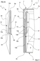
- the container 1 also comprises at least one spacer 30, also made of sheet material, optionally paper, interposed between the tab 13a of the second coupling portion 13 and the panel 41 of the lateral wall 4.
- the spacer 30 is at least partly facing the tab 13a of the second coupling portion 13 and is configured for opposing the contact between the end portion of the tab 13a and the panel, in particular preventing the contact between the grip edge 13b and the panel 41 (optionally the first panel 41).
- the spacer 30 is configured for maintaining a predetermined distance between said panel 41 of the lateral wall and the tab 13a of the second coupling portion 13, optionally between the first panel 41, and the end portion of the tab 13a (optionally the grip edge 13b) of the second coupling portion 13.
- the spacer 30 is configured for maintaining the tab 13a tilted with respect to the panel 41 (optionally al first panel 41), also in the second operative position of the tab 13a. In this manner, the spacer only allows a minimum displacement of the tab 13a, preventing undesired excessive deformations of the tab, such to compromise the operation thereof; in addition, the spacer 30 allows forcing the tab 13a to maintain the first operative position in which said tab 13a engages the first coupling portion; in this manner, the spacer is capable of ensuring the correct engagement of the first and second coupling portions such to render the container highly effective against opening by children.
- the spacer 30 comprises at least one tab 31 made of sheet material, optionally paper, directly carried by at least one between the panel of the lateral wall 4 and the tab 13a of the second coupling portion 13.
- the auxiliary tab 31 is at least partly facing the tab 13a of the second coupling portion 13 to essentially define a kind of counter-thickness suitable for maintaining at a distance, in any one operative condition of the second coupling portion, the grip edge 13b (optionally, more generally, an end portion of the tab 13a opposite the attachment edge 13c) of the tab 13a with the panel 41, optionally with the first panel 13a.
- the auxiliary tab 31 of the spacer 30 is integrally joined with the tab 13a at the grip edge 13b; the auxiliary tab 31 is overlapped to the tab 13a, in particular is folded above the tab 13a starting from the grip edge 13b: in such embodiment, the auxiliary tab 31 may be constrained to the tab 13a, for example by means of gluing in a manner such that said auxiliary tab 31 may be extended substantially parallel to the section of the tab 13a of the second coupling portion 13 directly facing said auxiliary tab 31.
- the auxiliary tab 31 defines a kind of counter-thickness carried directly by the tab 13a of the second coupling portion: the auxiliary tab 31, in the first operative position, is spaced from the first panel 41 while in the second operative position is configured for contacting the first panel 41 to prevent the grip edge 13b from contacting said first panel 41, obstructing the complete folding of the tab 13a.
- auxiliary tab 31 constrained to the grip edge 13 of the tab 13a, movable with respect to said tab (condition not illustrated).
- the auxiliary tab 31 may be folded with respect to the tab 13a of the second coupling portion 13 at the grip edge 13b to define a return element, for example of elastic type configured for contacting the panel (in particular the first panel 41) to push the tab 13a in the first operative position.
- the auxiliary tab 31 is configured for forcing the tab 13a to maintain the first operative position.
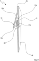
- the auxiliary tab 31 of the spacer 30 is integrally joined with the tab 13a of the second coupling portion 13 and defines, with said tab 13a, a single tab configured for normally maintaining a substantially "V"-shaped conformation adapted to force the movement of the tab 13a in the first operative position.
- auxiliary tab 31 may be integrally joined with the panel 41 and folded with respect to said panel towards the tab 13a.
- the auxiliary tab 31 defines a counter-thickness carried directly by the first panel 41 which is configured for contacting the tab 13a of the second coupling portion in the second operative position to maintain the end portion (optionally the grip edge 13b) of the tab 13a at a distance from the first panel 41, thus preventing an excessive folding of the tab 13a in the seat 43.
- the auxiliary tab 31 may be extended along a plane parallel to a lying plane of the first panel 41 ( figures 10 and 11 ).
- the auxiliary tab 31 may be integrally joined with the panel 41 and folded with respect to said panel to define a return element, e.g. of elastic type.
- the auxiliary tab 31 defines a single body with said first panel 41, configured for normally maintaining a substantially "V"-shaped conformation suitable for forcing the first operative position of the tab 13a.
- the defined return element of the auxiliary tab 31, at least in the second operative position of the second coupling portion 13, is configured for contacting the tab 13a of the second coupling portion 13 to push said tab 13a in the first operative position: the auxiliary tab 31 is thus configured for forcing the tab 13a to maintain the first operative position.
- the spacer 30 may comprise a first and a second auxiliary tab 31a, 31b overlapped to each other and both engaged with the first panel 41; the first and second auxiliary tabs 31a, 31b may be joined together by means of gluing to define a kind of double thickness: the first and second auxiliary tabs 31a, 31b may then lie on respective ideal planes that are substantially parallel to each other.
- auxiliary tab 31 of the spacer 30 may be carried by an intermediate panel interposed between the first and second panels ( figure 13 and 14 ).
- the spacer 30 is at least partly arranged in the seat 43 of the second panel 42.
- the auxiliary tab 31, at least in the second operative position of the tab 13a, is arranged at least in part in the seat 43 and configured for obstructing the insertion of said tab 13a in the seat 43 of the second panel 42.
- the tab 13a is configured for being moved with respect to the lateral wall 4 of the storage, at least in the closed condition (optionally also in the locking condition) of the container; such movement allows a safe closure of the container 1 and simultaneously allows a user to execute a quick and easy opening of the same.
- the spacer 30 is configured for preventing, in the closed and/or locking condition of the container, the tab 13a of the second coupling portion from being locked in the second operative position, thus preventing the locking of the container 1 in the closed condition, and it prevents undesired deformations in the tab 13a which may damage the structure thereof, e.g. reducing the elastic return properties of the same.
- the container 1 may also comprise an unlocking portion 60 configured for defining at least one through access 61 on the closure system (optionally on a lateral wall of the closure system), at the first and second coupling portions 12, 13; the unlocking portion 60 is configured for allowing a user, at least in the locking condition and from outside the container, to access at least one of said first and second coupling portions 12, 13 to allow the disengagement thereof.
- an unlocking portion 60 configured for defining at least one through access 61 on the closure system (optionally on a lateral wall of the closure system), at the first and second coupling portions 12, 13; the unlocking portion 60 is configured for allowing a user, at least in the locking condition and from outside the container, to access at least one of said first and second coupling portions 12, 13 to allow the disengagement thereof.
- the unlocking portion 60 is configured for allowing a user, at least in the locking condition and from outside the container, to intervene (e.g. manually and/or by means of an opening device insertable through the through access 61) on the tab 13a of the second coupling portions 13.
- the unlocking portion 60 may comprise, in a non-limiting manner, a through access 61 defined on at least one lateral wall of the closure system 7.
- the unlocking portion 60 may comprise a deformable portion (not shown in the enclosed figures) placed, in the locking condition, in front of the first and second coupling portions 12, 13: in such configuration, the unlocking portion 60 essentially comprises a thrust portion configured for being moved (manually by the user or by means of an opening device) between a thrust condition and a rest condition. In the rest condition, the thrust portion is spaced from at least one of said first and second coupling portions (optionally by both coupling portions), while in the thrust condition the thrust portion operates on the at least one of said first and second coupling portions 12, 13 to allow the disengagement thereof.
- the thrust portion may act functionally as a button.
- the push of a user's finger on the thrust portion according to a direction entering the container allows the thrust portion to come into contact with the second coupling portion 13, disengaging it from the undercut of the first coupling portion 12.
- the thrust portion may be reversibly movable between the thrust condition and the rest condition.
- the thrust portion may be elastically deformable between the thrust condition and the rest condition.
- the container may comprise only one unlocking portion 60 suitable for allowing the intervention by the user on the plurality of second coupling portion or it may comprise a dedicated unlocking portion 60 for each second coupling portion 13.
- Also forming the object of the present invention is a process of making a container 1 according to the description reported above and/or according to any one of the enclosed claims.
- the process comprises a step of arranging the storage 2; such step may provide for the die cutting of a flat sheet in paper material to define a blank which, due to subsequent steps of folding and gluing, defines said storage 2.
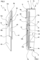
- the blank 50 used for making the storage 2 comprises:
- the process comprises the steps of:
- the blank of the present invention comprises the auxiliary sheet employed for making the spacer.
- the blank 50 of figure 1 when folded is configured for defining the wall illustrated in figures 2 and 3 .
- the blank 50 of figure 8 when folded, is configured for defining the lateral wall 4 illustrated in figures 9 and 10 .
- the blank 50 of figure 12 when folded, is configured for defining the lateral wall 4 illustrated in figures 13 and 14 .
- the blank 50 of figure 15 when folded, is configured for defining the lateral wall 4 illustrated in figures 16 and 17 .
- the blank 50 may comprise central sheet having rectangular shape from which a blank portion emerges for each side, as illustrated in figures 1 , 8 , 12 and 15 ; in particular, the container 1 of figure 5 was made by means of the blank 50 of figure 1 , in detail by means of four blanks according to figure 1 , each emerging from a flat central sheet having rectangular shape.
- the first lateral sheet 52 may comprise a first portion 52a suitable for defining the second panel 42 of the lateral wall of the storage 2 and at least one second portion 52b configured for defining the tab 13a of the second coupling portion 13.
- the first portion 52a of the first lateral wall 52 comprises a notch 56 suitable for defining the seat 44 of the second panel 42 and from which the second portion 52b is obtained.
- the second lateral sheet 53 comprises a single portion 53a configured for defining the first panel 41 of the lateral wall of the storage 2.
- the auxiliary sheet 54 comprises at least one first portion 54a integrally joined with at least one between: the first portion 52a of the first lateral sheet 52, the second portion 52b of the first lateral sheet 52, the second lateral sheet 53.
- the auxiliary sheet 54 comprises a first and a second portion 54a, 54b that are integrally joined; the process comprises a step of folding the blank 50 in a manner such that said first and second portions 54a, 54b of the auxiliary sheet 54 may define the first and second auxiliary tabs 31a, 31b of the spacer 30.
- the present invention involves advantages with respect to the solutions of the state of the art.
- the tab 13a of the second coupling portion 13 is movable with respect to the closure system; it is indicated that an excessive folding of the tab 13a and/or a prolonged use of the container can damage the second coupling portion 13, for example reducing the capacity thereof to maintain the first operative position.
- the spacer 30 allows, also following an extended use, to support the tab 13a in a manner such that the same may correctly define the first operative position in which it engages the first coupling portion 12.
- the spacer 30 prevents the tab 13a from being locked in an undesired manner against the lateral wall, for example in the seat 43.
Landscapes
- Engineering & Computer Science (AREA)
- Mechanical Engineering (AREA)
- Packaging Of Annular Or Rod-Shaped Articles, Wearing Apparel, Cassettes, Or The Like (AREA)
- Cartons (AREA)
- Table Devices Or Equipment (AREA)
Claims (15)
- Kindersicherer Behälter (1), umfassend:- einen Aufbewahrungsraum (2), welcher eine Kammer (3) definiert und eine laterale Wand (4) aufweist, welche eine Durchgangsöffnung definiert, die durch einen freien Rand (6) begrenzt ist, wobei die Durchgangsöffnung dazu eingerichtet ist, die Kammer (3) in Kommunikation mit der Außenumgebung zu setzen,- ein Verschlusssystem (7), welches in Bezug auf den Aufbewahrungsraum (2) beweglich ist, wenigstens zwischen:∘ einem geschlossenen Zustand, in welchem das Verschlusssystem (7) die Kommunikation zwischen der Kammer (3) und der Außenumgebung verhindert,∘ einem offenen Zustand, in welchem das Verschlusssystem (7) die Kommunikation zwischen der Kammer (3) und der Außenumgebung ermöglicht,- wenigstens einen ersten Kopplungsabschnitt (12), welcher durch das Verschlusssystem (7) getragen ist,- wenigstens einen zweiten Kopplungsabschnitt (13), welcher durch den Aufbewahrungsraum (2) getragen ist und dazu eingerichtet ist, mit dem ersten Kopplungsabschnitt (12) zusammenzuwirken,wobei der erste und der zweite Kopplungsabschnitt (12, 13) dazu eingerichtet sind, in dem geschlossenen Zustand des Behälters miteinander in Eingriff gebracht zu sein, um einen Verriegelungszustand zu definieren, in welchem der erste und der zweite Kopplungsabschnitt (12, 13) verhindern, dass das Verschlusssystem (7) von dem geschlossenen Zustand in den offenen Zustand übergeht,wobei der zweite Kopplungsabschnitt (13) wenigstens eine Lasche (13a) außerhalb der Kammer (3) umfasst und wenigstens eine Hinterschneidung definiert, welche dazu eingerichtet ist, mit dem ersten Kopplungsabschnitt (12) des Verschlusssystems (7) in Eingriff zu treten, um den Verriegelungszustand zu definieren,wobei der Behälter (1) wenigstens einen Abstandshalter (30) umfasst, welcher wenigstens teilweise zwischen der Lasche (13a) des zweiten Kopplungsabschnitts (13) und der lateralen Wand (4) des Aufbewahrungsraums (2) eingefügt ist,gekennzeichnet durch die Tatsache, dass die Lasche (13a) des zweiten Kopplungsabschnitts (13) in dem geschlossenen Zustand beweglich ist, wenigstens zwischen:- einer ersten wirksamen Position, in welcher die Lasche (13a) dazu eingerichtet ist, mit dem ersten Kopplungsabschnitt (12) in Eingriff zu treten, um den Verriegelungszustand zu definieren,- einer zweiten wirksamen Position, in welcher die Lasche (13a) dazu eingerichtet ist, den ersten Kopplungsabschnitt (12) freizugeben, um den Übergang des Verschlusssystems (7) von dem geschlossenen Zustand in den offenen Zustand zu ermöglichen.
- Behälter nach dem vorhergehenden Anspruch, wobei die laterale Wand (4) des Aufbewahrungsraums (2) wenigstens ein Paneel (41) umfasst,wobei der Abstandshalter (30) wenigstens teilweise zwischen der Lasche (13a) des zweiten Kopplungsabschnitts (13) und dem Paneel (41) der lateralen Wand (4) eingefügt ist,wobei wenigstens ein Teil der Lasche (13a) des zweiten Kopplungsabschnitts (13) in Bezug auf das Paneel (41) außerhalb der Kammer (3) austritt, um die Hinterschneidung zu definieren,wobei wenigstens ein Teil der Lasche (13a) des zweiten Kopplungsabschnitts in der ersten wirksamen Position von dem Paneel (41) der lateralen Wand (4) beabstandet ist, wobei der Abstandshalter (30) in dem geschlossenen Zustand dazu eingerichtet ist, wenigstens den Teil der Lasche (13a) des zweiten Kopplungsabschnitts (13) von dem Paneel (41) der lateralen Wand (4) zu beabstanden,optional wobei die Lasche (13a) des zweiten Kopplungsabschnitts in der zweiten wirksamen Position in einem Abstand von dem Paneel (41) angeordnet ist, welcher kleiner ist als ein Abstand, der zwischen dem Paneel (41) und der Lasche (13a) vorhanden ist, wenn sich die Lasche (13a) in der ersten wirksamen Position befindet.
- Behälter nach dem vorhergehenden Anspruch, wobei wenigstens ein Endabschnitt der Lasche (13a) des zweiten Kopplungsabschnitts (13) in der ersten wirksamen Position von dem Paneel (41) der lateralen Wand (4) beabstandet ist, um die Hinterschneidung zu definieren.
- Behälter nach einem der vorhergehenden Ansprüche, wobei der Abstandshalter (30) eine Hilfslasche (31) umfasst, welche integral mit der Lasche (13a) des zweiten Kopplungsabschnitts (13) verbunden ist, wobei die Hilfslasche (31) in Bezug auf die Lasche (13a) des zweiten Kopplungsabschnitts (13), optional an dem Endabschnitt, gefaltet ist,
optional wobei die Hilfslasche (31) des Abstandshalters (30) ein Rückstellelement definiert, welches in der zweiten wirksamen Position dazu eingerichtet ist, eine Kraft auf die Lasche (13a) des zweiten Kopplungsabschnitts (13) auszuüben, um die erste wirksame Position beizubehalten. - Behälter nach einem der vorhergehenden Ansprüche, wobei der Abstandshalter (30) in dem geschlossenen Zustand von dem freien Rand (6) des Aufbewahrungsraums (2) beabstandet ist.
- Behälter nach einem der vorhergehenden Ansprüche, wobei die Lasche (13a) des zweiten Kopplungsabschnitts (13) wenigstens teilweise durch einen Greifrand (13b) begrenzt ist, welcher in der ersten wirksamen Position dazu eingerichtet ist, wenigstens einen Teil der Hinterschneidung zu definieren, welche dazu geeignet ist, mit dem ersten Kopplungsabschnitt (12) in Eingriff zu treten, wobei der Greifrand (13b) in der ersten wirksamen Position von dem Paneel (41) beabstandet ist.
- Behälter nach einem der Ansprüche 4 bis 6, wobei die Hilfslasche (31) des Abstandshalters in Zwangsverbindung mit der Lasche (13a) des zweiten Kopplungsabschnitts (13) steht, optional daran geklebt ist,wobei die Hilfslasche (31) des Abstandshalters (30) dazu eingerichtet ist, zusammen mit der Lasche (13a) des zweiten Kopplungsabschnitts (13) zwischen der ersten und der zweiten wirksamen Position und umgekehrt bewegt zu werden,optional wobei sich die Hilfslasche (31) des Abstandshalters in dem offenen Zustand parallel zu der Lasche (13a) des zweiten Kopplungsabschnitts (13) erstreckt.
- Behälter nach einem der Ansprüche 4 bis 7, wobei die Hilfslasche (31) des Abstandshalters (30) direkt durch das Paneel (41) der lateralen Wand (4) getragen ist und in Bezug auf das Paneel (41) in Richtung der Lasche (13a) des zweiten Kopplungsabschnitts (13) gefaltet ist.
- Behälter nach einem der Ansprüche 4 bis 6, wobei die Hilfslasche (31) des Abstandshalters (30) mit der Lasche (13a) des zweiten Kopplungsabschnitts (13) eine einzelne Lasche definiert, welche dazu eingerichtet ist, normalerweise eine im Wesentlichen "V"-förmige Konfiguration beizubehalten, und optional dazu eingerichtet ist, eine Kraft auf die Lasche (13a) des zweiten Kopplungsabschnitts (13) auszuüben, um die erste wirksame Position beizubehalten,
optional wobei die einzelne Lasche in dem geschlossenen Zustand des Behälters eine im Wesentlichen "V"-förmige Form aufweist, und noch mehr optional dazu eingerichtet ist, eine Kraft auf die Lasche (13a) des zweiten Kopplungsabschnitts (13) auszuüben, um die erste wirksame Position beizubehalten. - Behälter nach dem vorhergehenden Anspruch, wobei- die Hilfslasche (31) des Abstandshalters (30) mit dem Paneel (41) überlappt ist, wobei die Hilfslasche (31) des Abstandshalters (30) mit dem Paneel (41), optional durch einen Kleber, in Zwangsverbindung steht, oder- die Hilfslasche (31) des Abstandshalters (30) integral mit dem Paneel (41) verbunden ist, wobei die Hilfslasche (31) in Bezug auf das Paneel (41) gefaltet ist, um ein Rückstellelement zu definieren, welches in der zweiten wirksamen Position des zweiten Kopplungsabschnitts (13) dazu eingerichtet ist, die Lasche (13a) des zweiten Kopplungsabschnitts (13) zu kontaktieren, um die Lasche (13a) in die erste wirksame Position zu drücken.
- Behälter nach einem der vorhergehenden Ansprüche, wobei die laterale Wand (4) des Aufbewahrungsraums (2) ein erstes und ein zweites Paneel (41, 42) umfasst, welche einander zugewandt sind und miteinander in Eingriff stehen, wobei das erste Paneel (41) wenigstens einen Teil einer inneren Fläche definiert, welche einen Teil der Kammer (3) des Aufbewahrungsraums (2) begrenzt, wobei das zweite Paneel (42) , optional entgegengesetzt zu einer inneren Fläche, welche die Kammer (3) des Aufbewahrungsraums (2) begrenzt, wenigstens einen Teil einer äußeren Fläche des Aufbewahrungsraums (2) definiert,
wobei die Lasche (13a) des zweiten Kopplungsabschnitts (13) einen Befestigungsrand (13c) umfasst, welcher integral mit dem zweiten Paneel (42) verbunden ist, optional wobei der zweite Kopplungsabschnitt (13) über ein Einkerben des zweiten Paneels (42) hergestellt ist. - Behälter nach dem vorhergehenden Anspruch, wobei das zweite Paneel (42) eine Aufnahme (43) umfasst, welche durch einen Umfangsrand (44) begrenzt ist, wobei der Abstandshalter (30) wenigstens teilweise in der Aufnahme (43) angeordnet ist, wobei die Lasche (13a) des zweiten Kopplungsabschnitts (13) der Aufnahme (43) zugewandt ist,
wobei die Hilfslasche (31) des Abstandshalters (30) wenigstens in der zweiten wirksamen Position wenigstens teilweise in der Aufnahme (43) angeordnet ist, wobei die Hilfslasche (31) dazu eingerichtet ist, das Einsetzen der Lasche (13a) des zweiten Kopplungsabschnitts (13) in die Aufnahme (43) des zweiten Paneels (42) zu behindern. - Behälter nach Anspruch 11 oder 12, wobei die Lasche (13a) des zweiten Kopplungsabschnitts (13) in dem geschlossenen Zustand nahe an das erste Paneel (41) und davon weg beweglich ist, wobei der Abstandshalter (30) dazu eingerichtet ist, die Lasche (13a) des zweiten Kopplungsabschnitts von dem ersten Paneel (41) beabstandet zu halten.
- Behälter nach einem der vorhergehenden Ansprüche, wobei die Lasche (13a) des zweiten Kopplungsabschnitts (13) in der ersten wirksamen Position in Bezug auf das Paneel (41) der lateralen Wand (4) in einem Winkel geneigt ist, welcher größer ist als ein Winkel, der zwischen demselben Paneel (41) und derselben Lasche (13a) aufgespannt ist, wenn sich die Lasche (13a) in der zweiten wirksamen Position befindet,
wobei die Hilfslasche (31) des Abstandshalters (30) dazu eingerichtet ist, die Lasche (13a) des zweiten Kopplungsabschnitts (13) in Bezug auf das Paneel (41) der lateralen Wand geneigt zu halten. - Verfahren zur Herstellung eines Behälters (1) im Einklang mit einem der vorhergehenden Ansprüche, wobei das Verfahren die folgenden Schritte umfasst:- Anordnen eines ersten flachen Zuschnitts (50), welcher optional aus einem Papierbahnmaterial mittels eines Stanzens einer flachen halbfertigen Bahn hergestellt ist,- Falten des ersten Zuschnitts (50), um den Aufbewahrungsraum (2) zu erhalten,- Anordnen eines flachen zweiten Zuschnitts (70), welcher optional aus einem Papierbahnmaterial mittels eines Stanzens einer flachen halbfertigen Bahn hergestellt ist,- Falten des zweiten Zuschnitts (70), um das Verschlusssystem (7) zu erhalten.
Applications Claiming Priority (1)
| Application Number | Priority Date | Filing Date | Title |
|---|---|---|---|
| IT102021000025892A IT202100025892A1 (it) | 2021-10-08 | 2021-10-08 | Contenitore a prova di bambino |
Publications (3)
| Publication Number | Publication Date |
|---|---|
| EP4163219A1 EP4163219A1 (de) | 2023-04-12 |
| EP4163219B1 true EP4163219B1 (de) | 2024-08-28 |
| EP4163219C0 EP4163219C0 (de) | 2024-08-28 |
Family
ID=79018643
Family Applications (1)
| Application Number | Title | Priority Date | Filing Date |
|---|---|---|---|
| EP22198509.6A Active EP4163219B1 (de) | 2021-10-08 | 2022-09-28 | Kindersicherer behälter und verfahren zu seiner herstellung |
Country Status (3)
| Country | Link |
|---|---|
| US (1) | US11945629B2 (de) |
| EP (1) | EP4163219B1 (de) |
| IT (1) | IT202100025892A1 (de) |
Families Citing this family (11)
| Publication number | Priority date | Publication date | Assignee | Title |
|---|---|---|---|---|
| US20220332480A1 (en) * | 2019-09-02 | 2022-10-20 | I.G.B. S.R.L. | Coupling system, process of making the same, child-proof container and child-proof package |
| HUE064013T2 (hu) | 2020-12-11 | 2024-02-28 | Procter & Gamble | Mosószertermék tartály zárral |
| HUE068913T2 (hu) * | 2021-02-09 | 2025-02-28 | Procter & Gamble | Fedél tapintható folytonossági hiányokkal |
| HUE062361T2 (hu) | 2021-03-15 | 2023-10-28 | Procter & Gamble | Mosószertároló zárral és keresztirányú fallal |
| EP4071073B1 (de) * | 2021-04-06 | 2023-09-27 | Fameccanica.Data S.p.A. | Kindersicherer papier- oder kartonbehälter |
| DE202022104856U1 (de) | 2022-08-29 | 2023-12-01 | Gpi Frankfurt & Augsburg Gmbh | Faltschachtel mit Klick-Laschen |
| IT202300005976A1 (it) | 2023-03-28 | 2024-09-28 | Igb Srl | Contenitore a prova di bambino e procedimento per la realizzazione dello stesso |
| EP4727858A1 (de) * | 2023-06-16 | 2026-04-22 | DS Smith Packaging Limited | Behälter |
| EP4512731A1 (de) * | 2023-08-23 | 2025-02-26 | Fameccanica.Data S.p.A. | Kindersicherer papier- oder kartonbehälter, zuschnitt dafür und verbraucherprodukt damit |
| EP4570685A1 (de) * | 2023-12-11 | 2025-06-18 | The Procter & Gamble Company | Verbraucherprodukte und verfahren zum betrieb davon |
| PL448138A1 (pl) * | 2024-03-29 | 2025-10-06 | Tfp - Grafika Spółka Z Ograniczoną Odpowiedzialnością | Wykrój opakowania zamykanego |
Family Cites Families (69)
| Publication number | Priority date | Publication date | Assignee | Title |
|---|---|---|---|---|
| US3126092A (en) * | 1964-03-24 | Cigarette package with ashtray | ||
| US1130271A (en) * | 1914-03-26 | 1915-03-02 | James B Stoddard | Self-locking box. |
| US1253489A (en) | 1917-03-08 | 1918-01-15 | Economy Folding Box Co | Folding container. |
| FR783262A (fr) * | 1934-12-15 | 1935-07-10 | Boîte en carton à fermeture inviolable | |
| US2395364A (en) * | 1944-03-03 | 1946-02-19 | Gaylord Container Corp | Container |
| US2456841A (en) * | 1945-06-22 | 1948-12-21 | Gaylord Container Corp | Container |
| US2559320A (en) * | 1946-03-14 | 1951-07-03 | Gaylord Container Corp | Container having cover locking means |
| US2695128A (en) * | 1949-09-23 | 1954-11-23 | Gaylord Container Corp | Shipping container |
| US2777629A (en) * | 1955-09-30 | 1957-01-15 | Birmingham Paper Company | Folding carton with self-locking cover |
| US2809775A (en) * | 1956-10-01 | 1957-10-15 | Lawrence Paper Co | Container |
| US2970742A (en) * | 1959-01-28 | 1961-02-07 | Charles J Fleisig | Paper boxes for mailing |
| US3187980A (en) * | 1963-07-29 | 1965-06-08 | Int Paper Co | Container |
| US3642193A (en) * | 1970-01-05 | 1972-02-15 | Container Corp | Locking construction for telescoping container elements |
| US3692231A (en) * | 1970-12-18 | 1972-09-19 | Weyerhaeuser Co | Means for locking a lid to a container |
| US4053100A (en) * | 1976-09-01 | 1977-10-11 | International Paper Company | Shipping carton |
| US4113104A (en) * | 1977-06-09 | 1978-09-12 | American Can Company | Tamperproof reclosable carton |
| US4196843A (en) * | 1978-12-13 | 1980-04-08 | Champion International Corporation | Two-piece container with self-locking cover |
| US4326634A (en) * | 1980-09-26 | 1982-04-27 | American Can Company | Side loading, top opening, reclosable carton |
| US4483095A (en) * | 1983-09-06 | 1984-11-20 | Champion International Corporation | Telescoping container |
| US4717070A (en) * | 1987-03-30 | 1988-01-05 | Clifford Taub | Storage box with locking cover |
| ITBO20020401A1 (it) * | 2002-06-24 | 2003-12-24 | Gd Spa | Stecca rigida di pacchetti di sigarette |
| FR2655951B2 (fr) * | 1989-05-12 | 1992-03-13 | Bull Sa | Boite d'emballage a fermeture autoverrouillable et procede d'emballage. |
| US4964561A (en) * | 1989-06-12 | 1990-10-23 | Inland Container Corporation | Self-locking carton |
| US5351819A (en) * | 1993-12-10 | 1994-10-04 | Carter-Wallace, Inc. | Sleep therapy package |
| US5398868A (en) * | 1994-05-31 | 1995-03-21 | Densen; Mark S. | Foldable knock-down storage box with detachable hingeable cover |
| US5515996A (en) * | 1994-06-06 | 1996-05-14 | Packaging Corporation Of America | Flip-top recloseable container with positive closure arrangement |
| US5505374A (en) * | 1995-07-13 | 1996-04-09 | Packaging Corporation Of America | Flip-top reclosable carton and method of making the same |
| US5725144A (en) * | 1996-06-26 | 1998-03-10 | Tenneco Packaging | Collapsible paperboard carton |
| US6484931B1 (en) * | 1999-03-04 | 2002-11-26 | The Procter & Gamble Company | Sift-resistant cartons having slotted closure structures |
| US6168073B1 (en) * | 1999-06-21 | 2001-01-02 | Allpak Container, Inc. | Container having a sliding inner member |
| US6604676B2 (en) * | 1999-12-29 | 2003-08-12 | Unilever Home & Personal Care Usa, Division Of Conopco, Inc. | Lip-lock carton for powders |
| US6296175B1 (en) * | 2000-03-17 | 2001-10-02 | Mpc Packaging Corporation | Tamper resistant container |
| US6491211B1 (en) | 2001-08-03 | 2002-12-10 | Scott & Daniells, Inc. | Child resistant carton and method for using the same |
| EP1323635A1 (de) | 2001-12-13 | 2003-07-02 | Rondo AG | Verpackung, insbesondere Faltschachtel aus Karton |
| US20030222130A1 (en) * | 2002-04-29 | 2003-12-04 | The Procter & Gamble Company | Paperboard carton having an audible locking sound |
| US6708874B1 (en) * | 2002-05-28 | 2004-03-23 | Footstar Corporation | Carton with finger holes |
| US7658318B2 (en) * | 2002-12-13 | 2010-02-09 | Graphic Packaging International, Inc. | Packages, blanks for making packages and associated methods |
| CN1953916A (zh) | 2004-01-07 | 2007-04-25 | 米德韦斯瓦科公司 | 泡罩和包装件系统 |
| EP1778550A1 (de) * | 2004-08-02 | 2007-05-02 | Life Order Products Pty Ltd | Stapelbarer lagerungskasten für hängemappen mit getrenntem boden und deckel |
| US7249674B2 (en) * | 2005-08-17 | 2007-07-31 | Der Liang Mu | Multi-functional shoe storage box |
| US7726552B2 (en) * | 2006-08-30 | 2010-06-01 | Mike Chadima | System for secure collection and disposal of large volumes of documents |
| US9027826B2 (en) * | 2007-05-02 | 2015-05-12 | Watson Laboratories, Inc. | Frangible shipping carton and associated methods |
| JP5237603B2 (ja) | 2007-09-21 | 2013-07-17 | 株式会社ロッテ | 包装容器 |
| WO2012112538A1 (en) | 2011-02-14 | 2012-08-23 | Meadwestvaco Corporation | Container with locking or retention feature |
| US8499936B2 (en) | 2011-03-15 | 2013-08-06 | Nosco, Inc. | Product packaging system with button lock release |
| US8646680B2 (en) * | 2012-01-30 | 2014-02-11 | OIA Global Logistics SCM, INC. | Sheet and folding method for self-latching clamshell folded box |
| JP5891053B2 (ja) | 2012-02-01 | 2016-03-22 | 凸版印刷株式会社 | 開閉蓋付き包装容器 |
| US20140262839A1 (en) | 2013-03-15 | 2014-09-18 | Meadwestvaco Corporation | Packages and packaging kits with deactivatable and activatable locking features |
| DE102013105394A1 (de) | 2013-05-27 | 2014-11-27 | Van Genechten Packaging N.V. | Verpackung |
| US9981788B2 (en) * | 2014-07-01 | 2018-05-29 | Ingersoll Paper Box Co., Limited | Child-resistant package |
| CN204642380U (zh) | 2015-02-09 | 2015-09-16 | 浙江理工大学 | 一种具备儿童防护功能的双向滑动开启药品包装盒 |
| US9783335B2 (en) * | 2015-02-27 | 2017-10-10 | Munson Whitman Everett | Child-resistant packaging systems and methods |
| WO2016138305A1 (en) | 2015-02-27 | 2016-09-01 | Everett Munson Whitman | Child-resistant packaging systems and methods |
| US10479581B2 (en) * | 2016-04-14 | 2019-11-19 | All Packaging Company | Locking packaging container |
| US10934072B2 (en) * | 2017-08-31 | 2021-03-02 | Lantz Packaging, LLC | Child-resistant senior-friendly packaging |
| US10934064B2 (en) * | 2017-11-08 | 2021-03-02 | The Procter & Gamble Company | Consumer product that includes a container and unit dose articles |
| US20210047072A1 (en) * | 2019-08-14 | 2021-02-18 | The Procter & Gamble Company | Consumer product |
| IT201900015399A1 (it) * | 2019-09-02 | 2021-03-02 | Igb Srl | Confezione a prova di bambino e procedimento per la realizzazione della stessa, metodo di chiusura ed apertura di detta confezione |
| IT201900015354A1 (it) | 2019-09-02 | 2021-03-02 | Igb Srl | Confezione a prova di bambino e procedimento per la realizzazione della stessa, metodo di chiusura ed apertura di detta confezione |
| US11263809B2 (en) | 2019-09-06 | 2022-03-01 | Shandong University | TBM-mounted virtual reconstruction system and method for surrounding rock structure of tunnel |
| ES2932508T3 (es) * | 2020-05-08 | 2023-01-20 | Procter & Gamble | Recipiente de producto detergente con cierre |
| ES3042438T3 (en) * | 2020-07-09 | 2025-11-20 | Procter & Gamble | Lid for a cardboard container wherein the lid comprises a cardboard support element |
| CN213414846U (zh) * | 2020-08-17 | 2021-06-11 | 深圳市季霈环保科技有限公司 | 一种带有锁扣结构的防盗盒 |
| EP3967617B1 (de) * | 2020-09-15 | 2023-07-05 | The Procter & Gamble Company | Kartondeckel, kartonzuschnitt, verfahren zur herstellung eines konsumguts |
| HUE064013T2 (hu) * | 2020-12-11 | 2024-02-28 | Procter & Gamble | Mosószertermék tartály zárral |
| EP4039605B1 (de) * | 2021-02-09 | 2024-01-31 | The Procter & Gamble Company | Abdeckung mit ersten, zweiten und dritten betätigungsbereichen |
| HUE062361T2 (hu) * | 2021-03-15 | 2023-10-28 | Procter & Gamble | Mosószertároló zárral és keresztirányú fallal |
| EP4071073B1 (de) * | 2021-04-06 | 2023-09-27 | Fameccanica.Data S.p.A. | Kindersicherer papier- oder kartonbehälter |
| US20230142224A1 (en) * | 2021-11-05 | 2023-05-11 | Jeremiah J. Buck | Child-resistant package |
-
2021
- 2021-10-08 IT IT102021000025892A patent/IT202100025892A1/it unknown
-
2022
- 2022-09-28 EP EP22198509.6A patent/EP4163219B1/de active Active
- 2022-10-07 US US17/962,412 patent/US11945629B2/en active Active
Also Published As
| Publication number | Publication date |
|---|---|
| US11945629B2 (en) | 2024-04-02 |
| IT202100025892A1 (it) | 2023-04-08 |
| EP4163219C0 (de) | 2024-08-28 |
| US20230113321A1 (en) | 2023-04-13 |
| EP4163219A1 (de) | 2023-04-12 |
Similar Documents
| Publication | Publication Date | Title |
|---|---|---|
| EP4163219B1 (de) | Kindersicherer behälter und verfahren zu seiner herstellung | |
| EP3997002B1 (de) | Kindersichere verpackung, verfahren zu ihrer herstellung und verfahren zum öffnen derselben | |
| EP4025510B1 (de) | Kindersichere verpackung und verfahren zur herstellung derselben | |
| US8939281B2 (en) | Packaging | |
| US10273069B2 (en) | Blister packaging | |
| US12202658B2 (en) | Wall and process of making the same, child-proof package | |
| US10710785B2 (en) | Lockable packaging and a release mechanism therefor | |
| US9376246B2 (en) | Blister packaging | |
| US20220250788A1 (en) | Child-proof package and process of making the same, method for closing and opening said package | |
| US12448188B2 (en) | Child-proof container | |
| CA2375893A1 (en) | Unit dose packaging system with exterior pocket feature | |
| AU2016275331A1 (en) | Child-proof container and process for making the same | |
| WO2013151806A1 (en) | Lockable packaging | |
| JP7648596B2 (ja) | 摺動リッドおよび係止機構を有する容器 | |
| IT202300005976A1 (it) | Contenitore a prova di bambino e procedimento per la realizzazione dello stesso | |
| WO2012121924A1 (en) | Loose fill packaging system | |
| US20220332480A1 (en) | Coupling system, process of making the same, child-proof container and child-proof package | |
| IT201900015357A1 (it) | Contenitore a prova di bambino e procedimento per la realizzazione dello stesso, metodo di chiusura ed apertura del contenitore | |
| US10106305B2 (en) | Package and associated container, process for making said package and said container | |
| IT202000006961A1 (it) | Contenitore e procedimento per la realizzazione dello stesso | |
| WO2010082876A1 (en) | Container with dispensing function |
Legal Events
| Date | Code | Title | Description |
|---|---|---|---|
| PUAI | Public reference made under article 153(3) epc to a published international application that has entered the european phase |
Free format text: ORIGINAL CODE: 0009012 |
|
| STAA | Information on the status of an ep patent application or granted ep patent |
Free format text: STATUS: THE APPLICATION HAS BEEN PUBLISHED |
|
| AK | Designated contracting states |
Kind code of ref document: A1 Designated state(s): AL AT BE BG CH CY CZ DE DK EE ES FI FR GB GR HR HU IE IS IT LI LT LU LV MC MK MT NL NO PL PT RO RS SE SI SK SM TR |
|
| P01 | Opt-out of the competence of the unified patent court (upc) registered |
Effective date: 20230510 |
|
| STAA | Information on the status of an ep patent application or granted ep patent |
Free format text: STATUS: REQUEST FOR EXAMINATION WAS MADE |
|
| 17P | Request for examination filed |
Effective date: 20231011 |
|
| RBV | Designated contracting states (corrected) |
Designated state(s): AL AT BE BG CH CY CZ DE DK EE ES FI FR GB GR HR HU IE IS IT LI LT LU LV MC MK MT NL NO PL PT RO RS SE SI SK SM TR |
|
| GRAP | Despatch of communication of intention to grant a patent |
Free format text: ORIGINAL CODE: EPIDOSNIGR1 |
|
| STAA | Information on the status of an ep patent application or granted ep patent |
Free format text: STATUS: GRANT OF PATENT IS INTENDED |
|
| INTG | Intention to grant announced |
Effective date: 20240418 |
|
| GRAS | Grant fee paid |
Free format text: ORIGINAL CODE: EPIDOSNIGR3 |
|
| GRAA | (expected) grant |
Free format text: ORIGINAL CODE: 0009210 |
|
| STAA | Information on the status of an ep patent application or granted ep patent |
Free format text: STATUS: THE PATENT HAS BEEN GRANTED |
|
| AK | Designated contracting states |
Kind code of ref document: B1 Designated state(s): AL AT BE BG CH CY CZ DE DK EE ES FI FR GB GR HR HU IE IS IT LI LT LU LV MC MK MT NL NO PL PT RO RS SE SI SK SM TR |
|
| REG | Reference to a national code |
Ref country code: CH Ref legal event code: EP |
|
| REG | Reference to a national code |
Ref country code: DE Ref legal event code: R096 Ref document number: 602022005661 Country of ref document: DE |
|
| REG | Reference to a national code |
Ref country code: IE Ref legal event code: FG4D |
|
| U01 | Request for unitary effect filed |
Effective date: 20240926 |
|
| U07 | Unitary effect registered |
Designated state(s): AT BE BG DE DK EE FI FR IT LT LU LV MT NL PT RO SE SI Effective date: 20241021 |
|
| P04 | Withdrawal of opt-out of the competence of the unified patent court (upc) registered |
Free format text: CASE NUMBER: APP_56630/2024 Effective date: 20241016 |
|
| U20 | Renewal fee for the european patent with unitary effect paid |
Year of fee payment: 3 Effective date: 20241025 |
|
| PG25 | Lapsed in a contracting state [announced via postgrant information from national office to epo] |
Ref country code: NO Free format text: LAPSE BECAUSE OF FAILURE TO SUBMIT A TRANSLATION OF THE DESCRIPTION OR TO PAY THE FEE WITHIN THE PRESCRIBED TIME-LIMIT Effective date: 20241128 |
|
| PG25 | Lapsed in a contracting state [announced via postgrant information from national office to epo] |
Ref country code: PL Free format text: LAPSE BECAUSE OF FAILURE TO SUBMIT A TRANSLATION OF THE DESCRIPTION OR TO PAY THE FEE WITHIN THE PRESCRIBED TIME-LIMIT Effective date: 20240828 Ref country code: GR Free format text: LAPSE BECAUSE OF FAILURE TO SUBMIT A TRANSLATION OF THE DESCRIPTION OR TO PAY THE FEE WITHIN THE PRESCRIBED TIME-LIMIT Effective date: 20241129 |
|
| PG25 | Lapsed in a contracting state [announced via postgrant information from national office to epo] |
Ref country code: IS Free format text: LAPSE BECAUSE OF FAILURE TO SUBMIT A TRANSLATION OF THE DESCRIPTION OR TO PAY THE FEE WITHIN THE PRESCRIBED TIME-LIMIT Effective date: 20241228 |
|
| PG25 | Lapsed in a contracting state [announced via postgrant information from national office to epo] |
Ref country code: HR Free format text: LAPSE BECAUSE OF FAILURE TO SUBMIT A TRANSLATION OF THE DESCRIPTION OR TO PAY THE FEE WITHIN THE PRESCRIBED TIME-LIMIT Effective date: 20240828 |
|
| PG25 | Lapsed in a contracting state [announced via postgrant information from national office to epo] |
Ref country code: RS Free format text: LAPSE BECAUSE OF FAILURE TO SUBMIT A TRANSLATION OF THE DESCRIPTION OR TO PAY THE FEE WITHIN THE PRESCRIBED TIME-LIMIT Effective date: 20241128 Ref country code: ES Free format text: LAPSE BECAUSE OF FAILURE TO SUBMIT A TRANSLATION OF THE DESCRIPTION OR TO PAY THE FEE WITHIN THE PRESCRIBED TIME-LIMIT Effective date: 20240828 |
|
| PG25 | Lapsed in a contracting state [announced via postgrant information from national office to epo] |
Ref country code: RS Free format text: LAPSE BECAUSE OF FAILURE TO SUBMIT A TRANSLATION OF THE DESCRIPTION OR TO PAY THE FEE WITHIN THE PRESCRIBED TIME-LIMIT Effective date: 20241128 Ref country code: PL Free format text: LAPSE BECAUSE OF FAILURE TO SUBMIT A TRANSLATION OF THE DESCRIPTION OR TO PAY THE FEE WITHIN THE PRESCRIBED TIME-LIMIT Effective date: 20240828 Ref country code: NO Free format text: LAPSE BECAUSE OF FAILURE TO SUBMIT A TRANSLATION OF THE DESCRIPTION OR TO PAY THE FEE WITHIN THE PRESCRIBED TIME-LIMIT Effective date: 20241128 Ref country code: IS Free format text: LAPSE BECAUSE OF FAILURE TO SUBMIT A TRANSLATION OF THE DESCRIPTION OR TO PAY THE FEE WITHIN THE PRESCRIBED TIME-LIMIT Effective date: 20241228 Ref country code: HR Free format text: LAPSE BECAUSE OF FAILURE TO SUBMIT A TRANSLATION OF THE DESCRIPTION OR TO PAY THE FEE WITHIN THE PRESCRIBED TIME-LIMIT Effective date: 20240828 Ref country code: GR Free format text: LAPSE BECAUSE OF FAILURE TO SUBMIT A TRANSLATION OF THE DESCRIPTION OR TO PAY THE FEE WITHIN THE PRESCRIBED TIME-LIMIT Effective date: 20241129 Ref country code: ES Free format text: LAPSE BECAUSE OF FAILURE TO SUBMIT A TRANSLATION OF THE DESCRIPTION OR TO PAY THE FEE WITHIN THE PRESCRIBED TIME-LIMIT Effective date: 20240828 |
|
| PG25 | Lapsed in a contracting state [announced via postgrant information from national office to epo] |
Ref country code: SM Free format text: LAPSE BECAUSE OF FAILURE TO SUBMIT A TRANSLATION OF THE DESCRIPTION OR TO PAY THE FEE WITHIN THE PRESCRIBED TIME-LIMIT Effective date: 20240828 |
|
| PG25 | Lapsed in a contracting state [announced via postgrant information from national office to epo] |
Ref country code: CZ Free format text: LAPSE BECAUSE OF FAILURE TO SUBMIT A TRANSLATION OF THE DESCRIPTION OR TO PAY THE FEE WITHIN THE PRESCRIBED TIME-LIMIT Effective date: 20240828 |
|
| PG25 | Lapsed in a contracting state [announced via postgrant information from national office to epo] |
Ref country code: SK Free format text: LAPSE BECAUSE OF FAILURE TO SUBMIT A TRANSLATION OF THE DESCRIPTION OR TO PAY THE FEE WITHIN THE PRESCRIBED TIME-LIMIT Effective date: 20240828 |
|
| PLBE | No opposition filed within time limit |
Free format text: ORIGINAL CODE: 0009261 |
|
| STAA | Information on the status of an ep patent application or granted ep patent |
Free format text: STATUS: NO OPPOSITION FILED WITHIN TIME LIMIT |
|
| PG25 | Lapsed in a contracting state [announced via postgrant information from national office to epo] |
Ref country code: MC Free format text: LAPSE BECAUSE OF FAILURE TO SUBMIT A TRANSLATION OF THE DESCRIPTION OR TO PAY THE FEE WITHIN THE PRESCRIBED TIME-LIMIT Effective date: 20240828 |
|
| PG25 | Lapsed in a contracting state [announced via postgrant information from national office to epo] |
Ref country code: IE Free format text: LAPSE BECAUSE OF NON-PAYMENT OF DUE FEES Effective date: 20240928 |
|
| 26N | No opposition filed |
Effective date: 20250530 |
|
| U20 | Renewal fee for the european patent with unitary effect paid |
Year of fee payment: 4 Effective date: 20250925 |
|
| PG25 | Lapsed in a contracting state [announced via postgrant information from national office to epo] |
Ref country code: CY Free format text: LAPSE BECAUSE OF FAILURE TO SUBMIT A TRANSLATION OF THE DESCRIPTION OR TO PAY THE FEE WITHIN THE PRESCRIBED TIME-LIMIT; INVALID AB INITIO Effective date: 20220928 |
|
| PG25 | Lapsed in a contracting state [announced via postgrant information from national office to epo] |
Ref country code: HU Free format text: LAPSE BECAUSE OF FAILURE TO SUBMIT A TRANSLATION OF THE DESCRIPTION OR TO PAY THE FEE WITHIN THE PRESCRIBED TIME-LIMIT; INVALID AB INITIO Effective date: 20220928 |