EP4163460A1 - Bifunktioneller eckroller - Google Patents
Bifunktioneller eckroller Download PDFInfo
- Publication number
- EP4163460A1 EP4163460A1 EP22199148.2A EP22199148A EP4163460A1 EP 4163460 A1 EP4163460 A1 EP 4163460A1 EP 22199148 A EP22199148 A EP 22199148A EP 4163460 A1 EP4163460 A1 EP 4163460A1
- Authority
- EP
- European Patent Office
- Prior art keywords
- angle
- handle
- angle iron
- rollers
- fixing member
- Prior art date
- Legal status (The legal status is an assumption and is not a legal conclusion. Google has not performed a legal analysis and makes no representation as to the accuracy of the status listed.)
- Granted
Links
Images



Classifications
-
- E—FIXED CONSTRUCTIONS
- E04—BUILDING
- E04F—FINISHING WORK ON BUILDINGS, e.g. STAIRS, FLOORS
- E04F21/00—Implements for finishing work on buildings
- E04F21/165—Implements for finishing work on buildings for finishing joints, e.g. implements for raking or filling joints, jointers
- E04F21/1657—Implements for finishing work on buildings for finishing joints, e.g. implements for raking or filling joints, jointers for applying tape to joints, e.g. drywall taper tools
Definitions
- the invention relates to a corner roller suitable for the application of strips of paper on protruding wall corners and in re-entrant wall corners.
- a corner roller is a finishing tool used for "tightening" (or smoothing) strips of paper in the corners during plastering work on drywall.
- the tightening (or smoothing) of the strips consists in applying a pressing force to the strips of paper so that they adhere to the coating previously placed between two plasterboards and to remove the superabundant coating.
- this tightening is done using a flat smoothing knife.
- the band is folded so as to present a wing arranged along a first side of the angel, and a wing arranged along the other side of the angle.
- a first solution consists in proposing a smoothing knife, bent at a right angle, to apply the bearing force to both sides of the strip at the same time.
- this solution requires a relatively high application force and therefore a good experience to avoid tearing off the strip during smoothing.
- a second solution consists in proposing a support of rollers mounted rotatably perpendicular to each other, called “corner roller”. This solution has the advantage of requiring less force for smoothing the strip, while applying a bearing force over a large angle length.
- corner rollers those for salient corners and those for re-entrant corners, and therefore it is necessary to have a copy of each type to be able to "tighten" the bands on the two types of angles.
- a known angle roller comprises a support in the form of an angle iron having two wings forming a non-flat angle between them, preferably a right angle.
- the angle iron therefore defines, in profile view, a concave angular sector and a complementary convex angular sector.
- the surface of the wings located in the concave angular sector is called “inner”, while the surface of the wings located in the convex angular sector is called “outer”.
- the rollers A1 are rotatably mounted perpendicular to the outer surface A2 of the wings A3 of the angle iron A4, the rollers defining a concave rolling surface A5.
- Legs A6 for holding a fixing member A7 of a handle A8 are provided in the extension of the edge A9 of the wings A3 on the side opposite the rollers A1, that is to say on the side of the inner surfaces A10 of the wings A3.
- the rollers B1 are rotatably mounted perpendicular to the inner surface B2 of the wings B3 of the angle iron B4, the rollers defining a convex rolling surface B5.
- a fixing member B6 of a handle B7 is fixed to the outer surfaces B8 of the wings B3.
- lugs B9 for holding the fixing member B6 extend from the outer surface B8 of the wings of the angle iron, on the side opposite the rollers B1, that is to say on the side of the outer surfaces B8 B3 fenders.
- the angle can be partially stamped on the side of the outer surface to form the retaining lugs from part of the stamped material.
- the fixing device is fixed on the surface opposite the surface carrying the rollers: on the outer surface when the rollers are carried by the inner surface (corner roller for re-entrant angles), and on the inner surface when the rollers are carried by the outer surface (corner roller for projecting corners).
- An object of the present invention is therefore to provide a single multi-purpose device allowing the tightening of the bands on the two types of angles.
- the document US9938731 describes such a versatile device, and which has a pole support on which is mounted an angle iron whose two wings are hinged together and each provided with rollers.
- the assembly is provided with a screwing mechanism allowing the wings of the angle iron to be pivoted relative to each other, between a position in which the rollers are arranged in the salient angle rolling position and a position in which the rollers are arranged in the nip point rolling position.
- this tool makes it possible to ensure the tightening of the bands in the two types of angles, it has three major drawbacks. The first is that the passage from one position to another is long, because it requires manipulation of the tightening/unscrewing knob. The second is that in use, the coating systematically insinuates itself into the various articulated parts, making it difficult, if not impossible, to switch between the two positions after a certain period of use. It must therefore be cleaned very regularly. Finally, the assembly of such a tool is complex because of the many rotating or pivoting parts, which makes it very expensive and fragile.
- An objective of the present invention is therefore to propose a unique multipurpose device allowing the tightening of the bands on the two types of angles, the device being robust, that is to say not very sensitive to the conditions of use (presence of coating), inexpensive, quick and easy to implement.
- the idea behind the invention was to move the location of the handle fixing member by articulating it between the inner surfaces wings of the bracket in the form of an angle rather than on the outer surfaces, and to size the window to allow the fixing of the handle on the fixing member through the window in the nip point rolling position, while allowing pivoting of the handle relative to the angle-shaped support during use of the angle roller.
- the invention also relates to a smoothing assembly comprising at least one handle and a previous angle roller.
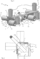
- a first embodiment of corner roller 100 according to the invention is illustrated in figures 3 and 4 in the salient angle rolling position of use.
- the angle roller 100 comprises a support 101 in the form of an angle iron having a first and a second wing 102-103 forming a non-flat angle between them, preferably a right angle.
- rollers are rotatably mounted perpendicular to the outer surface of the angle iron, and rollers are rotatably mounted perpendicular to the inner surface of the angle iron.
- the corner roller 100 comprises a first pair of rollers 110 rotatably mounted perpendicular to the outer surface 102a of the first wing 102 of the angle iron 101, and a second pair of rollers 111 rotatably mounted perpendicular to the outer surface 103a of the second flange 103 of the angle iron 101.
- the first and the second pair of rollers 110-111 in combination define a concave rolling surface 112.
- the corner roller 100 also comprises a third pair of rollers 120 rotatably mounted perpendicular to the inner surface 102b of the first wing 102 of the angle iron 101, and a fourth pair of rollers 121 rotatably mounted perpendicular to the inner surface 103b of the second wing 103 of the angle iron 101.
- the third and the fourth pair of rollers define in combination a convex rolling surface 122 (see figure 5 ).
- the angle iron 101 also has, pivotally fixed in the space (see arrows F1 and F2) between the inner surfaces 102b-103b of the two wings 102-103, a member 130 for fixing a handle 140 , and a window 104 facing the fixing member 130 for the passage of the handle 140 when it is fixed to the fixing member 130 in the re-entrant angle rolling position (see figures 5-6 ).
- the rollers 110 and 111 carried by the outer surfaces 102a-103a of the wings 102-103 of the angle iron 101, which are used to tighten the strips against a wall corner forming a salient angle.
- the handle is located on the side of the inner surfaces 102b-103b of the flanges 102-103 of the angle iron 101, and it is free to pivot relative to the angle iron 101 in the plane of the arrow F1, in the plane of the arrow F2 or in a combination of these two movements when using the angle roller by the user.
- the user separates the handle 140 from the fixing member 130, rotates the fixing member 130 in the plane of the arrow F1 towards the window 104 , then refixes the handle 140 on the fixing member 130 through the window 104 of the angle iron 101.
- the fixing member 130 of the handle 140 is rotatably mounted around a hinge pin 131 arranged between the inner surfaces 102b-103b of the two wings 102-103, and inside a space E delimited by the inner surfaces 102b-103b of the angle iron 101 and the convex rolling surface 122 delimited by the rollers 120-121 fixed to the inner surfaces 102b-103b of the angle iron 101, such that the fixing 130 is always inscribed in space E when the handle is fixed, in the re-entrant angle rolling position, to the fixing member 130 and it passes through the window 104.
- the fixing member 130 never exceeds the space E between the convex rolling surface 122 and the inner surfaces 102b-103b of the wings 102-103 of the angle iron 101.
- the fixing member therefore does not interfere at any time with the tightening of the strips by the rollers 120-121 located inside the angle iron 101.
- the corner roller 100 comprises two lugs 105 for holding the hinge pin 131 of the fixing member 130, each extending from the inner surface 102b-103b of a wing 102-103 respectively, towards the interior space E delimited by the interior surfaces 102b-103b of the wings 102-103 of the angle iron 101 and the convex rolling surface 122 delimited by the rollers 120-121 fixed on the inner surfaces 102b-103b of the wings 102-103 of the angle iron 101.
- these retaining tabs 105 have a length, measured from their point of connection to the wings of the angle iron, as they are listed in the volume E, that is to say that neither they nor the body of fixing 130 do not protrude from the volume E nor do they protrude into the convex rolling surface 122 when the handle is fixed in the re-entrant angle rolling position on the fixing member.
- the fixing member 130 of the handle 140 comprises a ball joint 132 for pivoting fixing to the axis of rotation 131 mounted between the lugs 105 for holding.
- This ball joint allows the handle to be able to pivot in space to facilitate the movement of the user who can place himself as he wishes with respect to the corner of the wall on which he must tighten a band.
- the fixing member 130 of the handle comprises an elongated junction piece 133 having a free end provided with means 134 for reversibly engaging the handle 140.
- It may be, for example, a spring-loaded pin 134 intended to engage in a locking orifice 141 carried by the handle 140.
- the retaining lugs 105 can be attached and welded (by fusion or gluing for example) to the inner surfaces 102b-103b of the wings 102-103 of the angle iron 101, opposite the window 104, c that is to say so that the fixing member 130 can pivot and be secured to the handle through the window 104.
- the retaining lugs 105 can form an integral part of the angle iron and be obtained by stamping and bending a part of the angle iron along the window, for example when hollowing out the window in the angle iron. What matters, of course, it is that these tabs 105 extend in space E, and not outwards as in the prior art, and that they are inscribed in this space E.
- the handle fixing member itself comprises a reversible engagement means of the handle. It may be a spring-loaded pin, as in the first embodiment, or as illustrated in figure 7 , a releasable circlip system.
- the fixing member 230 of the handle 240 comprises an orifice 231 provided with a releasable circlip 232 by an actuating means (not shown), and the handle 240 comprises a cylindrical end 241 intended to be inserted into the orifice 231, the cylindrical end 241 comprising a groove 242 for receiving the circlip 232.
- any means of reversible fixing of the handle can be used, such as for example a system for screwing the handle into or on the fastener 130-230.
- the window is shaped to allow pivoting of the handle relative to the angle iron facilitating the work of the user.
- the window 104 has a length L such that, seen in profile as in the figure 8 , the angle ⁇ formed between a first longitudinal end 104a of the window, a center of rotation C of the fastening member, and a second longitudinal end 104b of the window is between 110° and 150°. This allows a large range of movement of the handle relative to the angle, useful for example for very high walls.
- the angle a formed between a first longitudinal end 104a of the window, a center of rotation C of the fixing member, and a second end longitudinal 104b of the window is preferably between 120° and 140°, advantageously between 125° and 135°. This allows enough material to be left in the angle iron to have a rigid tool, while leaving a wide range of movement compatible with the vast majority of wall heights.
- the angle roller according to the invention can be marketed in the form of a smoothing assembly comprising one or more handles, for example of different or telescopic lengths, and an angle roller according to the invention.
- the corner roller according to the invention has a structure that can be adapted to two positions of use: one suitable for a re-entrant angle, the other suitable for an outgoing angle.
- This structure is robust since the wings of the angle iron are not hinged to one another.
- maintenance is easy, because plaster soiling does not prevent the change of position.
- the parts used for the design of the tool are few in number and resistant, so that the angle roller according to the invention is inexpensive and easy to use and maintain.
Landscapes
- Engineering & Computer Science (AREA)
- Architecture (AREA)
- Civil Engineering (AREA)
- Structural Engineering (AREA)
- Bending Of Plates, Rods, And Pipes (AREA)
- Pivots And Pivotal Connections (AREA)
- Metal Rolling (AREA)
Applications Claiming Priority (1)
| Application Number | Priority Date | Filing Date | Title |
|---|---|---|---|
| FR2110504A FR3127773B1 (fr) | 2021-10-05 | 2021-10-05 | Rouleur d’angle bi-fonction. |
Publications (2)
| Publication Number | Publication Date |
|---|---|
| EP4163460A1 true EP4163460A1 (de) | 2023-04-12 |
| EP4163460B1 EP4163460B1 (de) | 2025-09-17 |
Family
ID=78483394
Family Applications (1)
| Application Number | Title | Priority Date | Filing Date |
|---|---|---|---|
| EP22199148.2A Active EP4163460B1 (de) | 2021-10-05 | 2022-09-30 | Bifunktioneller eckroller |
Country Status (2)
| Country | Link |
|---|---|
| EP (1) | EP4163460B1 (de) |
| FR (1) | FR3127773B1 (de) |
Citations (2)
| Publication number | Priority date | Publication date | Assignee | Title |
|---|---|---|---|---|
| US6450232B1 (en) * | 2000-04-06 | 2002-09-17 | Timothy D. Smythe, Jr. | Drywall finishing roller and edge finisher |
| US9938731B1 (en) | 2016-02-11 | 2018-04-10 | Columbia Taping Tools, Ltd. | Inside-outside roller for structural corner bend |
-
2021
- 2021-10-05 FR FR2110504A patent/FR3127773B1/fr active Active
-
2022
- 2022-09-30 EP EP22199148.2A patent/EP4163460B1/de active Active
Patent Citations (2)
| Publication number | Priority date | Publication date | Assignee | Title |
|---|---|---|---|---|
| US6450232B1 (en) * | 2000-04-06 | 2002-09-17 | Timothy D. Smythe, Jr. | Drywall finishing roller and edge finisher |
| US9938731B1 (en) | 2016-02-11 | 2018-04-10 | Columbia Taping Tools, Ltd. | Inside-outside roller for structural corner bend |
Also Published As
| Publication number | Publication date |
|---|---|
| EP4163460B1 (de) | 2025-09-17 |
| FR3127773A1 (fr) | 2023-04-07 |
| FR3127773B1 (fr) | 2023-09-01 |
Similar Documents
| Publication | Publication Date | Title |
|---|---|---|
| CH716404B1 (fr) | Outil convertible a simple action entre un mode couteau tout usage et un mode grattoir. | |
| EP0275809A1 (de) | Lehre zum Zuschneiden von Fussbodenfliesen oder dergleichen | |
| FR2873951A1 (fr) | Couteau repliable | |
| FR2472451A1 (fr) | Manche de rasoir pourvu d'un dispositif de verrouillage pour cartouches pivotantes | |
| EP1961531A1 (de) | Befestigungsvorrichtung mit versenkbarem Handhebel und Geräte eine solche Vorrichtung enthaltend | |
| EP3980609A1 (de) | Auftragskopf für einen bandapplikator, mit einem solchen kopf versehener bandapplikator | |
| EP4163460B1 (de) | Bifunktioneller eckroller | |
| EP3976904B1 (de) | Streifenapplikator mit automatischer streifenanordnung während des füllvorgangs und verfahren zum befüllen eines solchen applikators | |
| EP3976902B1 (de) | Streifenapplikator mit einstellbarem beschichtungsfluss und verfahren zum einstellen des beschichtungsflusses eines solchen applikators | |
| FR2939347A1 (fr) | Ote-agrafe combine a une agrafeuse | |
| FR3096706A1 (fr) | Tête d’application pour un applicateur de bande, applicateur de bande muni d’une telle tête | |
| WO2007107669A2 (fr) | Treteau repliable | |
| EP0020268A1 (de) | Faltbarer und verpackbarer Toilettartikel, z.B. Zahnbürste | |
| EP2853186B1 (de) | Vorrichtung, die einen Reinigungskopf und ein Kippsystem zwischen zwei Oberflächen umfasst | |
| EP2839929B1 (de) | Einspannvorrichtung vom Typ Schraubzwinge | |
| WO2001051274A2 (fr) | Plieuse notamment pour flan plat | |
| FR2699568A1 (fr) | Boîte pliable pour le ramassage des déjections canines. | |
| FR2774619A1 (fr) | Couteau de ceinture pliant a fixation et blocage magnetique | |
| EP0935271B1 (de) | Scharnierdeckel insbesonderes für Schalterabdeckung | |
| CH656319A5 (fr) | Fixation de securite pour ski. | |
| FR2891298A1 (fr) | Arret de volet comportant un blocage reglable | |
| EP1605130A1 (de) | Fingerschutz | |
| FR2549124A1 (fr) | Charniere a systeme de rappel incorpore et organe quelconque equipe de cette charniere | |
| FR2926840A1 (fr) | Systeme de trappe d'acces, destine a permettre un acces a travers un mur ou plafond | |
| FR3022514A1 (fr) | Ensemble d’essuyage d’une vitre de vehicule automobile comportant une tete de montage et un bras d’entrainement |
Legal Events
| Date | Code | Title | Description |
|---|---|---|---|
| PUAI | Public reference made under article 153(3) epc to a published international application that has entered the european phase |
Free format text: ORIGINAL CODE: 0009012 |
|
| STAA | Information on the status of an ep patent application or granted ep patent |
Free format text: STATUS: THE APPLICATION HAS BEEN PUBLISHED |
|
| AK | Designated contracting states |
Kind code of ref document: A1 Designated state(s): AL AT BE BG CH CY CZ DE DK EE ES FI FR GB GR HR HU IE IS IT LI LT LU LV MC MK MT NL NO PL PT RO RS SE SI SK SM TR |
|
| P01 | Opt-out of the competence of the unified patent court (upc) registered |
Effective date: 20230509 |
|
| STAA | Information on the status of an ep patent application or granted ep patent |
Free format text: STATUS: REQUEST FOR EXAMINATION WAS MADE |
|
| 17P | Request for examination filed |
Effective date: 20230719 |
|
| RBV | Designated contracting states (corrected) |
Designated state(s): AL AT BE BG CH CY CZ DE DK EE ES FI FR GB GR HR HU IE IS IT LI LT LU LV MC MK MT NL NO PL PT RO RS SE SI SK SM TR |
|
| RAP1 | Party data changed (applicant data changed or rights of an application transferred) |
Owner name: EDMA |
|
| GRAP | Despatch of communication of intention to grant a patent |
Free format text: ORIGINAL CODE: EPIDOSNIGR1 |
|
| STAA | Information on the status of an ep patent application or granted ep patent |
Free format text: STATUS: GRANT OF PATENT IS INTENDED |
|
| INTG | Intention to grant announced |
Effective date: 20241213 |
|
| GRAJ | Information related to disapproval of communication of intention to grant by the applicant or resumption of examination proceedings by the epo deleted |
Free format text: ORIGINAL CODE: EPIDOSDIGR1 |
|
| STAA | Information on the status of an ep patent application or granted ep patent |
Free format text: STATUS: REQUEST FOR EXAMINATION WAS MADE |
|
| INTC | Intention to grant announced (deleted) | ||
| GRAP | Despatch of communication of intention to grant a patent |
Free format text: ORIGINAL CODE: EPIDOSNIGR1 |
|
| STAA | Information on the status of an ep patent application or granted ep patent |
Free format text: STATUS: GRANT OF PATENT IS INTENDED |
|
| INTG | Intention to grant announced |
Effective date: 20250516 |
|
| GRAS | Grant fee paid |
Free format text: ORIGINAL CODE: EPIDOSNIGR3 |
|
| GRAA | (expected) grant |
Free format text: ORIGINAL CODE: 0009210 |
|
| STAA | Information on the status of an ep patent application or granted ep patent |
Free format text: STATUS: THE PATENT HAS BEEN GRANTED |
|
| AK | Designated contracting states |
Kind code of ref document: B1 Designated state(s): AL AT BE BG CH CY CZ DE DK EE ES FI FR GB GR HR HU IE IS IT LI LT LU LV MC MK MT NL NO PL PT RO RS SE SI SK SM TR |
|
| REG | Reference to a national code |
Ref country code: GB Ref legal event code: FG4D Free format text: NOT ENGLISH |
|
| REG | Reference to a national code |
Ref country code: CH Ref legal event code: EP |
|
| REG | Reference to a national code |
Ref country code: DE Ref legal event code: R096 Ref document number: 602022021500 Country of ref document: DE |
|
| REG | Reference to a national code |
Ref country code: IE Ref legal event code: FG4D Free format text: LANGUAGE OF EP DOCUMENT: FRENCH |
|
| PGFP | Annual fee paid to national office [announced via postgrant information from national office to epo] |
Ref country code: DE Payment date: 20250916 Year of fee payment: 4 |
|
| PGFP | Annual fee paid to national office [announced via postgrant information from national office to epo] |
Ref country code: FR Payment date: 20250930 Year of fee payment: 4 |
|
| PG25 | Lapsed in a contracting state [announced via postgrant information from national office to epo] |
Ref country code: NO Free format text: LAPSE BECAUSE OF FAILURE TO SUBMIT A TRANSLATION OF THE DESCRIPTION OR TO PAY THE FEE WITHIN THE PRESCRIBED TIME-LIMIT Effective date: 20251217 |
|
| REG | Reference to a national code |
Ref country code: LT Ref legal event code: MG9D |
|
| PG25 | Lapsed in a contracting state [announced via postgrant information from national office to epo] |
Ref country code: FI Free format text: LAPSE BECAUSE OF FAILURE TO SUBMIT A TRANSLATION OF THE DESCRIPTION OR TO PAY THE FEE WITHIN THE PRESCRIBED TIME-LIMIT Effective date: 20250917 |
|
| PG25 | Lapsed in a contracting state [announced via postgrant information from national office to epo] |
Ref country code: HR Free format text: LAPSE BECAUSE OF FAILURE TO SUBMIT A TRANSLATION OF THE DESCRIPTION OR TO PAY THE FEE WITHIN THE PRESCRIBED TIME-LIMIT Effective date: 20250917 |
|
| PG25 | Lapsed in a contracting state [announced via postgrant information from national office to epo] |
Ref country code: GR Free format text: LAPSE BECAUSE OF FAILURE TO SUBMIT A TRANSLATION OF THE DESCRIPTION OR TO PAY THE FEE WITHIN THE PRESCRIBED TIME-LIMIT Effective date: 20251218 |
|
| PG25 | Lapsed in a contracting state [announced via postgrant information from national office to epo] |
Ref country code: SE Free format text: LAPSE BECAUSE OF FAILURE TO SUBMIT A TRANSLATION OF THE DESCRIPTION OR TO PAY THE FEE WITHIN THE PRESCRIBED TIME-LIMIT Effective date: 20250917 |
|
| REG | Reference to a national code |
Ref country code: NL Ref legal event code: MP Effective date: 20250917 |
|
| PG25 | Lapsed in a contracting state [announced via postgrant information from national office to epo] |
Ref country code: LV Free format text: LAPSE BECAUSE OF FAILURE TO SUBMIT A TRANSLATION OF THE DESCRIPTION OR TO PAY THE FEE WITHIN THE PRESCRIBED TIME-LIMIT Effective date: 20250917 |
|
| PG25 | Lapsed in a contracting state [announced via postgrant information from national office to epo] |
Ref country code: BG Free format text: LAPSE BECAUSE OF FAILURE TO SUBMIT A TRANSLATION OF THE DESCRIPTION OR TO PAY THE FEE WITHIN THE PRESCRIBED TIME-LIMIT Effective date: 20250917 |
|
| PG25 | Lapsed in a contracting state [announced via postgrant information from national office to epo] |
Ref country code: RS Free format text: LAPSE BECAUSE OF FAILURE TO SUBMIT A TRANSLATION OF THE DESCRIPTION OR TO PAY THE FEE WITHIN THE PRESCRIBED TIME-LIMIT Effective date: 20251217 |
|
| PG25 | Lapsed in a contracting state [announced via postgrant information from national office to epo] |
Ref country code: NL Free format text: LAPSE BECAUSE OF FAILURE TO SUBMIT A TRANSLATION OF THE DESCRIPTION OR TO PAY THE FEE WITHIN THE PRESCRIBED TIME-LIMIT Effective date: 20250917 |
|
| REG | Reference to a national code |
Ref country code: AT Ref legal event code: MK05 Ref document number: 1838390 Country of ref document: AT Kind code of ref document: T Effective date: 20250917 |
|
| PG25 | Lapsed in a contracting state [announced via postgrant information from national office to epo] |
Ref country code: SM Free format text: LAPSE BECAUSE OF FAILURE TO SUBMIT A TRANSLATION OF THE DESCRIPTION OR TO PAY THE FEE WITHIN THE PRESCRIBED TIME-LIMIT Effective date: 20250917 |
|
| PG25 | Lapsed in a contracting state [announced via postgrant information from national office to epo] |
Ref country code: ES Free format text: LAPSE BECAUSE OF FAILURE TO SUBMIT A TRANSLATION OF THE DESCRIPTION OR TO PAY THE FEE WITHIN THE PRESCRIBED TIME-LIMIT Effective date: 20250917 |
|
| PG25 | Lapsed in a contracting state [announced via postgrant information from national office to epo] |
Ref country code: AT Free format text: LAPSE BECAUSE OF FAILURE TO SUBMIT A TRANSLATION OF THE DESCRIPTION OR TO PAY THE FEE WITHIN THE PRESCRIBED TIME-LIMIT Effective date: 20250917 |
|
| PG25 | Lapsed in a contracting state [announced via postgrant information from national office to epo] |
Ref country code: IT Free format text: LAPSE BECAUSE OF FAILURE TO SUBMIT A TRANSLATION OF THE DESCRIPTION OR TO PAY THE FEE WITHIN THE PRESCRIBED TIME-LIMIT Effective date: 20250917 Ref country code: RO Free format text: LAPSE BECAUSE OF FAILURE TO SUBMIT A TRANSLATION OF THE DESCRIPTION OR TO PAY THE FEE WITHIN THE PRESCRIBED TIME-LIMIT Effective date: 20250917 |
|
| PG25 | Lapsed in a contracting state [announced via postgrant information from national office to epo] |
Ref country code: IS Free format text: LAPSE BECAUSE OF FAILURE TO SUBMIT A TRANSLATION OF THE DESCRIPTION OR TO PAY THE FEE WITHIN THE PRESCRIBED TIME-LIMIT Effective date: 20260117 |
|
| PG25 | Lapsed in a contracting state [announced via postgrant information from national office to epo] |
Ref country code: PT Free format text: LAPSE BECAUSE OF FAILURE TO SUBMIT A TRANSLATION OF THE DESCRIPTION OR TO PAY THE FEE WITHIN THE PRESCRIBED TIME-LIMIT Effective date: 20260119 Ref country code: CZ Free format text: LAPSE BECAUSE OF FAILURE TO SUBMIT A TRANSLATION OF THE DESCRIPTION OR TO PAY THE FEE WITHIN THE PRESCRIBED TIME-LIMIT Effective date: 20250917 |
|
| PG25 | Lapsed in a contracting state [announced via postgrant information from national office to epo] |
Ref country code: PL Free format text: LAPSE BECAUSE OF FAILURE TO SUBMIT A TRANSLATION OF THE DESCRIPTION OR TO PAY THE FEE WITHIN THE PRESCRIBED TIME-LIMIT Effective date: 20250917 |
|
| PG25 | Lapsed in a contracting state [announced via postgrant information from national office to epo] |
Ref country code: EE Free format text: LAPSE BECAUSE OF FAILURE TO SUBMIT A TRANSLATION OF THE DESCRIPTION OR TO PAY THE FEE WITHIN THE PRESCRIBED TIME-LIMIT Effective date: 20250917 Ref country code: SK Free format text: LAPSE BECAUSE OF FAILURE TO SUBMIT A TRANSLATION OF THE DESCRIPTION OR TO PAY THE FEE WITHIN THE PRESCRIBED TIME-LIMIT Effective date: 20250917 |
|
| REG | Reference to a national code |
Ref country code: CH Ref legal event code: H13 Free format text: ST27 STATUS EVENT CODE: U-0-0-H10-H13 (AS PROVIDED BY THE NATIONAL OFFICE) Effective date: 20260504 |