EP4163505B1 - Ensemble et dispositif de caméra - Google Patents
Ensemble et dispositif de caméra Download PDFInfo
- Publication number
- EP4163505B1 EP4163505B1 EP21201970.7A EP21201970A EP4163505B1 EP 4163505 B1 EP4163505 B1 EP 4163505B1 EP 21201970 A EP21201970 A EP 21201970A EP 4163505 B1 EP4163505 B1 EP 4163505B1
- Authority
- EP
- European Patent Office
- Prior art keywords
- component
- socket
- holding member
- hollow holding
- assembly according
- Prior art date
- Legal status (The legal status is an assumption and is not a legal conclusion. Google has not performed a legal analysis and makes no representation as to the accuracy of the status listed.)
- Active
Links
Images




Classifications
-
- G—PHYSICS
- G03—PHOTOGRAPHY; CINEMATOGRAPHY; ANALOGOUS TECHNIQUES USING WAVES OTHER THAN OPTICAL WAVES; ELECTROGRAPHY; HOLOGRAPHY
- G03B—APPARATUS OR ARRANGEMENTS FOR TAKING PHOTOGRAPHS OR FOR PROJECTING OR VIEWING THEM; APPARATUS OR ARRANGEMENTS EMPLOYING ANALOGOUS TECHNIQUES USING WAVES OTHER THAN OPTICAL WAVES; ACCESSORIES THEREFOR
- G03B17/00—Details of cameras or camera bodies; Accessories therefor
- G03B17/56—Accessories
- G03B17/561—Support related camera accessories
-
- H—ELECTRICITY
- H04—ELECTRIC COMMUNICATION TECHNIQUE
- H04N—PICTORIAL COMMUNICATION, e.g. TELEVISION
- H04N23/00—Cameras or camera modules comprising electronic image sensors; Control thereof
- H04N23/50—Constructional details
-
- F—MECHANICAL ENGINEERING; LIGHTING; HEATING; WEAPONS; BLASTING
- F16—ENGINEERING ELEMENTS AND UNITS; GENERAL MEASURES FOR PRODUCING AND MAINTAINING EFFECTIVE FUNCTIONING OF MACHINES OR INSTALLATIONS; THERMAL INSULATION IN GENERAL
- F16B—DEVICES FOR FASTENING OR SECURING CONSTRUCTIONAL ELEMENTS OR MACHINE PARTS TOGETHER, e.g. NAILS, BOLTS, CIRCLIPS, CLAMPS, CLIPS OR WEDGES; JOINTS OR JOINTING
- F16B21/00—Means for preventing relative axial movement of a pin, spigot, shaft or the like and a member surrounding it; Stud-and-socket releasable fastenings
- F16B21/06—Releasable fastening devices with snap-action
- F16B21/08—Releasable fastening devices with snap-action in which the stud, pin, or spigot has a resilient part
- F16B21/082—Releasable fastening devices with snap-action in which the stud, pin, or spigot has a resilient part the stud, pin or spigot having two resilient parts on its opposite ends in order to connect two elements
-
- F—MECHANICAL ENGINEERING; LIGHTING; HEATING; WEAPONS; BLASTING
- F16—ENGINEERING ELEMENTS AND UNITS; GENERAL MEASURES FOR PRODUCING AND MAINTAINING EFFECTIVE FUNCTIONING OF MACHINES OR INSTALLATIONS; THERMAL INSULATION IN GENERAL
- F16B—DEVICES FOR FASTENING OR SECURING CONSTRUCTIONAL ELEMENTS OR MACHINE PARTS TOGETHER, e.g. NAILS, BOLTS, CIRCLIPS, CLAMPS, CLIPS OR WEDGES; JOINTS OR JOINTING
- F16B13/00—Dowels or other devices fastened in walls or the like by inserting them in holes made therein for that purpose
- F16B13/12—Separate metal or non-separate or non-metal dowel sleeves fastened by inserting the screw, nail or the like
- F16B13/124—Separate metal or non-separate or non-metal dowel sleeves fastened by inserting the screw, nail or the like fastened by inserting a threaded element, e.g. screw or bolt
-
- F—MECHANICAL ENGINEERING; LIGHTING; HEATING; WEAPONS; BLASTING
- F16—ENGINEERING ELEMENTS AND UNITS; GENERAL MEASURES FOR PRODUCING AND MAINTAINING EFFECTIVE FUNCTIONING OF MACHINES OR INSTALLATIONS; THERMAL INSULATION IN GENERAL
- F16M—FRAMES, CASINGS OR BEDS OF ENGINES, MACHINES OR APPARATUS, NOT SPECIFIC TO ENGINES, MACHINES OR APPARATUS PROVIDED FOR ELSEWHERE; STANDS; SUPPORTS
- F16M13/00—Other supports for positioning apparatus or articles; Means for steadying hand-held apparatus or articles
- F16M13/02—Other supports for positioning apparatus or articles; Means for steadying hand-held apparatus or articles for supporting on, or attaching to, an object, e.g. tree, gate, window-frame, cycle
-
- G—PHYSICS
- G03—PHOTOGRAPHY; CINEMATOGRAPHY; ANALOGOUS TECHNIQUES USING WAVES OTHER THAN OPTICAL WAVES; ELECTROGRAPHY; HOLOGRAPHY
- G03B—APPARATUS OR ARRANGEMENTS FOR TAKING PHOTOGRAPHS OR FOR PROJECTING OR VIEWING THEM; APPARATUS OR ARRANGEMENTS EMPLOYING ANALOGOUS TECHNIQUES USING WAVES OTHER THAN OPTICAL WAVES; ACCESSORIES THEREFOR
- G03B17/00—Details of cameras or camera bodies; Accessories therefor
- G03B17/02—Bodies
-
- F—MECHANICAL ENGINEERING; LIGHTING; HEATING; WEAPONS; BLASTING
- F16—ENGINEERING ELEMENTS AND UNITS; GENERAL MEASURES FOR PRODUCING AND MAINTAINING EFFECTIVE FUNCTIONING OF MACHINES OR INSTALLATIONS; THERMAL INSULATION IN GENERAL
- F16B—DEVICES FOR FASTENING OR SECURING CONSTRUCTIONAL ELEMENTS OR MACHINE PARTS TOGETHER, e.g. NAILS, BOLTS, CIRCLIPS, CLAMPS, CLIPS OR WEDGES; JOINTS OR JOINTING
- F16B21/00—Means for preventing relative axial movement of a pin, spigot, shaft or the like and a member surrounding it; Stud-and-socket releasable fastenings
- F16B21/06—Releasable fastening devices with snap-action
- F16B21/08—Releasable fastening devices with snap-action in which the stud, pin, or spigot has a resilient part
- F16B21/086—Releasable fastening devices with snap-action in which the stud, pin, or spigot has a resilient part the shank of the stud, pin or spigot having elevations, ribs, fins or prongs intended for deformation or tilting predominantly in a direction perpendicular to the direction of insertion
-
- F—MECHANICAL ENGINEERING; LIGHTING; HEATING; WEAPONS; BLASTING
- F16—ENGINEERING ELEMENTS AND UNITS; GENERAL MEASURES FOR PRODUCING AND MAINTAINING EFFECTIVE FUNCTIONING OF MACHINES OR INSTALLATIONS; THERMAL INSULATION IN GENERAL
- F16B—DEVICES FOR FASTENING OR SECURING CONSTRUCTIONAL ELEMENTS OR MACHINE PARTS TOGETHER, e.g. NAILS, BOLTS, CIRCLIPS, CLAMPS, CLIPS OR WEDGES; JOINTS OR JOINTING
- F16B2200/00—Constructional details of connections not covered for in other groups of this subclass
- F16B2200/50—Flanged connections
- F16B2200/506—Flanged connections bolted or riveted
-
- F—MECHANICAL ENGINEERING; LIGHTING; HEATING; WEAPONS; BLASTING
- F16—ENGINEERING ELEMENTS AND UNITS; GENERAL MEASURES FOR PRODUCING AND MAINTAINING EFFECTIVE FUNCTIONING OF MACHINES OR INSTALLATIONS; THERMAL INSULATION IN GENERAL
- F16B—DEVICES FOR FASTENING OR SECURING CONSTRUCTIONAL ELEMENTS OR MACHINE PARTS TOGETHER, e.g. NAILS, BOLTS, CIRCLIPS, CLAMPS, CLIPS OR WEDGES; JOINTS OR JOINTING
- F16B5/00—Joining sheets or plates, e.g. panels, to one another or to strips or bars parallel to them
- F16B5/0004—Joining sheets, plates or panels in abutting relationship
- F16B5/0084—Joining sheets, plates or panels in abutting relationship characterised by particular locking means
- F16B5/0088—Joining sheets, plates or panels in abutting relationship characterised by particular locking means with locking means moving substantially perpendicular to the main plane, e.g. pins, screws
Definitions
- the present invention relates to an assembly and a camera device comprising such an assembly. More specifically, the invention relates to an assembly comprising a first component and a second component connected thereto.
- a device may comprise an assembly comprising a first and second component connectible to each other.
- the first component may be configured for mounting on a surface.
- the assembly may comprise means for temporarily holding the first and second component together in order to facilitate different steps of the installation, such as attaching of wirings. It is known to use different types of clips as means for temporarily holding the first and second component together.
- the installation may then be finished by securing the first and second component in an assembled state by means of threaded fasteners.
- An assembly is known from US 2018/009392 .
- the device comprising an assembly as described above may be a camera device, such as a surveillance camera.
- Surveillance cameras are commonly used to monitor objects or people within an area of surveillance by producing streams of video images that may be displayed to and/or recorded for use by security personnel.
- the surveillance cameras are often mounted many meters off the ground, to a wall, to a post structure or to a ceiling structure. This complicates the installation procedure for an installer of the surveillance camera.
- the installation personnel may need a scaffold or a ladder further complicating the handling of the surveillance camera.
- an assembly comprising a first component, a second component, a hollow holding member and a threaded fastener.
- the first component is connectable to the second component by means of the holding member and the threaded fastener.
- the first component has a first socket with a first socket opening and a threaded bore extending from a bottom surface of the first socket, and the second component has a second socket with a second socket opening.
- the first socket opening and the second socket opening are configured to face each other when the first and second component are connected to each other, wherein one of the first socket and the second socket is provided with an inlet restriction.
- the hollow holding member comprises a first portion arranged in the other one of the first socket and the second socket and connected to the associated first or second component.
- the hollow holding member comprises a second portion protruding from one of the first and second socket opening and is configured to be inserted into the second or first socket, respectively, via the other one of the first and second socket opening by relative movement of the first component towards the second component such that a top section of the second portion of the hollow holding member is passed by the inlet restriction under resilient deformation of the top section and/or the inlet restriction thereby achieving a connection between the first and second component.
- the threaded fastener is configured to extend through the hollow holding member from the second component to the threaded bore of the first socket of the first component for engagement with the threaded bore such that the connection between the first and second components is secured.
- the hollow holding member is supported by one of the first or second component and comprises a second portion which is insertable into the socket of the other one of the first or second component such that the top section of the second portion of the hollow holding member is passed by the inlet restriction under resilient deformation of the top section and/or the inlet restriction.
- the first and second component becomes releasable connected to each other, enabling an installer to perform different installation steps, such as attaching wires and the like, while the first and second component are releasable held together by means of the hollow holding member.
- the first and second component may be secured in their assembled state by means of the threaded fastener.
- the hollow holding member may be made of a resiliently deformable material.
- the hollow holding member may be made of a plastic material.
- the top section of the second portion of the hollow holding member may have a shape tapering towards a distal end of the top section.
- insertion of the second portion into the first or second socket and movement of the top section past the inlet restriction may be facilitated.
- the second portion of the hollow holding member may be provided with at least one slit extending in a longitudinal direction of the hollow holding member.
- the at least one slit in the second portion may provide the resilience required to ensure that the top section may be passed by the inlet restriction under resilient deformation of the top section.
- the first portion of the hollow holding member may be releasably connected to the first or second component.
- the first portion of the hollow holding member may be provided with a protruding, resilient lug and a side surface of the first or second socket may be provided with a recess, wherein the hollow holding member may be releasably connected to the first or second component by means of the protruding, resilient lug being received by the recess.
- the first portion of the hollow holding member may be releasably connected to the first or second component by means of a threaded joint.
- the first portion of the hollow holding member may be connected to the first or second component by means of an adhesive.
- the first or second socket may be provided with an internal guide surface extending between the first or second socket opening, respectively, and the inlet restriction such that an inlet passage is formed having a shape tapering towards the inlet restriction.
- an inlet passage is formed having a shape tapering towards the inlet restriction.
- the assembly may further comprise an additional component which is connectable to the first component by means of the treaded fastener with the second component intermediately arranged between the additional component and the first component.
- the second component By arranging the second component between the first component and the additional component, the second component may be clamped between the first component and the additional component by means of the threaded fastener.
- the inlet restriction may be integrally formed with the first or second component.
- the inlet restriction may be formed by a resilient member arranged in the first or second socket in proximity to the first or second socket opening, respectively.
- the resilient member may be formed as a separate piece.
- the resilient member may be a metal clip or an O-ring.
- the first component may comprise a base provided with a pillar structure with a distal end, wherein the first socket may be provided in the pillar structure with the first socket opening open to the distal end.
- the first component and/or the second component may be made of a plastic or a metallic material.
- a camera device comprising an assembly in accordance with what has been described above.
- a camera device 1 comprises an assembly 2 comprising a first component 3 and a second component 4 which are connected to each other by means of a hollow holding member 5 (shown in Fig. 2 ) and a threaded fastener 6.
- the assembly may also, as illustrated in the shown embodiment, comprise an additional component 7 which is connected to the first component 3 with the second component 4 intermediately arranged between the additional component 7 and the first component 3.
- the first component 3 has a first socket 8 with a first socket opening 9 and a threaded bore 10 extending from a bottom surface of the first socket 8.
- the second component 4 has a second socket 11 with a second socket opening 12, wherein the first socket opening 9 and the second socket opening 12 are configured to face each other when the first and second component 3, 4 are connected to each other.
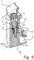
- the first socket 8 and the second socket 11 will be described more in detail below with reference to Fig. 5 .
- the first component 3 of the assembly 2 is a mount bracket and the second component 4 of the assembly 2 is camera unit.
- the mount bracket is configured for mounting on an installation surface.
- the camera unit comprises a camera body.
- the shown embodiment further comprises the additional component 7 in the form of a dome ring which is connected to the mount bracket with the camera unit arranged intermediately between the dome ring and the mount bracket.
- the camera device 1 may further comprise a dome window 13 which is attached to the assembly 2 by means of the dome ring.
- the dome ring and an external collar of the camera unit are made transparent in order to better illustrate the structure of the camera device 1.
- first component 3 and the second component 4 are connectible to each other by means of the hollow holding member 5 and the threaded fastener 6. More specifically, one of the first socket 8 and the second socket 11 is provided with an inlet restriction 14 and the hollow holding member 5 comprises a first portion 15, Fig.
- the hollow holding member 5 comprises a second portion 16 protruding from one of the first and second socket opening 9, 12 and configured to be inserted into the second or first socket 11, 8, respectively, via the other one of the first and second socket opening 9, 12 by relative movement of the first component 3 towards the second component 4 such that a top section 17 of the second portion 16 of the hollow holding member 5 is passed by the inlet restriction 14 under resilient deformation of the top section 17 and/or the inlet restriction 14 thereby achieving a connection between the first and second component 3, 4, which will be explained more in detail below.
- the threaded fastener 6 is configured to extend through the hollow holding member 5 from the second component 4 to the threaded bore 10 of the first socket 8 of the first component 3 for engagement with the threaded bore 10 such that the connection between the first and second components 3, 4 is secured.
- Fig. 2 the first component 3 in the form of a mount bracket is illustrated.
- the first component 3 forms a base provided with four pillar structures 18 circumferentially distributed along the peripheral portion of the first component 3.
- Each pillar structure 3 may be provided with a first socket 8 of the type as described above.
- Each pillar structure 18 has a distal end 19, wherein the first socket 8 is provided in the pillar structure 18 with the first socket opening 9 open to the distal end 19.
- two of the pillar structures 18 are associated with a hollow holding member 5.
- Each hollow holding member 5 comprises as described above, a first portion 15 and a second portion 16.
- the first portion 15 of each hollow holding member 5 is arranged in an associated first socket 8 and connected to the first component 3 while the second portion 16 protrudes from the first socket opening 9.
- the hollow holding member 5 and a pillar structure 18 provided with a first socket 8 accommodating the first portion 15 of the holding member 5 is shown in detail in Figs. 3 and 4 , to which reference now also is made.
- the hollow holding member 5 may be made of a plastic material.
- the hollow holding member 5 comprises a cylindrical body defining a channel extending in the longitudinal direction of the holding member 5.
- the lower part of the cylindrical body forms the first portion 15 of the holding member 5.
- a protrusion in the form of a resilient lug 20 is arranged on the first portion 15 projecting from the envelope surface of the body.
- the lug 20 is displaceable in a radial direction such that the first portion 15 of the holding member 5 may be inserted into the first socket 8.
- a side surface of the first socket 8 may be provided with a recess 21 configured to receive the lug 20 when the first portion 15 of the hollow holding member 5 is inserted into the first socket 8 such that the hollow holding member 5 may be releasable connected to the first component 3.
- the upper part of the cylindrical body forms the second portion 16 of the hollow holding member 5.
- the second portion comprises a top section 17 in the shape of a bulb.
- the bulb is tapering towards a distal end of the top section 17.
- the hollow holding member 5 may be provided with at least one slit 22 extending in the longitudinal direction of the hollow holding member 5. In the shown embodiment, the hollow holding member 5 is provided with three slits 22.
- the top section 17 of the second portion 16 of the hollow holding member 5 is configured such that it may, as explained above, be passed by the inlet restriction 14 under resilient deformation.
- the resilient deformation is enabled by means of the slits 22.
- FIG. 5 a cross sectional view is shown illustrating the assembly 2 of the type described above in an assembled state
- first component 3 and the second component 4 are connected to each other by means of the hollow holding member 5 and the connection is secured by means of the threaded fastener 6.
- the first and the second components 3, 4 are such arranged that the first socket opening 9 of the first socket faces 8 the second socket opening 12 of the second socket 11.
- the first portion 15 of the hollow holding member 5 is arranged in the first socket 8 and is releasably connected to the first component 3 by means of the resilient lug 20 received by the recess of 21 the first socket 8.
- the second portion 16 of the hollow holding member 5 protrudes from the first socket 8 and has been received by the second socket 11 via the second socket opening 12.
- the inlet restriction 14 of the second socket 11 is integrally formed with the second component 4.
- the inlet restriction 14 is arranged at a distance from the second socket opening 12 and the second socket 11 is provided with an internal guide surface 23 extending between the second socket opening 12 and the inlet restriction 14 such that an inlet passage is formed having a shape tapering towards the inlet restriction 14.
- the inlet restriction 14 has a width W1 essentially corresponding to a width W2 of the body of the hollow holding member 5.
- the top section 17 of the second portion 16 of the hollow holding member 5 has a width W3 which is greater than the width W1 of the inlet restriction 14.
- the top section 17 of the second portion 16 of the hollow holding member 5 has in the shown assembled state been passed by the inlet restriction 14 by relative movement of the first component 3 towards the second component 4.
- the top section 17 is as explained above configured for resilient deformation when passed by the inlet restriction 14.
- the internal guide surface of 23 the second socket 11 and the tapering shape of the top section 17 formed as a bulb will facilitate the resilient deformation.
- the top section will resume its original shape, thereby releasable connecting the first and second components 3, 4.
- the first and second components 2, 3 may be releasable connected to each other by means of the hollow holding member 5.
- the hollow holding member 5 enables a simple and sufficiently reliable connection of the first and second component 3, 4 during installation.
- the connection may be secured by means of the threaded fastener 6.
- a threaded fastener 6 in the form a screw is illustrated securing the connection of the first and second component 3, 4.
- the threaded fastener 6 extends through the hollow holding member 5 from the second socket 11 to the threaded bore 10 of the first socket 8 for engagement therewith.
- the assembly 2 further comprises an additional component 7 in the form of a dome ring, wherein the second component 4 is arranged between the first component 3 and the additional component 7, and the threaded fastener 6 extends from the additional component 7 such that the additional component 7, the second component 4 and the first component 3 are secured in the assembled state.
- FIG. 6 an alternative embodiment of an assembly 2 for a camera device 1 is shown, comprising a first component 3 in the form of a mount bracket, a second component 4 in the form of a camera unit and an additional component 7 in the form of a dome ring.
- the dome ring is connected to the mount bracket by means of a threaded fastener 6 with the camera unit arranged therebetween.
- the first component 3 and the second component 4 are releasable connected to each other by means of a hollow holding member 5, wherein the threaded fastener 6 extends through the hollow holding member 5 from the additional component 7 to the first component 3 via the second component 4.
- the hollow holding member 5 comprises a cylindrical body provided with a top section 17 formed as a bulb.
- a lower part of the cylindrical body forms the first portion 15 of the holding member 5, which first portion 15 is arranged in the first socket 8 of the first component 3 and connected to the first component 3 by means of an adhesive.
- the first portion may be connected to the first component by means of a thread.
- the second portion 16 of the hollow holding member 5 protrudes from the first socket opening 9 and extend into the second socket 11 of the second component 4.
- the top section 17 of the second portion 16 has been passed by an inlet restriction 14 of the second socket 11, which inlet restriction 14 is formed by a resilient member 24 arranged in the second socket 11 in proximity to the second socket opening 12.
- the resilient member 24 is clip made of for instance string steel.
- the clip which is shown in detail in Fig 7 defines a width W4 which is smaller than a width W3 of the top section 17 of the hollow holding member 5.
- the clip is configured for resilient deformation in response to the top section 17 being passed by the inlet restriction 14 by means of relative movement of the first component 3 towards the second component 4. When the top section 17 has been passed by the inlet restriction 14, the clip will resume its original form thereby releasably connect the second component 4 to the first component 3.
- the resilient member 24 may be formed by a O-ring as shown in Fig. 8 .
- the first portion of the hollow holding member is disclosed as being arranged in the first socket and connected to the first component. Further the second portion of the hollow holding member is disclosed as protruding from the first socket and inserted into the second socket via the second socket opening such that the top section is passed by the inlet restriction of the second socket under resilient deformation of the top section or the inlet restriction.
- the inlet restriction may be arranged in the first socket such that the second portion of the hollow holding member is insertable into the first socket via the first socket opening.
- the top section of the hollow holding member may be passed by the inlet restriction arranged in the first socket under resilient deformation of the top section and/or the inlet restriction for achieving the connection between the first and second component.
Landscapes
- Engineering & Computer Science (AREA)
- General Engineering & Computer Science (AREA)
- Mechanical Engineering (AREA)
- Physics & Mathematics (AREA)
- General Physics & Mathematics (AREA)
- Multimedia (AREA)
- Signal Processing (AREA)
- Connection Of Plates (AREA)
- Mutual Connection Of Rods And Tubes (AREA)
Claims (15)
- Ensemble comprenant un premier composant (3), un second composant (4), un élément de retenue creux (5) et une attache filetée (6),le premier composant (3) étant connectable au second composant (4) au moyen de l'élément de retenue creux (5) et de l'attache filetée (6),le premier composant (3) comportant une première douille (8) dotée d'une ouverture de première douille (9) et un trou fileté (10) s'étendant depuis une surface inférieure de la première douille (8),le second composant (4) comportant une seconde douille (11) doté d'une ouverture de seconde douille (12)l'ouverture de première douille (9) et l'ouverture de seconde douille (12) étant configurées pour se faire face lorsque les premier et second composants (3, 4) sont connectés l'un à l'autre,une parmi la première douille (8) et la seconde douille (11) étant pourvue d'un restricteur d'entrée (14),l'élément de retenue creux (5) comprenant une première section (15) disposée dans l'autre parmi la première douille (8) et la seconde douille (11) et connectée au premier ou second composant associé (3, 4),l'élément de retenue creux (5) comprenant une seconde section (16) saillant de l'une des première et seconde ouvertures de douille (9,10) et configurée pour être insérée dans la seconde ou première douille (11, 8) respectivement via l'autre de douille (9,12) par un mouvement relatif du premier composant (3) vers le second composant (4) de manière à ce qu'une section supérieure (17) de la seconde section (16) de l'élément de retenue creux (5) soit traversée par le restricteur d'entrée (14) sous déformation élastique de la section supérieure (17) et/ou du restricteur d'entrée (14), en établissant ainsi une connexion entre les premier et second composants (3, 4), etl'attache filetée (6) étant configurée pour s'étendre à travers l'élément de retenue creux (5) depuis le second composant (4) jusqu'au trou fileté (10) de la première douille (8) du premier composant (12) pour engagement avec le trou fileté (10) de manière à ce que la connexion entre les premier et second composants (3, 4) soit bloquée.
- Ensemble selon la revendication 1, dans lequel la section supérieure (17) de la seconde section (16) de l'élément de retenue creux (5) a une forme s'effilant vers une extrémité distale de la section supérieure (17).
- Ensemble selon la revendication 1 ou 2, dans lequel la seconde section (16) de l'élément de retenue creux (5) est pourvue d'au moins une fente (22) s'étendant dans un sens longitudinal de l'élément de retenue creux (5)
- Ensemble selon l'une quelconque des revendications 1 à 3, dans lequel la première section (15) de l'élément de retenue creux (5) est connectée de manière dissociable au premier ou second composant (3, 4).
- Ensemble selon la revendication 4, dans lequel la première section (15) de l'élément de retenue creux (5) est pourvue d'un ergot élastique saillant (20) et une surface latérale de la première ou seconde douille (8, 11) est pourvue d'un retrait (21), l'élément de retenue creux (5) étant connecté de manière dissociable au premier ou second composant (3, 4) au moyen de l'ergot élastique saillant (20) qui est reçu par le retrait (21).
- Ensemble selon la revendication 4, dans lequel la première section (15) de l'élément de retenue creux (5) est connectée de manière dissociable au premier ou second composant (3, 4) au moyen d'un joint fileté.
- Ensemble selon l'une quelconque des revendications 1 à 3, dans lequel la première section (15) de l'élément de retenue creux (5) est connectée au premier ou second composant (3, 4) au moyen d'une colle.
- Ensemble selon l'une quelconque des revendications précédentes, dans lequel la première ou seconde douille (8,11) est pourvue d'une surface de guidage interne (23) s'étendant entre l'ouverture de la première ou seconde douille (9,12) respectivement, et le restricteur d'entrée (14), de sorte qu'il est formé un passage d'entrée ayant une forme se rétrécissant vers le restricteur d'entrée (14).
- Ensemble selon l'une quelconque des revendications précédentes, comprenant en outre un composant supplémentaire (7) qui est connectable au premier composant (3) au moyen de l'attache filetée (6) avec le second composant (4) disposé de manière intermédiaire entre le composant supplémentaire (7) et le premier composant (3).
- Ensemble selon l'une quelconque des revendications précédentes, dans lequel le restricteur d'entrée (14) forme partie intégrante du premier ou second composant (3, 4).
- Ensemble selon l'une quelconque des revendications 1 à 9, dans lequel le restricteur d'entrée (14) est formé par un élément élastique (24) disposé dans la première ou seconde douille (8,11) à proximité de la première ou seconde ouverture de douille (9,12) respectivement.
- Ensemble selon la revendication 11, dans lequel l'élément élastique (24) est un clip métallique ou un joint torique.
- Ensemble selon l'une quelconque des revendications précédentes, dans lequel le premier composant (3) comprend une base pourvue d'une structure en forme de colonne (18) dotée d'une extrémité distale (19), la première douille (8) étant prévue dans la structure en forme de colonne (18) avec la première ouverture de douille (9) ouvrant sur l'extrémité distale (19).
- Ensemble selon l'une quelconque des revendications précédentes, dans lequel le premier composant (3) et/ou le second composant (4) est composé de matière plastique ou d'un matériau métallique.
- Dispositif de caméra comprenant un ensemble (2) selon l'une quelconque des revendications précédentes.
Priority Applications (4)
| Application Number | Priority Date | Filing Date | Title |
|---|---|---|---|
| EP21201970.7A EP4163505B1 (fr) | 2021-10-11 | 2021-10-11 | Ensemble et dispositif de caméra |
| KR1020220067440A KR102831895B1 (ko) | 2021-10-11 | 2022-06-02 | 어셈블리 및 카메라 장치 |
| US17/835,038 US12007676B2 (en) | 2021-10-11 | 2022-06-08 | Assembly and camera device |
| CN202210774305.2A CN115962211B (zh) | 2021-10-11 | 2022-07-01 | 组件和摄像机装置 |
Applications Claiming Priority (1)
| Application Number | Priority Date | Filing Date | Title |
|---|---|---|---|
| EP21201970.7A EP4163505B1 (fr) | 2021-10-11 | 2021-10-11 | Ensemble et dispositif de caméra |
Publications (3)
| Publication Number | Publication Date |
|---|---|
| EP4163505A1 EP4163505A1 (fr) | 2023-04-12 |
| EP4163505C0 EP4163505C0 (fr) | 2023-11-29 |
| EP4163505B1 true EP4163505B1 (fr) | 2023-11-29 |
Family
ID=78087202
Family Applications (1)
| Application Number | Title | Priority Date | Filing Date |
|---|---|---|---|
| EP21201970.7A Active EP4163505B1 (fr) | 2021-10-11 | 2021-10-11 | Ensemble et dispositif de caméra |
Country Status (4)
| Country | Link |
|---|---|
| US (1) | US12007676B2 (fr) |
| EP (1) | EP4163505B1 (fr) |
| KR (1) | KR102831895B1 (fr) |
| CN (1) | CN115962211B (fr) |
Family Cites Families (14)
| Publication number | Priority date | Publication date | Assignee | Title |
|---|---|---|---|---|
| JPS566906A (en) * | 1979-06-26 | 1981-01-24 | Nissan Motor | Fitting device for parts |
| DE9403481U1 (de) * | 1994-03-02 | 1995-06-29 | Müllenberg, Ralph, 41516 Grevenbroich | Spannanordnung mit einem Konusspannbolzen |
| JP4125012B2 (ja) * | 2002-01-25 | 2008-07-23 | ダイハツ工業株式会社 | クリップ |
| AT411785B (de) | 2003-02-05 | 2004-05-25 | Guenter Sikora | Lösbare schnappverbindung |
| JP4584893B2 (ja) | 2006-10-02 | 2010-11-24 | 池上通信機株式会社 | 天井埋め込み型カメラ取付機構 |
| JP5033149B2 (ja) * | 2009-02-10 | 2012-09-26 | パナソニック株式会社 | 監視カメラおよび監視カメラの取付け方法 |
| KR100959937B1 (ko) * | 2009-03-31 | 2010-05-26 | (주)파워텍일렉트로닉스 | 방수기능이 강화된 돔형 감시카메라 구조 |
| JP2013002498A (ja) * | 2011-06-14 | 2013-01-07 | Sony Corp | 保持部材 |
| US20130322985A1 (en) * | 2012-05-31 | 2013-12-05 | United Technologies Corporation | Retention assembly including sleeve |
| CN203847532U (zh) * | 2014-04-28 | 2014-09-24 | 恒昌行精密工业有限公司 | 旋动式固定装置 |
| US20180009392A1 (en) * | 2015-01-28 | 2018-01-11 | Fujitsu Ten Limited | Device for mounting audio speaker in vehicle and mounting construction thereof |
| CN205071148U (zh) | 2015-10-28 | 2016-03-02 | 杭州海康威视数字技术股份有限公司 | 一种全景拼接摄像机 |
| DE102016112014A1 (de) * | 2016-06-30 | 2018-01-04 | Böllhoff Verbindungstechnik GmbH | Befestiger mit Dämpfungsfunktion |
| FR3099809B1 (fr) * | 2019-08-07 | 2021-07-16 | A Raymond Et Cie | Dispositif de raccordement entre un élément tubulaire et une embase |
-
2021
- 2021-10-11 EP EP21201970.7A patent/EP4163505B1/fr active Active
-
2022
- 2022-06-02 KR KR1020220067440A patent/KR102831895B1/ko active Active
- 2022-06-08 US US17/835,038 patent/US12007676B2/en active Active
- 2022-07-01 CN CN202210774305.2A patent/CN115962211B/zh active Active
Also Published As
| Publication number | Publication date |
|---|---|
| US12007676B2 (en) | 2024-06-11 |
| CN115962211B (zh) | 2025-04-29 |
| EP4163505C0 (fr) | 2023-11-29 |
| KR102831895B1 (ko) | 2025-07-08 |
| KR20230051752A (ko) | 2023-04-18 |
| EP4163505A1 (fr) | 2023-04-12 |
| US20230116316A1 (en) | 2023-04-13 |
| CN115962211A (zh) | 2023-04-14 |
Similar Documents
| Publication | Publication Date | Title |
|---|---|---|
| USRE39448E1 (en) | Connecting device for connecting a fan blade to a rotor of a motor of a ceiling fan | |
| JPH0624269A (ja) | 点灯あるいは指示ユニットを、自動車に固定するための締結具 | |
| GB2196712A (en) | Captive panel fasteners | |
| EP4163505B1 (fr) | Ensemble et dispositif de caméra | |
| US5558480A (en) | Bolt for truss, wherein the bolt has shaft portions separated by a groove and a stopper having protrusions engaged in the groove | |
| WO2003023260A2 (fr) | Systeme de joint pour ensembles conduites de puits d'eau | |
| JP2001182724A (ja) | 室内装備取付ブラケット | |
| JP3393073B2 (ja) | マイクロホンの取付装置 | |
| JP3418263B2 (ja) | 合成樹脂製埋め込み配線ボックス | |
| JPH07249337A (ja) | グロメット | |
| JP3108379B2 (ja) | ダクト用口元 | |
| JP3626842B2 (ja) | スプリンクラーヘッドの固定装置 | |
| CN223204245U (zh) | 一种适配大开孔的筒灯安装结构和筒灯装置 | |
| CN219300460U (zh) | 嵌入式支架及具有其的监控设备 | |
| CN217880950U (zh) | 一种软排线固定组件 | |
| CA3266223C (fr) | Ensemble de cadre | |
| US7736082B1 (en) | Fastening system for assembling plastic units and rib clip therefor | |
| CN115324171B (zh) | 一种用于台面水龙头固定的连接组件及安装方法 | |
| KR200323020Y1 (ko) | 지지벽이 형성된 커넥터 커플링 | |
| JPH0631262Y2 (ja) | ガスコック用配管端末固定具 | |
| JP3112729B2 (ja) | 柱接続装置 | |
| JPH0776568B2 (ja) | 外装部品の取付方法 | |
| JPS5834791Y2 (ja) | 板状体等の二部材の取付け構造 | |
| JP3784237B2 (ja) | 支線取付具 | |
| JP3115192B2 (ja) | 挿口突部の形成方法およびその挿口を有した離脱防止管継手 |
Legal Events
| Date | Code | Title | Description |
|---|---|---|---|
| PUAI | Public reference made under article 153(3) epc to a published international application that has entered the european phase |
Free format text: ORIGINAL CODE: 0009012 |
|
| STAA | Information on the status of an ep patent application or granted ep patent |
Free format text: STATUS: REQUEST FOR EXAMINATION WAS MADE |
|
| 17P | Request for examination filed |
Effective date: 20220621 |
|
| AK | Designated contracting states |
Kind code of ref document: A1 Designated state(s): AL AT BE BG CH CY CZ DE DK EE ES FI FR GB GR HR HU IE IS IT LI LT LU LV MC MK MT NL NO PL PT RO RS SE SI SK SM TR |
|
| RIC1 | Information provided on ipc code assigned before grant |
Ipc: F16B 5/00 20060101ALN20230727BHEP Ipc: G08B 13/196 20060101ALI20230727BHEP Ipc: F16B 21/08 20060101AFI20230727BHEP |
|
| GRAP | Despatch of communication of intention to grant a patent |
Free format text: ORIGINAL CODE: EPIDOSNIGR1 |
|
| STAA | Information on the status of an ep patent application or granted ep patent |
Free format text: STATUS: GRANT OF PATENT IS INTENDED |
|
| INTG | Intention to grant announced |
Effective date: 20230914 |
|
| GRAS | Grant fee paid |
Free format text: ORIGINAL CODE: EPIDOSNIGR3 |
|
| GRAA | (expected) grant |
Free format text: ORIGINAL CODE: 0009210 |
|
| STAA | Information on the status of an ep patent application or granted ep patent |
Free format text: STATUS: THE PATENT HAS BEEN GRANTED |
|
| AK | Designated contracting states |
Kind code of ref document: B1 Designated state(s): AL AT BE BG CH CY CZ DE DK EE ES FI FR GB GR HR HU IE IS IT LI LT LU LV MC MK MT NL NO PL PT RO RS SE SI SK SM TR |
|
| REG | Reference to a national code |
Ref country code: GB Ref legal event code: FG4D |
|
| REG | Reference to a national code |
Ref country code: CH Ref legal event code: EP |
|
| REG | Reference to a national code |
Ref country code: DE Ref legal event code: R096 Ref document number: 602021007255 Country of ref document: DE |
|
| REG | Reference to a national code |
Ref country code: IE Ref legal event code: FG4D |
|
| U01 | Request for unitary effect filed |
Effective date: 20231129 |
|
| U07 | Unitary effect registered |
Designated state(s): AT BE BG DE DK EE FI FR IT LT LU LV MT NL PT SE SI Effective date: 20231205 |
|
| PG25 | Lapsed in a contracting state [announced via postgrant information from national office to epo] |
Ref country code: GR Free format text: LAPSE BECAUSE OF FAILURE TO SUBMIT A TRANSLATION OF THE DESCRIPTION OR TO PAY THE FEE WITHIN THE PRESCRIBED TIME-LIMIT Effective date: 20240301 |
|
| PG25 | Lapsed in a contracting state [announced via postgrant information from national office to epo] |
Ref country code: IS Free format text: LAPSE BECAUSE OF FAILURE TO SUBMIT A TRANSLATION OF THE DESCRIPTION OR TO PAY THE FEE WITHIN THE PRESCRIBED TIME-LIMIT Effective date: 20240329 |
|
| PG25 | Lapsed in a contracting state [announced via postgrant information from national office to epo] |
Ref country code: ES Free format text: LAPSE BECAUSE OF FAILURE TO SUBMIT A TRANSLATION OF THE DESCRIPTION OR TO PAY THE FEE WITHIN THE PRESCRIBED TIME-LIMIT Effective date: 20231129 |
|
| PG25 | Lapsed in a contracting state [announced via postgrant information from national office to epo] |
Ref country code: IS Free format text: LAPSE BECAUSE OF FAILURE TO SUBMIT A TRANSLATION OF THE DESCRIPTION OR TO PAY THE FEE WITHIN THE PRESCRIBED TIME-LIMIT Effective date: 20240329 Ref country code: GR Free format text: LAPSE BECAUSE OF FAILURE TO SUBMIT A TRANSLATION OF THE DESCRIPTION OR TO PAY THE FEE WITHIN THE PRESCRIBED TIME-LIMIT Effective date: 20240301 Ref country code: ES Free format text: LAPSE BECAUSE OF FAILURE TO SUBMIT A TRANSLATION OF THE DESCRIPTION OR TO PAY THE FEE WITHIN THE PRESCRIBED TIME-LIMIT Effective date: 20231129 |
|
| PG25 | Lapsed in a contracting state [announced via postgrant information from national office to epo] |
Ref country code: RS Free format text: LAPSE BECAUSE OF FAILURE TO SUBMIT A TRANSLATION OF THE DESCRIPTION OR TO PAY THE FEE WITHIN THE PRESCRIBED TIME-LIMIT Effective date: 20231129 Ref country code: PL Free format text: LAPSE BECAUSE OF FAILURE TO SUBMIT A TRANSLATION OF THE DESCRIPTION OR TO PAY THE FEE WITHIN THE PRESCRIBED TIME-LIMIT Effective date: 20231129 Ref country code: NO Free format text: LAPSE BECAUSE OF FAILURE TO SUBMIT A TRANSLATION OF THE DESCRIPTION OR TO PAY THE FEE WITHIN THE PRESCRIBED TIME-LIMIT Effective date: 20240229 Ref country code: HR Free format text: LAPSE BECAUSE OF FAILURE TO SUBMIT A TRANSLATION OF THE DESCRIPTION OR TO PAY THE FEE WITHIN THE PRESCRIBED TIME-LIMIT Effective date: 20231129 |
|
| PG25 | Lapsed in a contracting state [announced via postgrant information from national office to epo] |
Ref country code: CZ Free format text: LAPSE BECAUSE OF FAILURE TO SUBMIT A TRANSLATION OF THE DESCRIPTION OR TO PAY THE FEE WITHIN THE PRESCRIBED TIME-LIMIT Effective date: 20231129 |
|
| PG25 | Lapsed in a contracting state [announced via postgrant information from national office to epo] |
Ref country code: SK Free format text: LAPSE BECAUSE OF FAILURE TO SUBMIT A TRANSLATION OF THE DESCRIPTION OR TO PAY THE FEE WITHIN THE PRESCRIBED TIME-LIMIT Effective date: 20231129 |
|
| PG25 | Lapsed in a contracting state [announced via postgrant information from national office to epo] |
Ref country code: SM Free format text: LAPSE BECAUSE OF FAILURE TO SUBMIT A TRANSLATION OF THE DESCRIPTION OR TO PAY THE FEE WITHIN THE PRESCRIBED TIME-LIMIT Effective date: 20231129 Ref country code: SK Free format text: LAPSE BECAUSE OF FAILURE TO SUBMIT A TRANSLATION OF THE DESCRIPTION OR TO PAY THE FEE WITHIN THE PRESCRIBED TIME-LIMIT Effective date: 20231129 Ref country code: RO Free format text: LAPSE BECAUSE OF FAILURE TO SUBMIT A TRANSLATION OF THE DESCRIPTION OR TO PAY THE FEE WITHIN THE PRESCRIBED TIME-LIMIT Effective date: 20231129 Ref country code: CZ Free format text: LAPSE BECAUSE OF FAILURE TO SUBMIT A TRANSLATION OF THE DESCRIPTION OR TO PAY THE FEE WITHIN THE PRESCRIBED TIME-LIMIT Effective date: 20231129 |
|
| REG | Reference to a national code |
Ref country code: DE Ref legal event code: R097 Ref document number: 602021007255 Country of ref document: DE |
|
| PLBE | No opposition filed within time limit |
Free format text: ORIGINAL CODE: 0009261 |
|
| STAA | Information on the status of an ep patent application or granted ep patent |
Free format text: STATUS: NO OPPOSITION FILED WITHIN TIME LIMIT |
|
| U20 | Renewal fee for the european patent with unitary effect paid |
Year of fee payment: 4 Effective date: 20240919 |
|
| 26N | No opposition filed |
Effective date: 20240830 |
|
| REG | Reference to a national code |
Ref country code: CH Ref legal event code: PL |
|
| PG25 | Lapsed in a contracting state [announced via postgrant information from national office to epo] |
Ref country code: MC Free format text: LAPSE BECAUSE OF FAILURE TO SUBMIT A TRANSLATION OF THE DESCRIPTION OR TO PAY THE FEE WITHIN THE PRESCRIBED TIME-LIMIT Effective date: 20231129 |
|
| PG25 | Lapsed in a contracting state [announced via postgrant information from national office to epo] |
Ref country code: CH Free format text: LAPSE BECAUSE OF NON-PAYMENT OF DUE FEES Effective date: 20241031 |
|
| PGFP | Annual fee paid to national office [announced via postgrant information from national office to epo] |
Ref country code: GB Payment date: 20250923 Year of fee payment: 5 |
|
| PG25 | Lapsed in a contracting state [announced via postgrant information from national office to epo] |
Ref country code: IE Free format text: LAPSE BECAUSE OF NON-PAYMENT OF DUE FEES Effective date: 20241011 |
|
| U20 | Renewal fee for the european patent with unitary effect paid |
Year of fee payment: 5 Effective date: 20250923 |
|
| PG25 | Lapsed in a contracting state [announced via postgrant information from national office to epo] |
Ref country code: CY Free format text: LAPSE BECAUSE OF FAILURE TO SUBMIT A TRANSLATION OF THE DESCRIPTION OR TO PAY THE FEE WITHIN THE PRESCRIBED TIME-LIMIT; INVALID AB INITIO Effective date: 20211011 |
|
| PG25 | Lapsed in a contracting state [announced via postgrant information from national office to epo] |
Ref country code: HU Free format text: LAPSE BECAUSE OF FAILURE TO SUBMIT A TRANSLATION OF THE DESCRIPTION OR TO PAY THE FEE WITHIN THE PRESCRIBED TIME-LIMIT; INVALID AB INITIO Effective date: 20211011 |