EP4163732B1 - Kupplungsuhrmechanismus - Google Patents
Kupplungsuhrmechanismus Download PDFInfo
- Publication number
- EP4163732B1 EP4163732B1 EP22199695.2A EP22199695A EP4163732B1 EP 4163732 B1 EP4163732 B1 EP 4163732B1 EP 22199695 A EP22199695 A EP 22199695A EP 4163732 B1 EP4163732 B1 EP 4163732B1
- Authority
- EP
- European Patent Office
- Prior art keywords
- clutch
- wheel
- shaft
- rigid
- clutch disc
- Prior art date
- Legal status (The legal status is an assumption and is not a legal conclusion. Google has not performed a legal analysis and makes no representation as to the accuracy of the status listed.)
- Active
Links
Images



Classifications
-
- G—PHYSICS
- G04—HOROLOGY
- G04F—TIME-INTERVAL MEASURING
- G04F7/00—Apparatus for measuring unknown time intervals by non-electric means
- G04F7/04—Apparatus for measuring unknown time intervals by non-electric means using a mechanical oscillator
- G04F7/08—Watches or clocks with stop devices, e.g. chronograph
- G04F7/0823—Watches or clocks with stop devices, e.g. chronograph with couplings between the chronograph mechanism and the base movement
-
- G—PHYSICS
- G04—HOROLOGY
- G04B—MECHANICALLY-DRIVEN CLOCKS OR WATCHES; MECHANICAL PARTS OF CLOCKS OR WATCHES IN GENERAL; TIME PIECES USING THE POSITION OF THE SUN, MOON OR STARS
- G04B11/00—Click devices; Stop clicks; Clutches
- G04B11/001—Clutch mechanism between two rotating members with transfer of movement in both directions, possibly with limitation on the transfer of power
- G04B11/003—Clutch mechanism between two rotating members with transfer of movement in both directions, possibly with limitation on the transfer of power with friction member, e.g. with spring action
-
- G—PHYSICS
- G04—HOROLOGY
- G04F—TIME-INTERVAL MEASURING
- G04F7/00—Apparatus for measuring unknown time intervals by non-electric means
- G04F7/04—Apparatus for measuring unknown time intervals by non-electric means using a mechanical oscillator
- G04F7/08—Watches or clocks with stop devices, e.g. chronograph
- G04F7/0823—Watches or clocks with stop devices, e.g. chronograph with couplings between the chronograph mechanism and the base movement
- G04F7/0828—Watches or clocks with stop devices, e.g. chronograph with couplings between the chronograph mechanism and the base movement acting in the plane of the movement
Definitions
- the present invention relates to a clutch watch mechanism.
- the present invention also relates to a watch movement comprising such a mechanism, as well as a timepiece, for example a chronograph watch, in particular a wrist chronograph watch, comprising such a mechanism or such a movement.
- a chronograph watch in particular a wrist chronograph watch
- the mechanism according to the invention can be used to produce a clutch in a chronograph watch, it is not limited to such an application, but it can also be used for any other watchmaking application which requires a clutch: for example and in a non-limiting manner, it can be used in a striking watch mechanism.
- a chronograph watch is a timepiece that can measure time.
- a chronograph watch includes at least one indicator (such as a hand) that can be started and stopped by a pusher or other control element to measure time. It can then be returned to its starting point.
- Chronograph watches generally also include indicators for displaying the current time in addition to displaying the measured time.
- control devices can be, for example, cam or column wheel. Since they are known per se in the field of technology, they will not be described here.
- Clutch devices allow the chronograph drive train to be driven by the drive train for counting and displaying the current time.
- clutch devices allow the chronograph drive train to be started and stopped very quickly, and also to be locked while keeping the chronograph indicators stopped.
- Vertical clutch devices allow a so-called “vertical” clutch between the two drive trains, in particular between a wheel of one drive train and a wheel of the other drive train.
- Lateral or horizontal clutch devices allow two wheels to be coupled by bringing them into contact by their periphery, in particular by their teeth.
- the disadvantage of this type of clutch is that when driving the chronograph wheel it is possible to have a starting jump caused by a bad alignment of the teeth of the two wheels.
- the gap is all the smaller the more teeth there are.
- teeth with many teeth are difficult to manufacture and more subject to wear. In this type of device, there is no oscillating movement or tilting of the elements of these devices.
- oscillating pinion clutch devices which allow energy to be transmitted from one wheel of one drive train to a wheel of the other drive train using an oscillating pinion.
- This oscillating pinion has a first toothing which is in permanent contact with the wheel of the drive train which makes it possible to determine the current time.
- This oscillating pinion under the action of an actuating device such as a rocker, oscillates or rocks, so that its second toothing comes into contact with the wheel which makes it possible to measure a duration, thus also setting it in rotation.
- the clutch mechanism described is complex and comprises more than ten parts.
- the clutch disc is actuation indirectly and is done via pins.
- several contacts take place between the different components (drive plate ⁇ clutch elements ⁇ spring ⁇ disc ⁇ friction spring ⁇ ring ⁇ shaft), which results in a significant loss of energy.
- This clutch mechanism is complex, as it requires a clutch disc having elements arranged to pivot under the action of flexible blades and to accommodate pins that are perpendicular to the plane of the disc. Since these pins perform the clutch with the chronograph wheel, the friction surface between the chronograph wheel and each of these pins is small, which reduces the reliability of the clutch.
- the mechanism described includes several parts (clutch disc, several pins, etc.), which does not facilitate the assembly of the mechanism, in addition to complicating the mounting of the pins in the disc.
- An object of the present invention is to provide a clutch mechanism free from the limitations of known clutch mechanisms.
- Another object of the invention is to provide a clutch mechanism which comprises fewer components than known clutch mechanisms.
- Another object of the invention is to provide a clutch mechanism that is less bulky than known clutch mechanisms.
- Another object of the invention is to provide a clutch mechanism which is easier to mount than known clutch mechanisms.
- clutch disc (or second wheel) integral with the shaft indicates that the disc (or second wheel) and the shaft can be driven by each other in a common movement, without necessarily being fixed (e.g. directly fixed) to each other.
- a clutch disc frictionally connected to the shaft is also integral with the shaft.
- the clutch clock mechanism according to the invention is arranged to pass, under the action of the control device, from an engaged position to a disengaged position and vice versa.
- the first wheel drives the second wheel (the drive not necessarily being direct), and in the disengaged position the first wheel no longer drives the second wheel.
- the expression "flexible blade” means a blade or beam, arranged to deform elastically in the plane of the clutch disc, for example in a bending movement.
- the expression "rigid clutch elements” designates parts of the clutch disc which are not intended to be deformed during operation of the mechanism according to the invention, and whose rigidity is greater than that of the flexible blades.
- peripheral rigid clutch elements means rigid clutch elements which are at the periphery of the clutch disc and in particular which define its external diameter.
- clutch disc diameter refers to the largest dimension of the clutch disc.
- the first wheel Since the first wheel is arranged to be mounted freely rotatably on the shaft, its rotation in the disengaged position does not cause rotation of the shaft or of the second wheel. On the other hand, in the engaged position, the rotation of the first wheel allows rotation of the shaft, and therefore of the second wheel which is integral with the shaft, via the clutch disc.
- This solution has the advantage of comprising fewer components compared to known clutch mechanisms.
- the clutch is achieved by a single component, namely the clutch disc, without the need for pins or a plurality of components that come into contact with each other to achieve the clutch between the first wheel and the second wheel.
- the clutch mechanism according to the invention is less bulky than known clutch mechanisms and can be used, for example, in timepieces having a reduced thickness.
- the clutch mechanism is easier to assemble than known clutch mechanisms.
- the energy transmission is done horizontally (or radially) not by teeth, but by friction.
- This type of mechanism will subsequently be called a horizontal (or radial) friction clutch mechanism.
- peripheral rigid clutch elements The movement of the peripheral rigid clutch elements is a substantially translational movement because there is also a slight rotation of these elements around the central hub which is due to the deformation of the flexible blades. However, this rotation, of the order of magnitude of a few degrees, in particular less than 10°, is negligible compared to the radial translation of the peripheral rigid clutch elements.
- the first wheel comprises a housing arranged to receive the clutch disc at least partially in the direction of the shaft.
- each flexible blade in the engaged position, is substantially straight. This makes it possible to reduce the low rotation of the clutch disc due to the deformation of the flexible blades, when changing from the engaged position to the disengaged position and vice versa.
- the peripheral rigid clutch elements are arc-shaped and/or comprise a portion in the shape of an arc of a circle. In one embodiment, this arc of a circle has an angular opening in the range between 20° and 170°, for example in the range 30° to 120°. In one embodiment, the peripheral rigid clutch elements all have the same dimensions and/or the same shape. In another embodiment, they do not necessarily all have the same dimensions and/or the same shape.
- the clutch disc comprises a pair of parallel flexible blades connecting at least one element rigid clutch peripheral to the central hub. This further reduces the low rotation of the clutch disc due to the deformation of the flexible blades, when moving from the engaged to the disengaged position and vice versa. In other words, having two parallel blades makes it possible to get closer to translational guidance.
- the second wheel is a chronograph wheel and the central hub includes central flexible blades, these central flexible blades being arranged to allow adjustment of the torque value at which the shaft slips during a reset.
- the central hub is arranged to limit deformation of the central flexible blades.
- the clutch disc in the disengaged position and upon reset, has a smaller outer diameter than that of the engaged position, and the central hub has a larger diameter than that of the engaged position.
- the peripheral rigid clutch elements in the disengaged position and upon reset, move radially toward the center of the disc, while the central hub moves away from the shaft. This also allows the friction torque for the reset to be precisely adjusted, with the aim of obtaining a very small or even zero friction torque (no contact with the shaft if the central hub becomes completely detached from the shaft).
- the central hub comprises at least two central rigid elements defining the first diameter in the engaged position, and the second diameter in the disengaged position.
- the central rigid elements move towards each other in the engaged position, and move away in the disengaged position and when resetting the chronograph wheel.
- the rigid body when moving from the engaged position to the disengaged position, moves in translation in a first direction in a plane of the clamp, causing a translational movement of the jaws in a second direction in this plane, the second direction being substantially perpendicular to the first direction, the two jaws move closer together (in the disengaged position) and move apart respectively (in the engaged position) during their movement, which in particular makes it possible to clamp the clutch disc or not.
- the clamp includes a frame that does not move when transitioning from the engaged position to the disengaged position.
- this flexible blade deforms when moving from the engaged position to the disengaged position and vice versa, allowing translational movement of the jaws.
- the combination of the flexible blade with the rigid element makes it possible to limit or even cancel out any unwanted rotational movement of the jaws.
- this clamp can be combined with another clutch watch mechanism according to the invention, in particular with a clutch watch mechanism comprising a clutch disc different from that according to the invention and/or without a clutch disc.
- the present invention also relates to a watch movement comprising the clutch watch mechanism according to the invention.
- the present invention also relates to a timepiece, for example a chronograph watch, comprising the mechanism according to the invention or the watch movement according to the invention.
- FIG. 1A illustrates a sectional view of a clutch mechanism 100 according to one embodiment of the invention, in the engaged position.
- a first wheel 4 (or clutch bell) is crimped onto a ring 7 which is mounted in a freely rotatable manner on the axis 3 between a collar 8 and the ring 7.
- This first wheel 4 is provided with peripheral teeth 41 which are arranged so that the first wheel 4 can rotate continuously, for example by meshing with a barrel train (not shown).
- a second wheel 2 which is for example a chronograph wheel, is mounted integrally with the shaft 3, for example clamped to the shaft 3.
- the second wheel 2 is driven by the shaft 3 in a common movement.
- the second wheel is mounted on the shaft 3 on the opposite side of the first wheel 4. The second wheel 2 is not in direct contact with the clutch disc 5 nor with the first wheel 4.
- the clutch mechanism 100 illustrated in the Figure 1A also includes a clamp 1, partially visible, which comprises two branches or jaws 10 controlled by a control device (not shown in the Figure 1A ), for example and without limitation a column wheel (as illustrated in the Figure 2 ).
- the jaws 10 are arranged to come into direct contact with the clutch disc 5, in particular with an external surface P of the peripheral rigid clutch elements 51.
- the clutch disc 5 has a first diameter so that its peripheral rigid clutch elements 51, and in particular their surface F, come into contact with the surface 42 of the first wheel 4.
- the first wheel 4 drives the clutch disc 5 thanks to this contact, the clutch disc 5 therefore driving the shaft 3, and the shaft 3 driving the second wheel 2, by producing a radial friction clutch.
- the coupling of the shaft 3 and therefore of the second wheel 2 is then carried out.
- the first wheel 4 comprises a housing 40 arranged to receive at least partially in the direction A of the shaft 3 the clutch disc 5, so as to achieve contact between the peripheral rigid clutch elements 51 of the clutch disc 5 and at least a portion of the surface 42 axially delimiting this housing 40.
- this housing is substantially cylindrical.
- the clamp 1 acts on the surface F of the clutch disc 5 which is not received in this housing 40.
- FIG. 1B illustrates a sectional view of the clutch mechanism 100 of the Figure 1A , in the disengaged position.
- a control member for example the column wheel 9 of the Figure 2
- the clamp 1 acts on the control device (for example the column wheel 9 of the Figure 2 ), and causes the clamp 1 to close.
- a space E is then created between the surface 42 of the first wheel 4 and the clutch disc 5.
- the clutch disc 5 therefore contracts radially (i.e. in a plane perpendicular to the shaft 3) thereby blocking the axis 3 and the second wheel 2, which therefore stops.
- the first wheel 4 continues to rotate freely on the shaft 3.
- the expansion of the clutch disc in the engaged position (visible in Figure 1A ) when the clamp 1 is spread is made possible by a slightly pre-stressed mounting of the clutch disc 5 in the first wheel 4.
- the operation of the clutch mechanism according to the invention is therefore based on the contraction or expansion of the clutch disc 5.
- FIG. 3A illustrates a top view of a clutch disc 5 of a clutch mechanism 100 according to an embodiment of the invention, in the engaged position
- Figure 3B illustrates a top view of the clutch disc 5 of the Figure 3A , in the disengaged position.
- a flexible blade 52 may be parallelepipedal, or have another shape, so as to promote the desired deformation mode and to block undesirable deformation modes.
- Non-rectilinear flexible blades 52 for example curved flexible blades, may also be imagined.
- the section of the flexible blades 52 is advantageously rectangular, but could also be different.
- the clutch disc 5 comprises three peripheral rigid clutch elements 51, this number being a good compromise between the length of the peripheral rigid clutch elements 51, which must be large enough to achieve good friction with the first wheel 4, and at the same time which must be small enough to achieve efficient closing of the clutch disc 5 in the disengaged position.
- the number of peripheral rigid clutch elements 51 is 2N + 1, where N is an integer equal to or greater than 1.
- peripheral rigid clutch elements 51 all have the same shape (in an arc of a circle) and the same dimensions.
- the section of the peripheral rigid clutch elements 51 is advantageously rectangular, but could also be different.
- peripheral rigid clutch elements 51 do not all necessarily have the same shape or dimensions.
- each peripheral rigid clutch element 51 is connected to the central core 53 via a pair of flexible blades 52 parallel to each other. This makes it possible to further reduce the small rotation of the clutch disc 5 due to the deformation of the flexible blades 52, when changing from the engaged position to the disengaged position and vice versa.
- the presence of this pair of flexible blades 52 is not necessary, a single flexible blade 52 connecting each peripheral rigid clutch element 51 to the central hub 53 being sufficient for the operation of the clutch mechanism 100 according to the invention.
- the central hub 53 is substantially rigid. In another embodiment, the central hub 53 is constituted by flexible blades 52, or also comprises flexible blades 52.
- the flexible blades 52 connect a free end of each peripheral rigid clutch element 51 to the central hub 53.
- the flexible blades 52 connect another portion of each peripheral rigid clutch element 51 (for example a central portion) to the central hub 53.
- peripheral rigid clutch elements 51 define the external diameter of the clutch disc 5.
- a first space E1 separates a peripheral rigid clutch element 51 from the adjacent one.
- the clutch disc In engaged position, visible on the Figure 3A , the clutch disc has a first diameter D1.
- the flexible blades 52 deform under the action of the clamp 1 so that the clutch disc 5 has a second diameter D2 smaller than the first diameter D1.
- the maximum dimension D2 of the clutch disc in the disengaged position is therefore smaller than the maximum dimension D1 of the clutch disc in the engaged position.
- the clutch disc 5 in other words contracts, and the space E2 between a peripheral rigid clutch element 51 and the adjacent one decreases (E2 ⁇ E1). In other words, the peripheral rigid clutch elements 51 move closer together in the disengaged position, when the clutch disc 5 contracts.
- the clutch disc in the disengaged position, can fit into a smaller virtual disc than the one it can fit into in the engaged position.
- the peripheral rigid clutch elements 51 move, under the action of the flexible blades 52, with a movement which is a substantially translational (or “quasi-translational”) movement in a radial direction of the clutch disc 5, between the engaged position ( Figure 3A ) and the disengaged one ( Figure 3B ).
- the clutch disc 5 contracts (in the disengaged position) and expands (in the engaged position) under the action of the flexible blades 52.
- the movement of the peripheral rigid clutch elements 51 is a substantially translational movement because there is also a slight rotation around the center C of the clutch disc 5 due to the deformation of the flexible blades 52. However, this rotation, of the order of magnitude of a few degrees, in particular less than 10°, is negligible compared to the radial translation of the peripheral rigid clutch elements 51.
- each flexible blade 52 in the engaged position, is substantially straight or rectilinear, as for example visible in the Figure 3A .
- FIG. 4A illustrates a top view of a clutch disc 5 of a clutch mechanism 100 according to another embodiment of the invention, in the engaged position.
- Figure 4B illustrates a perspective view of the clutch disc 5 of the Figure 4A .
- the clutch disc 5 of the Figures 4A and 4B comprises in total two first peripheral rigid clutch elements 51' and two second peripheral rigid clutch elements 51", the first and second elements 51', 51" being arranged alternately.
- each internal rigid clutch element 54 extends from the central hub 53.
- Each internal rigid clutch element 54 is also connected to both a first and a second peripheral rigid clutch element 51', 51" via a pair of parallel flexible blades 52, straight in the engaged position.
- these two pairs of parallel flexible blades 52 are arranged substantially perpendicular to each other.
- each pair of parallel flexible blades 52 is connected to the corresponding peripheral rigid clutch element 51 via an intermediate rigid clutch element 55 which is substantially perpendicular to the adjacent pair of parallel flexible blades 52.
- the advantage of the embodiment of the Figures 4A and 4B lies in the fact that the actuation of the disc 5 can be carried out on any peripheral rigid clutch element 51 of the disc 5 and at least on a single element 51, because all the elements 51 are connected to each other.
- a clamp 1 is not necessary to actuate the clutch, because this actuation can also be carried out for example by an arm with a single point of contact with a peripheral rigid clutch element 51.
- the radial displacement of a single element 51 causes the displacement of all the other elements 51.
- the clutch disc 5 has, on a macroscopic scale, a behavior similar to that of auxetic materials.
- each intermediate rigid clutch element 55 associated with a peripheral rigid clutch element 51" (on the left and on the right of the Figures 4A and 4B ) is connected via a first flexible blade 56' to one end of an adjacent first peripheral rigid clutch element 51', and via a second flexible blade 56" to one end of an adjacent second peripheral rigid clutch element 51'.
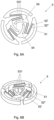
- FIG. 5A illustrates a top view of a clutch disc 5 of a clutch mechanism 100 according to another embodiment of the invention, in the engaged position.
- Figure 5B illustrates a perspective view of the clutch disc 5 of the Figure 5A .
- the central hub 53 comprises central flexible blades 530.
- they are three in number and define a substantially triangular opening; it should however be understood that this embodiment is not limited to such a number or to such a shape, provided that the shape created by the central flexible blades 530 is adapted to receive the shaft 3.
- these central flexible blades 530 form a friction system in the center of the disc.
- the level of penetration on the diameter of the shaft 3 and/or the flexibility of the three central blades 530 make it possible to adjust precisely the value of the torque for which shaft 3 slips when resetting.
- each central blade 530 is connected to at least one flexible blade 52 (or to a pair of parallel flexible blades in the illustrated embodiment) via an internal rigid clutch element 54 of the central hub 53.
- the flexible blade(s) 52 is (are) also connected to the corresponding peripheral rigid clutch element 51.
- the central hub 53 is arranged so as to limit the deformation of the central blades 530, in particular when the clamp 1 is actuated.
- the central hub 53 and in particular the part of the central hub 53 which is close to the central blades 530, acts as a stop for the central blades 530.
- peripheral rigid clutch elements 51 is three, this number is not limiting and another number of peripheral rigid clutch elements 51 equal to or greater than two can be envisaged.
- FIG. 6A illustrates a top view of a clutch disc 5 of a clutch mechanism 100 according to another embodiment of the invention, in the engaged position.
- Figure 6B illustrates a perspective view of the clutch disc 5 of the Figure 6A .
- the clutch disc 5 in the disengaged position and upon resetting, has a smaller diameter than that of the engaged position, and the central hub 53 has a larger diameter than that of the engaged position.
- the peripheral rigid clutch elements 51 move radially toward the center C of the clutch disc 5 and thus toward the shaft 3, while its central hub 53 moves away from the shaft 3. This also allows the friction torque for resetting to be precisely adjusted.
- the central hub 53 comprises at least two central rigid elements 531 defining the first diameter of the central hub 53 in the engaged position, and the second diameter in the disengaged position.
- the central rigid elements 531 come together in the engaged position (visible in the Figures 6A and 6B ), and move away in the disengaged position and when resetting the chronograph wheel (not shown).
- the central hub 53 comprises central rigid elements 531.
- they are three in number and define a substantially circular opening (they have a slightly curved shape), however this embodiment is not limited to such a number or to such a shape, provided that the shape created by the central rigid elements 530 is suitable for receiving the shaft 3.
- each central rigid element 531 is connected via an internal rigid clutch element 54 to two pairs of parallel flexible blades 52', 52": a first pair connects the internal rigid clutch element 54 to an adjacent internal rigid clutch element 54, and a second pair 52" connects the internal rigid clutch element 54 to a peripheral rigid clutch element 51.
- Each pair of parallel blades 52', 52" of the Figures 6A and 6B can be replaced with a single flexible blade.
- peripheral rigid clutch elements 51 is three, this number is not limiting and another number of peripheral rigid clutch elements equal to or greater than two can be envisaged.
- the overall torque of the clutch disc 5, including the torque related to friction with the first wheel 4 and the torque related to the deformation of the flexible blades 52, is in the range of 0.04 N mm to 0.09 N mm.
- FIG. 7 illustrates a top view of a clamp 1 of a clutch mechanism 100 according to another embodiment of the invention.
- the rigid body 13 moves in translation in a first direction R in a plane of the clamp 1, causing a translational movement of the jaws in a second direction M1, M2 (M1 having a direction opposite to M2) in this plane, the second direction M1, M2 being substantially perpendicular to the first direction R, the two jaws 10 moving closer (in the disengaged position) and moving away respectively (in the engaged position) during their movement.
- the clamp 1 may also comprise an external frame 14 which does not move when changing from the engaged position to the disengaged position.
- the frame 14 has a U shape and defines a space receiving the jaws 10 and the rigid body 13.
- the frame 14 comprises holes 140 of different dimensions, which allow it to be fixed in a movement. However, the presence of these holes 140 is not necessary and any other means of fixing the clamp 1 to the movement can be used by those skilled in the art.
- the two jaws 10 in the disengaged position therefore close concentrically on the clutch disc 5 (not shown). These jaws move in translation along a substantially rectilinear path. In one embodiment, this movement is obtained by means of two jaw movement mechanisms 120 arranged between the frame 14 and the jaws 10.
- each jaw movement mechanism 120 comprises a rigid element 17 arranged between two flexible blades 12.
- the mechanism for moving the jaws 120, and in particular the flexible blade(s) 12, deform(s) when moving from the engaged position to the disengaged position and vice versa, allowing the jaws 10 to be guided almost linearly.
- the rocker 19 is pushed in correspondence of its head 190 by a control device, for example a column wheel 9, in the direction of the arrow B of the Figure 7
- the first flexible blade 18 allows a pivot to be made and acts as a lever, allowing a change of direction at the other end of the rocker 9 (arrow C of the Figure 7 ).
- the flexible blade 17 makes it possible to compensate for the effect of the rotation of the rocker 19.
- the flexible blades 16 make it possible to obtain a trajectory inversion, that is to say they make it possible to transform the movement of the rigid body 13 in the direction R into a movement of the jaws 10 in the direction M1, M2.
- the jaw movement mechanisms 120 allow quasi-linear guidance of the jaws 10.
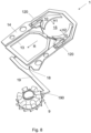
- FIG. 8 illustrates a perspective view of the clamp 1 of the Figure 7 , cooperating with a control device, for example a column wheel 9.
- the head 190 of the rocker 19 is at the bottom of a column of the column wheel 9.
- the clamp 1 is therefore not controlled and it is open (engaged position).
- clamps 1 are illustrated in the figures 9 to 11 .
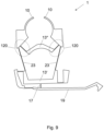
- FIG. 9 illustrates a top view of a clamp 1 of a clutch mechanism 100 according to another embodiment of the invention.
- the clamp 1 comprises a first rigid body 13' in the shape of a U and connected to the rocker 19 via the flexible blade 17, and a second rigid body 13" opposite the first 13' and in the shape of a C.
- the mechanisms for moving the jaws 120 comprise in this case two flexible blades, which are not necessarily parallel, one flexible blade connecting the first rigid body 13' to a jaw 10 and the other flexible blade connecting the second rigid body 13" to this jaw 10.
- the frame includes the 13" part and the two flexible blades 23 located on either side of the 13' part.
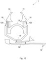
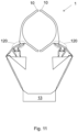
- FIG. 10 illustrates a top view of a clamp 1 of a clutch mechanism 100 according to another embodiment of the invention.
- the clamp 1 comprises a first rigid body 13' in the shape of a U and connected to the rocker 19 via the flexible blade 17, and a second rigid body 13" opposite the first 13' and in the shape of a C.
- a flexible blade 16 connects each of the jaws 10 to the first rigid body 13', a pair of parallel flexible blades 120 connecting each of the jaws 10 to the second rigid body 13".
- the rocker 19' cooperates with the first rigid body 13' via a second rocker 19".
- FIG. 11 illustrates a top view of a clamp 1 of a clutch mechanism 100 according to another embodiment of the invention.
- the jaw displacement mechanism 120 connecting each jaw 10 to the rigid body 13 comprises a specific arrangement of rigid bodies and flexible blades, allowing the transformation of the translational displacement of the rigid body 13 in a first direction in the plane of the clamp 1, into a translational displacement of the jaws in a second direction in this plane, the second direction being substantially perpendicular to the first direction.
- the flexible blades and/or the rigid bodies of the clutch disc 5 or the clamp 1 belong to the same plane, which is that of a planar plate.
- the plate can be produced by photolithography from a wafer, for example a silicon wafer, by laser cutting, by LIGA, etc.
- the clutch disc 5 or the clamp 1 is made of a composite material comprising a forest of juxtaposed nanotubes held by a matrix.
- the nanotubes are carbon nanotubes.
- the matrix comprises amorphous carbon.
- the nanotubes are made of other materials, for example boron nitride (“boron nitride nanotubes”, BNNT) or silicon.
- the clutch disc 5 or the clamp 1 is made of steel.
- the clutch disc 5 or the clamp 1 is made of glass, sapphire or alumina, of diamond, in particular synthetic diamond (in particular synthetic diamond obtained by a chemical vapor deposition process), of titanium, of titanium alloy (in particular an alloy of the Gum metal (R) family) or an alloy of the elinvar family, in particular Elinvar (R), Nivarox (R), Thermelast (R), NI-Span-C (R) and Precision C (R), of shape memory alloy, in particular Nitinol, of plastic or of any other material having a Young's modulus which is very insensitive to temperature variations.
- diamond in particular synthetic diamond (in particular synthetic diamond obtained by a chemical vapor deposition process)
- titanium of titanium alloy (in particular an alloy of the Gum metal (R) family) or an alloy of the elinvar family, in particular Elinvar (R), Nivarox (R), Thermelast (R), NI-Span-C (R) and Precision C
Landscapes
- Physics & Mathematics (AREA)
- General Physics & Mathematics (AREA)
- Mechanical Operated Clutches (AREA)
- Electromechanical Clocks (AREA)
Claims (15)
- Kupplungs-Uhrmechanismus (100), umfassend:- eine Welle (3),- ein erstes Rad (4), welches derart angeordnet ist, um frei drehbar auf der Welle (3) gelagert zu sein und sich kontinuierlich um die Welle (3) zu drehen,- eine an der Welle (3) fest verbundene Kupplungsscheibe (5),- eine Steuereinrichtung (9),worin der Mechanismus (100) derart angeordnet ist, um unter der Einwirkung der Steuervorrichtung (9) von einer eingekuppelten Stellung in eine ausgekuppelte Stellung und umgekehrt zu gelangen,worindie Kupplungsscheibe (5) zu einer Ebene senkrecht zur Welle (3) gehört und in dieser Ebene umfasst:- eine mit der Welle (3) zusammenwirkende Zentralnabe (53),dadurch gekennzeichnet, dass der Kupplungs-Uhrmechanismus (100) umfasst:- ein zweites Rad (2), welches an der Welle (3) fest verbunden ist, und dass die Kupplungsscheibe (5) in einer Ebene senkrecht zur Welle (3) umfasst:- mindestens zwei periphere starre Kupplungselemente (51), und- mindestens eine flexible Klinge (52), welche jedes periphere starre Kupplungselement (51) mit der Zentralnabe (53) verbindet,und worindie flexiblen Klingen (52) derart angeordnet sind, um sich in dieser Ebene zu verformen, so dass- in der eingekuppelten Stellung die Kupplungsscheibe (5) einen ersten Durchmesser (D1) aufweist, so dass die peripheren starren Kupplungselemente (51) mit einer Oberfläche (42) des ersten Rades (4) in Kontakt kommen, wobei das erste Rad (4) durch diesen Kontakt die Kupplungsscheibe (5) antreibt, so dass die Kupplungsscheibe (5) somit die Welle (3) antreibt und die Welle (3) das zweite Rad (2) antreibt,- in der ausgekuppelten Stellung die Kupplungsscheibe (5) einen zweiten Durchmesser (D2) aufweist, welcher kleiner als der erste Durchmesser (D1) ist, so dass die peripheren starren Kupplungselemente (51) nicht mehr mit der Oberfläche (42) des ersten Rades (4) in Kontakt kommen.
- Mechanismus (100) gemäss Anspruch 1, worin die peripheren starren Kupplungselemente (51) derart angeordnet sind, um sich unter der Einwirkung der flexiblen Klingen (52) mit einer im Wesentlichen translatorischen Bewegung in einer radialen Richtung der Kupplungsscheibe (5) zu bewegen.
- Mechanismus (100) gemäss einem der Ansprüche 1 oder 2, worin das erste Rad (4) ein Gehäuse (40) umfasst, welches derart angeordnet ist, um die Kupplungsscheibe (5) zumindest teilweise in Richtung (A) der Welle (3) aufzunehmen.
- Mechanismus (100) gemäss einem der Ansprüche 1 bis 3, worin in der eingekuppelten Stellung jede flexible Klinge (42) im Wesentlichen gerade ist.
- Mechanismus (100) gemäss einem der Ansprüche 1 bis 4, worin die peripheren starren Kupplungselemente (51) kreisbogenförmig ausgebildet sind und/oder einen kreisbogenförmigen Abschnitt umfassen.
- Mechanismus (100) gemäss einem der Ansprüche 1 bis 5, worin mindestens ein peripheres starres Kupplungselement (51) durch ein Paar paralleler flexibler Klingen (52) mit der Zentralnabe (53) verbunden ist.
- Mechanismus (100) gemäss einem der Ansprüche 1 bis 6, wobei das zweite Rad (2) ein Chronographenrad ist, wobei die Zentralnabe (53) zentrale flexible Klingen (530) umfasst.
- Mechanismus (100) gemäss Anspruch 7, wobei die Zentralnabe (53) derart angeordnet ist, um die Verformung der zentralen flexiblen Klingen (530) zu begrenzen.
- Mechanismus (100) gemäss einem der Ansprüche 1 bis 6, wobei das zweite Rad (2) ein Chronographenrad ist, wobei die Zentralnabe (53) derart angeordnet ist, dass- in der eingekuppelten Stellung die Zentralnabe (53) einen ersten Durchmesser aufweist, um mit der Welle (3) in Kontakt zu kommen,- in der ausgekuppelten Stellung und beim Rückstellen des Chronographenrades durch einen Rückstellmechanismus die Zentralnabe (3) einen zweiten Durchmesser aufweist, welcher grösser als der erste Durchmesser ist, so dass die Welle (3) auf der Zentralnabe (53) gleiten kann.
- Mechanismus gemäss Anspruch 9, wobei die Zentralnabe (3) mindestens zwei zentrale starre Elemente (531) umfasst, welche den ersten Durchmesser in der eingekuppelten Stellung und den zweiten Durchmesser in der ausgekuppelten Stellung und beim Zurücksetzen des Chronographenrades definieren.
- Mechanismus (100) gemäss einem der Ansprüche 1 bis 10, worin mindestens ein peripheres starres Kupplungselement (51) eine erste Fläche (F) und eine zweite Fläche (P) umfasst, welche in Richtung (A) der Welle (3) an die erste Fläche (F) angrenzt, so dass:- in der eingekuppelten Stellung die erste Fläche (F) in Kontakt mit dem ersten Rad (4) steht, wobei die zweite Fläche (P) von einer Klammer (1) weg bewegt ist;- in der ausgekuppelten Stellung die Klammer (1) mit der zweiten Fläche (P) in Kontakt kommt, wodurch die erste Fläche (F) vom ersten Rad (4) wegbewegt wird.
- Mechanismus (100) gemäss Anspruch 11, wobei die Klammer (1) umfasst:- einen starren Körper (13),- zwei Backen (10), welche derart angeordnet sind, um mit der Kupplungsscheibe (5) zusammenzuwirken,- flexible Klingen (12, 16), welche den starren Körper (13) mit den Backen (10) verbinden, worin sich der starre Körper (13) beim Wechsel von der eingekuppelten Stellung in die ausgekuppelte Stellung translatorisch in einer ersten Richtung (R) in einer Ebene der Klemme bewegt, was eine translatorische Bewegung der Backen (10) in einer zweiten Richtung (M1, M2) in dieser Ebene bewirkt, wobei die zweite Richtung (M1, M2) im Wesentlichen senkrecht zur ersten Richtung (R) verläuft, und sich die beiden Backen (10) während ihrer Bewegung jeweils näher zusammenkommen bzw. voneinander entfernen.
- Mechanismus (100) gemäss einem der Ansprüche 11 oder 12, wobei die Klammer (1) einen Rahmen (14) umfasst, welcher sich beim Wechsel von der eingekuppelten Stellung in die ausgekuppelte Stellung nicht bewegt.
- Mechanismus (100) gemäss Anspruch 13, wobei die Klammer (1) eine Wippe (19) umfasst, welche derart angeordnet ist, um mit der Steuervorrichtung (9) zusammenzuwirken, und eine erste flexible Klinge (17), welche die Wippe (19) mit dem Rahmen (14) verbindet, und eine zweite flexible Klinge (18), welche die Wippe (19) mit dem starren Körper (13) verbindet.
- Mechanismus (100) gemäss einem der Ansprüche 13 oder 14, wobei der Rahmen (14) mit jeder Backe über einen Backenbewegungsmechanismus (120) verbunden ist, welcher umfasst:- mindestens eine flexible Klinge (12),- mindestens ein starres Element (17) seriell mit der flexiblen Klinge (12).
Applications Claiming Priority (1)
| Application Number | Priority Date | Filing Date | Title |
|---|---|---|---|
| CH070378/2021A CH719048A9 (fr) | 2021-10-11 | 2021-10-11 | Mécanisme horloger d'embrayage. |
Publications (2)
| Publication Number | Publication Date |
|---|---|
| EP4163732A1 EP4163732A1 (de) | 2023-04-12 |
| EP4163732B1 true EP4163732B1 (de) | 2025-06-18 |
Family
ID=85463128
Family Applications (1)
| Application Number | Title | Priority Date | Filing Date |
|---|---|---|---|
| EP22199695.2A Active EP4163732B1 (de) | 2021-10-11 | 2022-10-05 | Kupplungsuhrmechanismus |
Country Status (2)
| Country | Link |
|---|---|
| EP (1) | EP4163732B1 (de) |
| CH (1) | CH719048A9 (de) |
Family Cites Families (3)
| Publication number | Priority date | Publication date | Assignee | Title |
|---|---|---|---|---|
| EP2085832B1 (de) | 2008-02-04 | 2013-04-10 | Blancpain SA. | Chronographenvorrichtung mit Reibungskupplung |
| CH709153A1 (fr) * | 2014-01-16 | 2015-07-31 | Richemont Int Sa | Mécanisme rattrapante à isolation et pièce d'horlogerie mécanique comportant un mécanisme de chronographe muni de ce mécanisme rattrapante à isolation. |
| EP3671370B1 (de) | 2018-12-20 | 2021-08-04 | Patek Philippe SA Genève | Kupplungsvorrichtung und chronographenmechanismus, der eine solche kupplungsvorrichtung umfasst |
-
2021
- 2021-10-11 CH CH070378/2021A patent/CH719048A9/fr unknown
-
2022
- 2022-10-05 EP EP22199695.2A patent/EP4163732B1/de active Active
Also Published As
| Publication number | Publication date |
|---|---|
| EP4163732A1 (de) | 2023-04-12 |
| CH719048A9 (fr) | 2023-06-30 |
| CH719048A1 (fr) | 2023-04-14 |
Similar Documents
| Publication | Publication Date | Title |
|---|---|---|
| CH712219A2 (fr) | Mécanisme pour mouvement de montre à affichage rétrograde et sautant. | |
| EP2957964B1 (de) | Kippkupplung für uhren | |
| EP3671370B1 (de) | Kupplungsvorrichtung und chronographenmechanismus, der eine solche kupplungsvorrichtung umfasst | |
| CH710108A2 (fr) | Mécanisme à force constante, mouvement et pièce d'horlogerie. | |
| CH710118B1 (fr) | Pièce d'engrenage, mécanisme de réglage d'une différence horaire, mouvement horloger, et pièce d'horlogerie. | |
| EP4163732B1 (de) | Kupplungsuhrmechanismus | |
| EP3196710B1 (de) | Uhrwerk, das eine analoganzeige umfasst | |
| EP3598243B1 (de) | Uhrmechanismus mit organ, das sich in sprüngen bewegt | |
| EP2096504A2 (de) | Mechanismus zur Anzeige der toten Sekunden | |
| EP1960843B1 (de) | Uhrwerk | |
| EP2249215B1 (de) | Chronographuhr mit sofortiger anzeige von sekunden-bruchteilen | |
| EP4425272B1 (de) | Uhrmechanismus | |
| EP4425275B1 (de) | Uhrmechanismus | |
| CH715546B1 (fr) | Mécanisme d'affichage pour mouvement horloger. | |
| WO2025037233A1 (fr) | Mécanisme horloger pour chronographe à rattrapante | |
| EP4544361A1 (de) | Bistabiler uhrsteuermechanismus | |
| CH719810A2 (fr) | Mécanisme horloger, notamment pour une montre-chronographe | |
| CH719809A2 (fr) | Mécanisme horloger, notamment pour une montre-chronographe | |
| EP4544360A1 (de) | Bistabiler uhrsteuermechanismus | |
| EP1960846A2 (de) | Uhrwerk | |
| EP4425274A1 (de) | Uhrmechanismus | |
| CH720566A2 (fr) | Mécanisme horloger pour entraîner une roue avec des sauts | |
| CH715924B1 (fr) | Dispositif d'embrayage latéral pour chronographe avec excentrique d'alignement de dents et mouvement de montre chronographe comprenant un tel dispositif. | |
| CH720568A2 (fr) | Mécanisme horloger anti-double saut d'une roue d'affichage à saut instantané | |
| CH720565A2 (fr) | Mécanisme horloger |
Legal Events
| Date | Code | Title | Description |
|---|---|---|---|
| PUAI | Public reference made under article 153(3) epc to a published international application that has entered the european phase |
Free format text: ORIGINAL CODE: 0009012 |
|
| STAA | Information on the status of an ep patent application or granted ep patent |
Free format text: STATUS: THE APPLICATION HAS BEEN PUBLISHED |
|
| AK | Designated contracting states |
Kind code of ref document: A1 Designated state(s): AL AT BE BG CH CY CZ DE DK EE ES FI FR GB GR HR HU IE IS IT LI LT LU LV MC ME MK MT NL NO PL PT RO RS SE SI SK SM TR |
|
| STAA | Information on the status of an ep patent application or granted ep patent |
Free format text: STATUS: REQUEST FOR EXAMINATION WAS MADE |
|
| 17P | Request for examination filed |
Effective date: 20231019 |
|
| RBV | Designated contracting states (corrected) |
Designated state(s): AL AT BE BG CH CY CZ DE DK EE ES FI FR GB GR HR HU IE IS IT LI LT LU LV MC ME MK MT NL NO PL PT RO RS SE SI SK SM TR |
|
| GRAP | Despatch of communication of intention to grant a patent |
Free format text: ORIGINAL CODE: EPIDOSNIGR1 |
|
| STAA | Information on the status of an ep patent application or granted ep patent |
Free format text: STATUS: GRANT OF PATENT IS INTENDED |
|
| RIC1 | Information provided on ipc code assigned before grant |
Ipc: G04F 7/08 20060101ALI20241219BHEP Ipc: G04B 11/00 20060101AFI20241219BHEP |
|
| INTG | Intention to grant announced |
Effective date: 20250121 |
|
| GRAS | Grant fee paid |
Free format text: ORIGINAL CODE: EPIDOSNIGR3 |
|
| GRAA | (expected) grant |
Free format text: ORIGINAL CODE: 0009210 |
|
| STAA | Information on the status of an ep patent application or granted ep patent |
Free format text: STATUS: THE PATENT HAS BEEN GRANTED |
|
| AK | Designated contracting states |
Kind code of ref document: B1 Designated state(s): AL AT BE BG CH CY CZ DE DK EE ES FI FR GB GR HR HU IE IS IT LI LT LU LV MC ME MK MT NL NO PL PT RO RS SE SI SK SM TR |
|
| REG | Reference to a national code |
Ref country code: GB Ref legal event code: FG4D Free format text: NOT ENGLISH |
|
| REG | Reference to a national code |
Ref country code: CH Ref legal event code: EP |
|
| REG | Reference to a national code |
Ref country code: DE Ref legal event code: R096 Ref document number: 602022016024 Country of ref document: DE |
|
| REG | Reference to a national code |
Ref country code: CH Ref legal event code: EP |
|
| REG | Reference to a national code |
Ref country code: IE Ref legal event code: FG4D Free format text: LANGUAGE OF EP DOCUMENT: FRENCH |
|
| REG | Reference to a national code |
Ref country code: NL Ref legal event code: FP |
|
| PG25 | Lapsed in a contracting state [announced via postgrant information from national office to epo] |
Ref country code: FI Free format text: LAPSE BECAUSE OF FAILURE TO SUBMIT A TRANSLATION OF THE DESCRIPTION OR TO PAY THE FEE WITHIN THE PRESCRIBED TIME-LIMIT Effective date: 20250618 |
|
| REG | Reference to a national code |
Ref country code: LT Ref legal event code: MG9D |
|
| PG25 | Lapsed in a contracting state [announced via postgrant information from national office to epo] |
Ref country code: NO Free format text: LAPSE BECAUSE OF FAILURE TO SUBMIT A TRANSLATION OF THE DESCRIPTION OR TO PAY THE FEE WITHIN THE PRESCRIBED TIME-LIMIT Effective date: 20250918 Ref country code: GR Free format text: LAPSE BECAUSE OF FAILURE TO SUBMIT A TRANSLATION OF THE DESCRIPTION OR TO PAY THE FEE WITHIN THE PRESCRIBED TIME-LIMIT Effective date: 20250919 |
|
| PGFP | Annual fee paid to national office [announced via postgrant information from national office to epo] |
Ref country code: NL Payment date: 20250923 Year of fee payment: 4 |
|
| PG25 | Lapsed in a contracting state [announced via postgrant information from national office to epo] |
Ref country code: BG Free format text: LAPSE BECAUSE OF FAILURE TO SUBMIT A TRANSLATION OF THE DESCRIPTION OR TO PAY THE FEE WITHIN THE PRESCRIBED TIME-LIMIT Effective date: 20250618 |
|
| PG25 | Lapsed in a contracting state [announced via postgrant information from national office to epo] |
Ref country code: HR Free format text: LAPSE BECAUSE OF FAILURE TO SUBMIT A TRANSLATION OF THE DESCRIPTION OR TO PAY THE FEE WITHIN THE PRESCRIBED TIME-LIMIT Effective date: 20250618 |
|
| PGFP | Annual fee paid to national office [announced via postgrant information from national office to epo] |
Ref country code: FR Payment date: 20250924 Year of fee payment: 4 |
|
| PG25 | Lapsed in a contracting state [announced via postgrant information from national office to epo] |
Ref country code: RS Free format text: LAPSE BECAUSE OF FAILURE TO SUBMIT A TRANSLATION OF THE DESCRIPTION OR TO PAY THE FEE WITHIN THE PRESCRIBED TIME-LIMIT Effective date: 20250918 |
|
| PG25 | Lapsed in a contracting state [announced via postgrant information from national office to epo] |
Ref country code: LV Free format text: LAPSE BECAUSE OF FAILURE TO SUBMIT A TRANSLATION OF THE DESCRIPTION OR TO PAY THE FEE WITHIN THE PRESCRIBED TIME-LIMIT Effective date: 20250618 |
|
| REG | Reference to a national code |
Ref country code: CH Ref legal event code: U11 Free format text: ST27 STATUS EVENT CODE: U-0-0-U10-U11 (AS PROVIDED BY THE NATIONAL OFFICE) Effective date: 20251101 |
|
| PG25 | Lapsed in a contracting state [announced via postgrant information from national office to epo] |
Ref country code: PT Free format text: LAPSE BECAUSE OF FAILURE TO SUBMIT A TRANSLATION OF THE DESCRIPTION OR TO PAY THE FEE WITHIN THE PRESCRIBED TIME-LIMIT Effective date: 20251020 |
|
| REG | Reference to a national code |
Ref country code: AT Ref legal event code: MK05 Ref document number: 1804752 Country of ref document: AT Kind code of ref document: T Effective date: 20250618 |
|
| PG25 | Lapsed in a contracting state [announced via postgrant information from national office to epo] |
Ref country code: IS Free format text: LAPSE BECAUSE OF FAILURE TO SUBMIT A TRANSLATION OF THE DESCRIPTION OR TO PAY THE FEE WITHIN THE PRESCRIBED TIME-LIMIT Effective date: 20251018 |
|
| PGFP | Annual fee paid to national office [announced via postgrant information from national office to epo] |
Ref country code: DE Payment date: 20250923 Year of fee payment: 4 |
|
| PG25 | Lapsed in a contracting state [announced via postgrant information from national office to epo] |
Ref country code: AT Free format text: LAPSE BECAUSE OF FAILURE TO SUBMIT A TRANSLATION OF THE DESCRIPTION OR TO PAY THE FEE WITHIN THE PRESCRIBED TIME-LIMIT Effective date: 20250618 Ref country code: SM Free format text: LAPSE BECAUSE OF FAILURE TO SUBMIT A TRANSLATION OF THE DESCRIPTION OR TO PAY THE FEE WITHIN THE PRESCRIBED TIME-LIMIT Effective date: 20250618 |
|
| PGFP | Annual fee paid to national office [announced via postgrant information from national office to epo] |
Ref country code: CH Payment date: 20251101 Year of fee payment: 4 |
|
| PG25 | Lapsed in a contracting state [announced via postgrant information from national office to epo] |
Ref country code: CZ Free format text: LAPSE BECAUSE OF FAILURE TO SUBMIT A TRANSLATION OF THE DESCRIPTION OR TO PAY THE FEE WITHIN THE PRESCRIBED TIME-LIMIT Effective date: 20250618 |
|
| PG25 | Lapsed in a contracting state [announced via postgrant information from national office to epo] |
Ref country code: PL Free format text: LAPSE BECAUSE OF FAILURE TO SUBMIT A TRANSLATION OF THE DESCRIPTION OR TO PAY THE FEE WITHIN THE PRESCRIBED TIME-LIMIT Effective date: 20250618 |
|
| PG25 | Lapsed in a contracting state [announced via postgrant information from national office to epo] |
Ref country code: EE Free format text: LAPSE BECAUSE OF FAILURE TO SUBMIT A TRANSLATION OF THE DESCRIPTION OR TO PAY THE FEE WITHIN THE PRESCRIBED TIME-LIMIT Effective date: 20250618 |
|
| PG25 | Lapsed in a contracting state [announced via postgrant information from national office to epo] |
Ref country code: SK Free format text: LAPSE BECAUSE OF FAILURE TO SUBMIT A TRANSLATION OF THE DESCRIPTION OR TO PAY THE FEE WITHIN THE PRESCRIBED TIME-LIMIT Effective date: 20250618 |
|
| PG25 | Lapsed in a contracting state [announced via postgrant information from national office to epo] |
Ref country code: ES Free format text: LAPSE BECAUSE OF FAILURE TO SUBMIT A TRANSLATION OF THE DESCRIPTION OR TO PAY THE FEE WITHIN THE PRESCRIBED TIME-LIMIT Effective date: 20250618 |
|
| PG25 | Lapsed in a contracting state [announced via postgrant information from national office to epo] |
Ref country code: RO Free format text: LAPSE BECAUSE OF FAILURE TO SUBMIT A TRANSLATION OF THE DESCRIPTION OR TO PAY THE FEE WITHIN THE PRESCRIBED TIME-LIMIT Effective date: 20250618 |
|
| PG25 | Lapsed in a contracting state [announced via postgrant information from national office to epo] |
Ref country code: DK Free format text: LAPSE BECAUSE OF FAILURE TO SUBMIT A TRANSLATION OF THE DESCRIPTION OR TO PAY THE FEE WITHIN THE PRESCRIBED TIME-LIMIT Effective date: 20250618 |
|
| PG25 | Lapsed in a contracting state [announced via postgrant information from national office to epo] |
Ref country code: IT Free format text: LAPSE BECAUSE OF FAILURE TO SUBMIT A TRANSLATION OF THE DESCRIPTION OR TO PAY THE FEE WITHIN THE PRESCRIBED TIME-LIMIT Effective date: 20250618 |
|
| PLBE | No opposition filed within time limit |
Free format text: ORIGINAL CODE: 0009261 |
|
| STAA | Information on the status of an ep patent application or granted ep patent |
Free format text: STATUS: NO OPPOSITION FILED WITHIN TIME LIMIT |
|
| REG | Reference to a national code |
Ref country code: CH Ref legal event code: L10 Free format text: ST27 STATUS EVENT CODE: U-0-0-L10-L00 (AS PROVIDED BY THE NATIONAL OFFICE) Effective date: 20260430 |