EP4164015A1 - Materialzufuhrvorrichtung für sekundärbatterieseparator - Google Patents
Materialzufuhrvorrichtung für sekundärbatterieseparator Download PDFInfo
- Publication number
- EP4164015A1 EP4164015A1 EP22788492.1A EP22788492A EP4164015A1 EP 4164015 A1 EP4164015 A1 EP 4164015A1 EP 22788492 A EP22788492 A EP 22788492A EP 4164015 A1 EP4164015 A1 EP 4164015A1
- Authority
- EP
- European Patent Office
- Prior art keywords
- raw material
- separator
- supplied
- supply device
- conveying cylinder
- Prior art date
- Legal status (The legal status is an assumption and is not a legal conclusion. Google has not performed a legal analysis and makes no representation as to the accuracy of the status listed.)
- Granted
Links
Images




Classifications
-
- H—ELECTRICITY
- H01—ELECTRIC ELEMENTS
- H01M—PROCESSES OR MEANS, e.g. BATTERIES, FOR THE DIRECT CONVERSION OF CHEMICAL ENERGY INTO ELECTRICAL ENERGY
- H01M50/00—Constructional details or processes of manufacture of the non-active parts of electrochemical cells other than fuel cells, e.g. hybrid cells
- H01M50/40—Separators; Membranes; Diaphragms; Spacing elements inside cells
- H01M50/403—Manufacturing processes of separators, membranes or diaphragms
-
- B—PERFORMING OPERATIONS; TRANSPORTING
- B65—CONVEYING; PACKING; STORING; HANDLING THIN OR FILAMENTARY MATERIAL
- B65H—HANDLING THIN OR FILAMENTARY MATERIAL, e.g. SHEETS, WEBS, CABLES
- B65H19/00—Changing the web roll
- B65H19/10—Changing the web roll in unwinding mechanisms or in connection with unwinding operations
- B65H19/18—Attaching, e.g. pasting, the replacement web to the expiring web
-
- B—PERFORMING OPERATIONS; TRANSPORTING
- B65—CONVEYING; PACKING; STORING; HANDLING THIN OR FILAMENTARY MATERIAL
- B65H—HANDLING THIN OR FILAMENTARY MATERIAL, e.g. SHEETS, WEBS, CABLES
- B65H19/00—Changing the web roll
- B65H19/10—Changing the web roll in unwinding mechanisms or in connection with unwinding operations
- B65H19/18—Attaching, e.g. pasting, the replacement web to the expiring web
- B65H19/1842—Attaching, e.g. pasting, the replacement web to the expiring web standing splicing, i.e. the expiring web being stationary during splicing contact
- B65H19/1852—Attaching, e.g. pasting, the replacement web to the expiring web standing splicing, i.e. the expiring web being stationary during splicing contact taking place at a distance from the replacement roll
-
- B—PERFORMING OPERATIONS; TRANSPORTING
- B65—CONVEYING; PACKING; STORING; HANDLING THIN OR FILAMENTARY MATERIAL
- B65H—HANDLING THIN OR FILAMENTARY MATERIAL, e.g. SHEETS, WEBS, CABLES
- B65H20/00—Advancing webs
- B65H20/16—Advancing webs by web-gripping means, e.g. grippers, clips
-
- B—PERFORMING OPERATIONS; TRANSPORTING
- B65—CONVEYING; PACKING; STORING; HANDLING THIN OR FILAMENTARY MATERIAL
- B65H—HANDLING THIN OR FILAMENTARY MATERIAL, e.g. SHEETS, WEBS, CABLES
- B65H21/00—Apparatus for splicing webs
-
- B—PERFORMING OPERATIONS; TRANSPORTING
- B65—CONVEYING; PACKING; STORING; HANDLING THIN OR FILAMENTARY MATERIAL
- B65H—HANDLING THIN OR FILAMENTARY MATERIAL, e.g. SHEETS, WEBS, CABLES
- B65H23/00—Registering, tensioning, smoothing or guiding webs
- B65H23/04—Registering, tensioning, smoothing or guiding webs longitudinally
- B65H23/26—Registering, tensioning, smoothing or guiding webs longitudinally by transverse stationary or adjustable bars or rollers
-
- H—ELECTRICITY
- H01—ELECTRIC ELEMENTS
- H01M—PROCESSES OR MEANS, e.g. BATTERIES, FOR THE DIRECT CONVERSION OF CHEMICAL ENERGY INTO ELECTRICAL ENERGY
- H01M10/00—Secondary cells; Manufacture thereof
- H01M10/04—Construction or manufacture in general
-
- H—ELECTRICITY
- H01—ELECTRIC ELEMENTS
- H01M—PROCESSES OR MEANS, e.g. BATTERIES, FOR THE DIRECT CONVERSION OF CHEMICAL ENERGY INTO ELECTRICAL ENERGY
- H01M10/00—Secondary cells; Manufacture thereof
- H01M10/04—Construction or manufacture in general
- H01M10/0404—Machines for assembling batteries
-
- H—ELECTRICITY
- H01—ELECTRIC ELEMENTS
- H01M—PROCESSES OR MEANS, e.g. BATTERIES, FOR THE DIRECT CONVERSION OF CHEMICAL ENERGY INTO ELECTRICAL ENERGY
- H01M10/00—Secondary cells; Manufacture thereof
- H01M10/04—Construction or manufacture in general
- H01M10/0404—Machines for assembling batteries
- H01M10/0409—Machines for assembling batteries for cells with wound electrodes
-
- H—ELECTRICITY
- H01—ELECTRIC ELEMENTS
- H01M—PROCESSES OR MEANS, e.g. BATTERIES, FOR THE DIRECT CONVERSION OF CHEMICAL ENERGY INTO ELECTRICAL ENERGY
- H01M50/00—Constructional details or processes of manufacture of the non-active parts of electrochemical cells other than fuel cells, e.g. hybrid cells
- H01M50/40—Separators; Membranes; Diaphragms; Spacing elements inside cells
- H01M50/403—Manufacturing processes of separators, membranes or diaphragms
- H01M50/406—Moulding; Embossing; Cutting
-
- H—ELECTRICITY
- H01—ELECTRIC ELEMENTS
- H01M—PROCESSES OR MEANS, e.g. BATTERIES, FOR THE DIRECT CONVERSION OF CHEMICAL ENERGY INTO ELECTRICAL ENERGY
- H01M50/00—Constructional details or processes of manufacture of the non-active parts of electrochemical cells other than fuel cells, e.g. hybrid cells
- H01M50/40—Separators; Membranes; Diaphragms; Spacing elements inside cells
- H01M50/409—Separators, membranes or diaphragms characterised by the material
- H01M50/411—Organic material
- H01M50/414—Synthetic resins, e.g. thermoplastics or thermosetting resins
- H01M50/417—Polyolefins
-
- H—ELECTRICITY
- H01—ELECTRIC ELEMENTS
- H01M—PROCESSES OR MEANS, e.g. BATTERIES, FOR THE DIRECT CONVERSION OF CHEMICAL ENERGY INTO ELECTRICAL ENERGY
- H01M50/00—Constructional details or processes of manufacture of the non-active parts of electrochemical cells other than fuel cells, e.g. hybrid cells
- H01M50/40—Separators; Membranes; Diaphragms; Spacing elements inside cells
- H01M50/409—Separators, membranes or diaphragms characterised by the material
- H01M50/449—Separators, membranes or diaphragms characterised by the material having a layered structure
-
- H—ELECTRICITY
- H01—ELECTRIC ELEMENTS
- H01M—PROCESSES OR MEANS, e.g. BATTERIES, FOR THE DIRECT CONVERSION OF CHEMICAL ENERGY INTO ELECTRICAL ENERGY
- H01M50/00—Constructional details or processes of manufacture of the non-active parts of electrochemical cells other than fuel cells, e.g. hybrid cells
- H01M50/40—Separators; Membranes; Diaphragms; Spacing elements inside cells
- H01M50/409—Separators, membranes or diaphragms characterised by the material
- H01M50/449—Separators, membranes or diaphragms characterised by the material having a layered structure
- H01M50/451—Separators, membranes or diaphragms characterised by the material having a layered structure comprising layers of only organic material and layers containing inorganic material
-
- H—ELECTRICITY
- H01—ELECTRIC ELEMENTS
- H01M—PROCESSES OR MEANS, e.g. BATTERIES, FOR THE DIRECT CONVERSION OF CHEMICAL ENERGY INTO ELECTRICAL ENERGY
- H01M50/00—Constructional details or processes of manufacture of the non-active parts of electrochemical cells other than fuel cells, e.g. hybrid cells
- H01M50/40—Separators; Membranes; Diaphragms; Spacing elements inside cells
- H01M50/46—Separators, membranes or diaphragms characterised by their combination with electrodes
-
- B—PERFORMING OPERATIONS; TRANSPORTING
- B23—MACHINE TOOLS; METAL-WORKING NOT OTHERWISE PROVIDED FOR
- B23K—SOLDERING OR UNSOLDERING; WELDING; CLADDING OR PLATING BY SOLDERING OR WELDING; CUTTING BY APPLYING HEAT LOCALLY, e.g. FLAME CUTTING; WORKING BY LASER BEAM
- B23K20/00—Non-electric welding by applying impact or other pressure, with or without the application of heat, e.g. cladding or plating
- B23K20/10—Non-electric welding by applying impact or other pressure, with or without the application of heat, e.g. cladding or plating making use of vibrations, e.g. ultrasonic welding
-
- B—PERFORMING OPERATIONS; TRANSPORTING
- B65—CONVEYING; PACKING; STORING; HANDLING THIN OR FILAMENTARY MATERIAL
- B65H—HANDLING THIN OR FILAMENTARY MATERIAL, e.g. SHEETS, WEBS, CABLES
- B65H2301/00—Handling processes for sheets or webs
- B65H2301/40—Type of handling process
- B65H2301/44—Moving, forwarding, guiding material
- B65H2301/443—Moving, forwarding, guiding material by acting on surface of handled material
- B65H2301/4433—Moving, forwarding, guiding material by acting on surface of handled material by means holding the material
- B65H2301/44336—Moving, forwarding, guiding material by acting on surface of handled material by means holding the material using suction forces
-
- B—PERFORMING OPERATIONS; TRANSPORTING
- B65—CONVEYING; PACKING; STORING; HANDLING THIN OR FILAMENTARY MATERIAL
- B65H—HANDLING THIN OR FILAMENTARY MATERIAL, e.g. SHEETS, WEBS, CABLES
- B65H2301/00—Handling processes for sheets or webs
- B65H2301/40—Type of handling process
- B65H2301/46—Splicing
- B65H2301/462—Form of splice
- B65H2301/4621—Overlapping article or web portions
-
- B—PERFORMING OPERATIONS; TRANSPORTING
- B65—CONVEYING; PACKING; STORING; HANDLING THIN OR FILAMENTARY MATERIAL
- B65H—HANDLING THIN OR FILAMENTARY MATERIAL, e.g. SHEETS, WEBS, CABLES
- B65H2301/00—Handling processes for sheets or webs
- B65H2301/40—Type of handling process
- B65H2301/46—Splicing
- B65H2301/463—Splicing splicing means, i.e. means by which a web end is bound to another web end
- B65H2301/46327—Ultrasonic sealing
-
- B—PERFORMING OPERATIONS; TRANSPORTING
- B65—CONVEYING; PACKING; STORING; HANDLING THIN OR FILAMENTARY MATERIAL
- B65H—HANDLING THIN OR FILAMENTARY MATERIAL, e.g. SHEETS, WEBS, CABLES
- B65H2406/00—Means using fluid
- B65H2406/30—Suction means
- B65H2406/34—Suction grippers
- B65H2406/342—Suction grippers being reciprocated in a rectilinear path
-
- B—PERFORMING OPERATIONS; TRANSPORTING
- B65—CONVEYING; PACKING; STORING; HANDLING THIN OR FILAMENTARY MATERIAL
- B65H—HANDLING THIN OR FILAMENTARY MATERIAL, e.g. SHEETS, WEBS, CABLES
- B65H2701/00—Handled material; Storage means
- B65H2701/10—Handled articles or webs
- B65H2701/19—Specific article or web
-
- B—PERFORMING OPERATIONS; TRANSPORTING
- B65—CONVEYING; PACKING; STORING; HANDLING THIN OR FILAMENTARY MATERIAL
- B65H—HANDLING THIN OR FILAMENTARY MATERIAL, e.g. SHEETS, WEBS, CABLES
- B65H2801/00—Application field
- B65H2801/72—Fuel cell manufacture
-
- Y—GENERAL TAGGING OF NEW TECHNOLOGICAL DEVELOPMENTS; GENERAL TAGGING OF CROSS-SECTIONAL TECHNOLOGIES SPANNING OVER SEVERAL SECTIONS OF THE IPC; TECHNICAL SUBJECTS COVERED BY FORMER USPC CROSS-REFERENCE ART COLLECTIONS [XRACs] AND DIGESTS
- Y02—TECHNOLOGIES OR APPLICATIONS FOR MITIGATION OR ADAPTATION AGAINST CLIMATE CHANGE
- Y02E—REDUCTION OF GREENHOUSE GAS [GHG] EMISSIONS, RELATED TO ENERGY GENERATION, TRANSMISSION OR DISTRIBUTION
- Y02E60/00—Enabling technologies; Technologies with a potential or indirect contribution to GHG emissions mitigation
- Y02E60/10—Energy storage using batteries
Definitions
- the present invention relates to a raw material supply device for a separator of a secondary battery. Specifically, the present invention relates to an apparatus capable of continuously supplying a raw material by automatically bonding the end portion of a raw material in use with the end portion of a new raw material, in connection with a roll type raw material for the separator of a secondary battery.
- a secondary battery is a chemical battery that can be used semi-permanently by continuously repeating charging and discharging using an electrochemical reaction, which is classified into a lead-acid battery, a nickel-cadmium battery, a nickel-hydrogen battery, and a lithium secondary battery.
- a lithium secondary battery has superior voltage and energy density characteristics compared to other batteries, thereby leading the market for secondary batteries, which is divided into a lithium-ion secondary battery using a liquid electrolyte and a lithium-ion polymer secondary battery using a solid electrolyte, according to the type of electrolyte.
- This lithium secondary battery is composed of a positive electrode, a negative electrode and an electrolyte, and also the separator is generally positioned between the positive electrode and the negative electrode to prevent a short circuit between the positive electrode and the negative electrode due to their direct contact.
- various resins comprising polyolefin-based polymer resins such as polyethylene and polypropylene are used as raw materials, and the raw material is mainly supplied in the form of a roll.
- the raw material can be continuously supplied by bonding the end portion of the raw material in use and the end portion of the new raw material, wherein a bonding tape was mainly used for bonding the raw material in use and the new raw material.
- the inventor of the present invention studied a raw material supply device for a separator of a secondary battery capable of solving the above-mentioned problems, and as a result, the present invention was completed.
- the present invention provides a raw material supply device for a separator of a secondary battery including: a conveying unit 10 configured to move an end portion of a supplied raw material R1 an end portion of an existing raw material R2; and a bonding unit 20 configured to bond the end portion of the supplied raw material R1 and the end portion of the existing raw material R2.
- the conveying unit 10 comprises a first adsorption pad 11, a first upper and lower conveying cylinder 12 and a forward and backward conveying cylinder 13, and the adsorption pad 11 is configured to adsorb and fixe the end portion of the supplied raw material R1, the first upper and lower conveying cylinder 12 is configured to move the first adsorption pad 11 up and down, and the forward and backward conveying cylinder 13 is configured to move the first adsorption pad 11 forward and backward.
- the bonding unit 20 comprises a ultrasonic horn 21, a second upper and lower conveying cylinder 22, a second adsorption pad 23, a third upper and lower conveying cylinder 24 and a left and right conveying cylinder 25, wherein the ultrasonic horn 21 is configured to transfer the vibration energy of ultrasonic waves to the supplied raw material R1 to bond the supplied raw material R1 and the existing raw material R2, the second upper and lower conveying cylinder 22 is configured to move the ultrasonic horn 21 up and down, the second adsorption pad is configured adsorb and fix the end portion of the existing raw material R2, the third upper and lower conveying cylinder 24 is configured to move the second adsorption pad 23 up and down, and the left and right conveying cylinder 25 is configured to move the ultrasonic horn 21 right and left.
- the ultrasonic horn 21 is configured to transfer the vibration energy of ultrasonic waves to the supplied raw material R1 to bond the supplied raw material R1 and the existing raw material R2
- each of the supplied raw material R1 and the existing raw material R2 comprises a separator material and a protective film material
- the constitution of the conveying unit10 comprising the first adsorption pad 11, the first upper and lower conveying cylinder 12 and the forward and backward conveying cylinder 13, and the constitution of the bonding unit 20 comprising the ultrasonic horn 21, the second upper and lower conveying cylinder 22, the second adsorption pad 23, the third upper and lower conveying cylinder 24 and the left and right conveying cylinder 25 exist by two, respectively, so that the separator material and the protective film material can be individually processed, and the same two constitutions are each separated up and down and are arranged symmetrically about a central axis.
- the supplied raw material R1 is supplied to the raw material supply device in a state in which the protective film material is coated on the separator material, and the raw material supply device is configured to be operated such that the two first adsorption pads 11 adsorb the end portion of the separator material and the end portion of the protective film material, respectively, the separator material and the protective film material are separated by the first upper and lower conveying cylinder 12 connected to each of the first adsorption pads 11.
- the separator material discharged through the bonding unit 20 is input to a production line of the secondary battery, and the protective film material discharged through the bonding unit 20 is recovered in a form of a roll, and for operational efficiency, the separator material is separated toward an upper part of the raw material device, and the protective film material is separated toward a lower part of the raw material supply device.
- the first adsorption pad 11 is configured to cover two corners of the end portion of the supplied raw material R1, and the first adsorption pad 11 includes an opening through which the ultrasonic horn can move in contact with the supplied raw material R1.
- the supplied raw material R1 is supplied to the conveying unit 10 by unwinding the supplied raw material in the form of a roll, and when the end portion of the supplied raw material R1 adsorbed to the adsorption pad 11 is moved to the end portion of the existing raw material R2 by the first upper and lower conveying cylinder 12 and the forward and backward conveying cylinder 13 of the conveying unit 10, the tension of the supplied raw material is maintained between 90% and 110% based on the tension of the supplied raw material in the form of a roll.
- the raw material supply device further comprises a plurality of rollers 31 between the supplied raw material in the form of a roll and the conveying unit 10, and the plurality of rollers 31 cause the movement path of the supplied raw material to form a zigzag pattern when the supplied raw material in the form of a roll is supplied to the conveying unit 10.
- the conveying unit 10 is configured to move the supplied raw material R1 so as to overlap at 5 mm to 20 mm in the longitudinal direction with the existing raw material R2.
- the bonding unit 20 causes the ultrasonic horn 21 to be positioned in contact with the supplied raw material R1 in the other side of the overlapping part of the supplied raw material R1 and the existing raw material R2 by using the second upper and lower conveying cylinder 22, and applies ultrasonic waves to the ultrasonic horn 21, and cause the supplied raw material R1 and the existing raw material R2 to be welded, while causing to move left and right in the width direction using the left and right conveying cylinder 25.
- the frequency of ultrasonic waves applied to the ultrasonic horn 21 is 10 kHz to 50 kHz.
- the raw material supply device further comprises an ultrasonic generator 32 configured to generate ultrasonic waves so as to apply ultrasonic waves to the ultrasonic horn 21.
- the raw material supply device further comprises a pneumatic controller 33 and a pneumatic signal generator 34 configured to drive the conveying cylinder and the adsorption pad.
- the raw material supply device for the separator of the secondary battery according to the present invention can automatically bond the existing raw material and the supplied raw material with respect to the raw material in the form of a roll.
- each component or a specific part constituting the component is exaggerated, omitted, or schematically illustrated for convenience and clarity of description. Therefore, the size of each component does not fully reflect the actual size. If it is determined that a detailed description of a related known function or configuration may unnecessarily obscure the gist of the present invention, such description will be omitted.
- FIG. 1 provides a view schematically showing the raw material supply device for the separator of the secondary battery according to an embodiment of the present invention.
- the raw material supply device for the separator of the secondary battery comprises a conveying unit 10 and a bonding unit 20.
- the conveying unit 10 is a device for moving the end portion of the supplied raw material R1 to the end portion of the existing raw material R2.
- the 'end portion' means the area from a start line (or end line) in the longitudinal direction (when applied to a device, Machine Direction (MD)) of the supplied raw material R1 or the existing raw material R2 to a line spaced apart by a certain distance, and the certain distance is broadly determined by the line in the width direction (when applied to the device, TD (Transverse Direction)), where the adsorption pads (11, 23) and the supplied raw material R1 or the existing raw material R2 meet, and is narrowly determined by the line in the width direction where the supplied raw material R1 and the existing raw material R2 meet for bonding.
- the bonding unit 20 is a device for bonding the end portion of the supplied raw material R1 and the end portion of the existing raw material R2.
- the bonding unit 20 can cause the end portion of the supplied raw material R1 and the end portion of the existing raw material R2 to be bonded, the bonding means such as heat, ultrasonic waves, and adhesives are not particularly limited. However, as a more effective means, the bonding unit 20 comprises an ultrasonic horn 21 which uses ultrasonic waves.
- the conveying unit 10 comprises the first adsorption pad 11, the first upper and lower conveying cylinder 12, and the forward and backward conveying cylinder 13, and may comprise additional components as necessary.
- the first adsorption pad 11 is a device for adsorbing and fixing the end portion of the supplied raw material R1.
- the adsorption method of the first adsorption pad 11 is not particularly limited as long as it has an adhesive property and an easy desorption property at a level that can achieve the object of the present invention, and in consideration of the above functionality, a vacuum adsorption method using air suction may be preferable.
- the adsorption surface of the first adsorption pad 11 may be designed in various forms, but the functionality of the device of the present invention should be considered.
- the supplied raw material can be initially supplied in the form of a roll, and it is a material that is not rigid.
- the first adsorption pad 11 covers the two corners present in the end portion of the supplied raw material R1 so as not to be folded, and it is also important that when the supplied raw material R1 moves to the end portion of the existing raw material R2 while being adsorbed on the first adsorption pad, the entire width direction of the supplied raw material R1 is covered so that a constant level of tension can be maintained in the entire area of the supplied raw material R1. Also, in the bonding unit 20, since the supplied raw material R1 and the ultrasonic horn 21 must be in direct contact in order to bond the supplied raw material R1 and the existing raw material R2, the first adsorption pad 11 requires an opening through which the ultrasonic horn can move in contact with the supplied raw material R1. FIGs.
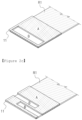
- FIGs. 2a, 2b and 2c provide a view showing a cross-section of the contact portion between the first adsorption pad and the supplied raw material, according to the exemplary shape of the first adsorption pad 11 for describing the structure of the first adsorption pad 11.
- the first adsorption pads according to FIGs. 2a and 2b cover the two edges present in the end portion of the supplied raw material R1, cover the entire width direction of the supplied raw material R1, and secure an area (B) that causes the ultrasonic horn 21 to come into direct contact with the supplied raw material R1 through the opening.
- the opening is not necessarily limited to a hole shape, and may have a shape opened in one direction as shown in FIG. 2a .
- the first upper and lower conveying cylinder 12 is a device for causing the first adsorption pad 11 to move up and down
- the forward and backward conveying cylinder 13 is a device for causing the first adsorption pad 11 to move forward and backward.
- the supplied raw material R1 adsorbed on the first adsorption pad 11 may be positioned to overlap the existing raw material R2 by the first upper and lower conveying cylinder 12 and the forward and backward conveying cylinder 13.
- the first upper and lower conveying cylinder 12 and the forward and backward conveying cylinder 13 do not necessarily operate sequentially, but may operate independently of each other, and thus also may operate simultaneously.
- the bonding unit 20 comprises the ultrasonic horn 21, the second upper and lower conveying cylinder 22, the second adsorption pad 23, the third upper and lower conveying cylinder 24 and the left and right conveying cylinder 25, and may comprise additional components as necessary.
- the ultrasonic horn 21 is a device that transfers the vibration energy of ultrasonic waves to the supplied raw material R1, which is a target for bonding, and bonds the supplied raw material R1 and the existing raw material R2.
- the bonding method using ultrasonic waves is used in consideration of the simplification of the components of the device and the quality such as the bonding force after bonding. Since the bonding method using ultrasonic waves is to melt and bond the object using a wave having a high frequency, the "bonding" in the present invention may mean "welding".
- the frequency of ultrasonic waves applied to the ultrasonic horn 21 for welding by ultrasonic waves can be set differently depending on the material, but may be set within the range of 10 kHz to 50 kHz, preferably 10 kHz to 40 kHz, more preferably 10 kHz to 30 kHz.
- the frequency of ultrasonic waves when welding the separator material by ultrasonic waves, may be set in the range of 10 kHz to 40 kHz, preferably 10 kHz to 30 kHz, more preferably 10 kHz to 20 kHz, and when the protective film material is welded by ultrasonic waves, the frequency of ultrasonic waves may be set in the range of 20 kHz to 50 kHz, preferably 20 kHz to 40 kHz, and more preferably 20 kHz to 30 kHz.
- the second upper and lower conveying cylinder 22 is a device for causing the ultrasonic horn 21 to move up and down. Since the ultrasonic horn 21 is generally located on top of the supplied raw material R1, the ultrasonic horn comes into contact with the supplied raw material R1 by causing the ultrasonic horn 21 to move downward by the second upper and lower conveying cylinder 22.
- the second adsorption pad 23 is a device for adsorbing and fixing the end portion of the existing raw material R2.
- the adsorption method of the second adsorption pad 23 is preferably a vacuum adsorption method using air suction.
- the adhesive property does not need to be as high as the level of the first adsorption pad 11. If the supplied raw materialR1 and the existing raw material R2 overlap, they may be arranged in the order of the second adsorption pad 23, the existing raw material R2, the supplied raw material R1 and the first adsorption pad 11.
- the ultrasonic horn 21 is in contact with the supplied raw material R1 from the side of the first adsorption pad 11, it is not necessary to have an opening for passing the second adsorption pad 23 and the ultrasonic horn 21. Accordingly, the second adsorption pad 23 can easily cover the entire area of the end portion of the existing raw material R2.
- the third upper and lower conveying cylinder 24 is a device for causing the second adsorption pad 23 to move up and down.
- the second adsorption pad 23 moves upward by the third upper and lower conveying cylinder 24, comes into contact with the end portion of the existing raw material R2, and then adsorbs it.
- the second adsorption pad 23 moves downward by the third upper and lower conveying cylinder 24, and is desorbed from the existing raw material R2.
- the left and right conveying cylinder 25 is a device for causing the ultrasonic horn 21 to move to the right or left side.
- the left and right conveying cylinder 25 determines the position where the ultrasonic horn 21 initially comes into contact with the supplied raw material R1, and then determines the direction of welding by ultrasonic waves.
- a forward and backward conveying cylinder for causing the ultrasonic horn 21 to move forward and backward does not particularly exist. This is because the same purpose can be achieved by causing the supplied raw material R1 and the existing raw material R2 to move forward and backward through the rollers of the device.
- the supplied raw material R1 and the existing raw material R2 comprise a separator material and a protective film material, respectively.
- the separator material may be used without limitation as long as it is a separator material for a secondary battery, which is generally used in the relevant technical field, and exemplarily, polyolefin-based polymers such as polyethylene and polypropylene may be used.
- the separator material is put into the production line of the separator material, but the separator material is generally distributed and supplied in the form of a roll.
- the protective film material is attached to one side of the separator material to separate and protect the raw material.
- the protective film material may be used without limitation as long as it is generally used in the relevant technical field, and exemplarily, polyethylene terephthalate (PET) may be used.
- PET polyethylene terephthalate
- a process of removing the protective film material from the separator material is required, and the raw material supply device according to the present invention can automatically perform even the process of removing and recovering the protective film material from the separator material.
- the constitution of the conveying unit 10 comprising the first adsorption pad 11, the first upper and lower conveying cylinder 12 and the forward and backward conveying cylinder 13, and the constitution of the bonding unit 20 comprising the ultrasonic horn 21, the second upper and lower conveying cylinder 22, the second adsorption pad 23, the third upper and lower conveying cylinder 24 and the left and right conveying cylinder 25 should exist by two.
- the same two constitutions are each separated up and down and are arranged symmetrically about a central axis. This can be confirmed through the conveying unit 10 and the bonding unit 20 as shown in FIG. 1 . Since the upper and lower portions are arranged symmetrically with respect to the central axis, the lower portion is described in an inverted state up and down from the case of the upper portion.
- the second adsorption pad 23 supports the bottom, and on it, the existing raw material R2, the supplied raw material R1, and the first adsorption pad 11 are arranged in this order, and the ultrasonic horn 21 moves from top to bottom, passes through the opening of the first adsorption pad 11 and comes into contact with the supplied raw material R1.
- the second adsorption pad 23 is located at the top, and below it, the existing raw material R2, the supplied raw material R1, and the first adsorption pad 11 are arranged in this order, and the ultrasonic horn 21 moves from bottom to top, passes through the opening of the first adsorption pad 11 and comes into contact with the supplied raw material R1.
- the separator material (R2a) discharged through the bonding unit 20 is put into the production line of the secondary battery and the protective film material (R2b) discharged through the bonding unit 20 is recovered in the form of a roll, it may be preferable that for operational efficiency, the separator material is separated from the top of the device (D3) and the protective film material is separated from the bottom of the device (D4).
- FIGs. 3a , 3b , 3c , 3d and 3e provide views showing each process in order to explain in detail the process of driving the raw material supply device for the separator of the secondary battery according to an embodiment of the present invention, wherein the supplied raw material R1 coated with the protective film material on the separator material is used.
- FIG. 3a shows a state in which the supplied raw material R1 is supplied, and the two first adsorption pads 11 are adsorbed to the separator material and the protective film material, respectively.
- the protective film material may be supplied so that it is located below.
- FIG. 3b shows a state in which the supplied raw material R1 is separated into the separator material and the protective film material due to the up and down movement of the two first adsorption pads 11.
- the supplied raw material R1 is separated into a separator material and a protective film material due to the up and down movement of the two first adsorption pads 11 by the first upper and lower conveying cylinder 12, but it is distinct from the forward and backward movement of the first adsorption pad 11, and thus does not have to proceed sequentially.
- the upper and lower movement and the forward and backward movement of the first adsorption pad 11 may be proceeded simultaneously, and if the supplied raw material R1 moves to the existing raw material R2 in the shortest linear distance, the load applied to the material can be reduced.
- the separator material and the protective film material if the entire adsorption area of the first adsorption pad 11 and the separator material or the protective film material are separated at once, the material may be damaged, and thus the design of the first adsorption pad 11 can be changed so that it can be sequentially separated from the starting line in the longitudinal direction (MD) of the supplied raw material R1.
- the first adsorption pad 11 is composed of several nodes instead of one so that it has a structure that can be sequentially separated from the starting line of the supplied raw material R1, or the first adsorption pad 11 may have a structure in which the adsorption of the first adsorption pad 11 is not applied with the same intensity over the entire adsorption surface, but is sequentially applied from the part close to the starting line of the supplied raw material R1.
- FIG. 3c shows a state in which the end portion of the supplied raw material R1 and the end portion of the existing raw material R2 are positioned to overlap by causing the supplied raw material R1 separated into the separator material and the protective film material to move forward and backward of the first adsorption pad 11.
- the supplied raw material R1 is supplied in the form of a roll, it has a certain level of tension suitable for application to the production line. Even through the raw material supply device according to the present invention, it is desirable that such tension be maintained.
- the supplied raw material R1 is adsorbed on the first adsorption pad 11 and moves to the existing raw material R2, a change in tension may occur.
- the tension of the supplied raw material can be maintained at 90% to 110%, based on the tension of the supplied raw material in the form of a roll.
- the end portion of the supplied raw material R1 and the end portion of the existing raw material R2 may overlap at 5 mm to 20 mm in the longitudinal direction by the forward and backward movement of the first adsorption pad 11.
- the end portion of the supplied raw material R1 and the end portion of the existing raw material R2 can be strongly bonded without breaking, not only in the raw material supply device according to the present invention, but also in the production line of the secondary battery, the smaller the overlapping area of the end portion of the supplied raw material R1 and the end portion of the existing raw material R2, the more preferable.
- the raw material supply device according to the present invention when the supplied raw material R1 and the existing raw material R2 are bonded, if the welding by ultrasonic waves is used, a strong bonding force can be expressed even with a small welding area, and thus the overlapping area of the supplied raw material R1 and the existing raw material R2 can be set small.
- FIG. 3d shows a state in which the supplied raw material R1 and the existing raw material R2 are welded by placing the ultrasonic horn 21 on the supplied raw material R1 in the overlapping portion of the supplied raw material R1 and the existing raw material R2 and applying ultrasonic waves to the ultrasonic horn 21.
- the ultrasonic horn 21 passes through the opening of the first adsorption pad 11, and then is positioned so as to be in contact with the supplied raw material R1 on the other surface of the overlapping portion of the supplied raw material R1 and the existing raw material R2.
- a specific driving direction of the ultrasonic horn 21 after this will be described supplementarily with reference to FIG. 4a and 4b .
- FIG. 3e shows the operating state of the device after bonding the supplied raw material R1 and the existing raw material R2.
- the first adsorption pad 11 and the second adsorption pad 23 desorb the supplied raw material R1 and the existing raw material R2, respectively, and move to the initial position where the flow of the raw material is not obstructed.
- the ultrasonic horn 21 also moves upward and waits until the next replacement of the raw material. If the supplied raw material is all exhausted, a new supplied raw material is introduced in a state where the end is fixed by the second adsorption pad 23, and the processes starting from FIG. 3a are repeated again.
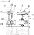
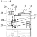
- FIGs. 4a and 4b provide views showing a top view ( FIG. 4a ) and a left side view ( FIG. 4b ) of an exemplary bonding unit when the supplied raw material R1 and the existing raw material R2 are welded by ultrasonic waves with the ultrasonic horn 21 in order to describe the welding process by ultrasonic waves in the bonding unit 20 in detail.
- the ultrasonic horn 21 is located in contact with the supplied raw material R1 at one end of the opening of the first adsorption pad 11, and welds the supplied raw material R1 and the existing raw material R2 while moving left and right (D5) in the width direction by the left and right conveying cylinder 25.
- the left and right movement can be performed repeatedly, and it is possible to repeatedly perform ultrasonic welding in the same position by the repeated left and right movement, and an additional ultrasonic welding can be performed by causing the overlapping part to move forward and backward through the roller of the device.
- the ultrasonic welding is performed to cover the widest possible range based on the width direction.
- the raw material supply device may comprise additional components as shown in FIG. 1 if necessary.
- additional components components closely related to the functionality of the device will be supplementarily described below, but the additional components are not necessarily limited to these components.
- the raw material supply device further comprises a plurality of rollers 31 between the supplied raw material in the form of a roll and the conveying unit 10.
- a movement path of the supplied raw material may be determined by the plurality of rollers 31.
- the plurality of rollers 31 help the supplied raw material to maintain a certain level of tension by causing the movement path of the supplied raw material to form a zigzag pattern.
- These rollers 31 are also utilized to control the movement path of the separator material or the protective film material discharged through the bonding unit 20.
- the raw material supply device further comprises an ultrasonic generator 32 for generating ultrasonic waves so as to apply ultrasonic waves to the ultrasonic horn 21.
- the ultrasonic generator 32 serves to convert electrical energy into a form suitable for application to the ultrasonic horn. If the ultrasonic generator 32 can implement at a level of vibration energy capable of achieving the object of the present invention in the ultrasonic horn, the type thereof is not particularly limited.
- the raw material supply device further includes a pneumatic controller 33 and a pneumatic signal generator 34.
- a pneumatic controller 33 controls the raw material supply device.
- components such as the conveying cylinder and the adsorption pad can be driven by pneumatic pressure, and this pneumatic pressure is controlled by the pneumatic controller 33 and the pneumatic signal generator 34.
Landscapes
- Chemical & Material Sciences (AREA)
- Chemical Kinetics & Catalysis (AREA)
- Electrochemistry (AREA)
- General Chemical & Material Sciences (AREA)
- Engineering & Computer Science (AREA)
- Manufacturing & Machinery (AREA)
- Inorganic Chemistry (AREA)
- Cell Separators (AREA)
Applications Claiming Priority (2)
| Application Number | Priority Date | Filing Date | Title |
|---|---|---|---|
| KR1020210048930A KR102781567B1 (ko) | 2021-04-15 | 2021-04-15 | 이차전지의 분리막용 원료 공급 장치 |
| PCT/KR2022/005454 WO2022220637A1 (ko) | 2021-04-15 | 2022-04-15 | 이차전지의 분리막용 원료 공급 장치 |
Publications (3)
| Publication Number | Publication Date |
|---|---|
| EP4164015A1 true EP4164015A1 (de) | 2023-04-12 |
| EP4164015A4 EP4164015A4 (de) | 2025-02-26 |
| EP4164015B1 EP4164015B1 (de) | 2026-01-21 |
Family
ID=83640834
Family Applications (1)
| Application Number | Title | Priority Date | Filing Date |
|---|---|---|---|
| EP22788492.1A Active EP4164015B1 (de) | 2021-04-15 | 2022-04-15 | Materialzufuhrvorrichtung für sekundärbatterieseparator |
Country Status (5)
| Country | Link |
|---|---|
| US (1) | US12103801B2 (de) |
| EP (1) | EP4164015B1 (de) |
| KR (1) | KR102781567B1 (de) |
| CN (1) | CN116096662A (de) |
| WO (1) | WO2022220637A1 (de) |
Cited By (1)
| Publication number | Priority date | Publication date | Assignee | Title |
|---|---|---|---|---|
| EP4596473A1 (de) * | 2024-01-31 | 2025-08-06 | TBS Engineering Limited | Verfahren und system zum verbinden von streifen eines batteriegitters |
Families Citing this family (6)
| Publication number | Priority date | Publication date | Assignee | Title |
|---|---|---|---|---|
| US12612278B2 (en) * | 2022-06-03 | 2026-04-28 | GAMBINI S.p.A. | Unwinder, in particular for unwinding reels of paper, semi-automatic plant comprising such unwinder and process for unwinding reels |
| KR102641960B1 (ko) * | 2023-09-05 | 2024-02-28 | (주)아이케이텍 | 이차전지용 동박 연속도금라인의 어큐뮬레이터 조립체 |
| WO2025075431A1 (ko) * | 2023-10-06 | 2025-04-10 | 주식회사 엘지에너지솔루션 | 전극 조립체 제조 장치 및 전극 조립체 제조 방법 |
| KR20250051422A (ko) | 2023-10-10 | 2025-04-17 | 주식회사 엘지화학 | 리드필름과 메인필름 간 자동연결장치 |
| KR20250162068A (ko) * | 2024-05-10 | 2025-11-18 | 주식회사 엘지에너지솔루션 | 이차 전지용 분리막 공급 장치 및 이차 전지용 분리막 공급 방법 |
| WO2026005343A1 (ko) * | 2024-06-24 | 2026-01-02 | 주식회사 엘지에너지솔루션 | 분리막 주행 장치 |
Family Cites Families (17)
| Publication number | Priority date | Publication date | Assignee | Title |
|---|---|---|---|---|
| GB1314572A (en) * | 1970-02-04 | 1973-04-26 | Ilford Ltd | Joining lengths of plastic film material |
| JPH09194090A (ja) | 1996-01-12 | 1997-07-29 | Toshiba Battery Co Ltd | オートスプライサ装置 |
| AT500126B1 (de) * | 2003-11-04 | 2007-05-15 | Deininger Karl Dipl Ing | Verfahren zum wechseln von schlauchrollen, insbesondere für seitenfaltenschläuche |
| JP4316414B2 (ja) | 2004-04-13 | 2009-08-19 | 大王製紙株式会社 | スプライス装置及びスプライス方法 |
| KR100915269B1 (ko) | 2008-09-01 | 2009-09-03 | 이계설 | 리튬 이온전지의 분리막 연결장치 및 방법 |
| JP5294277B2 (ja) * | 2010-07-28 | 2013-09-18 | 株式会社不二鉄工所 | シート接合方法ならびに接合装置 |
| JP5908231B2 (ja) | 2011-08-22 | 2016-04-26 | 株式会社トパック | 自動包装機の継ぎ装置 |
| JP5943704B2 (ja) * | 2012-05-18 | 2016-07-05 | 富士機械工業株式会社 | ウェブ接続装置 |
| KR102266662B1 (ko) * | 2012-05-23 | 2021-06-21 | 가부시키가이샤 니콘 | 디바이스 제조 방법 |
| KR101956930B1 (ko) * | 2013-02-25 | 2019-03-11 | 삼성에스디아이 주식회사 | 이차 전지용 권취 설비의 자재 자동 교환 장치 |
| JP2015015115A (ja) * | 2013-07-03 | 2015-01-22 | 株式会社東京機械製作所 | 電極シートの作成装置及び作成方法 |
| KR101705191B1 (ko) | 2016-09-21 | 2017-02-10 | (주) 씨오텍 | 맞대기 이음 방식의 원단 자동연결장치 |
| KR101873198B1 (ko) * | 2016-12-15 | 2018-08-02 | (주)피토 | 2차전지 제조용 소재 연결장치 |
| KR101873197B1 (ko) | 2016-12-15 | 2018-07-02 | (주)피토 | 2차전지 제조용 소재 연결장치 |
| KR101892583B1 (ko) | 2018-02-21 | 2018-08-28 | 김태완 | 이차전지용 분리막 접합장치 및 작동방법 |
| KR102248303B1 (ko) | 2019-07-16 | 2021-05-04 | 주식회사 필옵틱스 | 이차전지용 분리막의 접합장치 |
| KR102758636B1 (ko) | 2019-10-24 | 2025-01-22 | 삼성전자주식회사 | 심전도 데이터를 이용한 사용자 검증 장치 및 그 방법 |
-
2021
- 2021-04-15 KR KR1020210048930A patent/KR102781567B1/ko active Active
-
2022
- 2022-04-15 EP EP22788492.1A patent/EP4164015B1/de active Active
- 2022-04-15 US US18/017,737 patent/US12103801B2/en active Active
- 2022-04-15 WO PCT/KR2022/005454 patent/WO2022220637A1/ko not_active Ceased
- 2022-04-15 CN CN202280005917.3A patent/CN116096662A/zh active Pending
Cited By (2)
| Publication number | Priority date | Publication date | Assignee | Title |
|---|---|---|---|---|
| EP4596473A1 (de) * | 2024-01-31 | 2025-08-06 | TBS Engineering Limited | Verfahren und system zum verbinden von streifen eines batteriegitters |
| GB2637722A (en) * | 2024-01-31 | 2025-08-06 | Tbs Eng Ltd | Method and system for joining strips of battery grid |
Also Published As
| Publication number | Publication date |
|---|---|
| CN116096662A (zh) | 2023-05-09 |
| WO2022220637A1 (ko) | 2022-10-20 |
| KR102781567B1 (ko) | 2025-03-17 |
| EP4164015B1 (de) | 2026-01-21 |
| US12103801B2 (en) | 2024-10-01 |
| EP4164015A4 (de) | 2025-02-26 |
| KR20220142640A (ko) | 2022-10-24 |
| US20230264913A1 (en) | 2023-08-24 |
Similar Documents
| Publication | Publication Date | Title |
|---|---|---|
| EP4164015A1 (de) | Materialzufuhrvorrichtung für sekundärbatterieseparator | |
| KR102414044B1 (ko) | 전지 셀에 부착 가능한 접착 테이프용 테이핑 장치 및 테이핑 방법 | |
| JP4199008B2 (ja) | 自動化されたリチウム2次電池製造システム用パッキング装置 | |
| KR101090076B1 (ko) | 2차 전지의 전극탭 필름 열융착장치 | |
| US7055570B2 (en) | Automated manufacturing system of lithium secondary battery | |
| EP3165321A1 (de) | Verfahren zur verbindung von verbundstoffmaterialien und vorrichtung zur verbindung von verbundstoffmaterialien | |
| KR102847359B1 (ko) | 전극 조립체 제조장치와, 이를 통해 제조된 전극 조립체 및 이차전지 | |
| CN107073639B (zh) | 超声波接合装置和超声波接合方法 | |
| US9793571B2 (en) | Apparatus for bonding separators in electrical devices | |
| KR102253132B1 (ko) | 2차 전지용 단위 셀 제조 방법, 장치 및 시스템 | |
| KR102942992B1 (ko) | 배터리 셀의 구성 요소를 적층하기 위한 방법 및 장치 | |
| KR20220008629A (ko) | 테이프 제거 장치 | |
| EP4507118A1 (de) | Filmbefestigungsvorrichtung für batteriezelle | |
| KR20150049474A (ko) | 전극 조립체 권취 장치 및 전극 조립체 권취 방법 | |
| KR102404678B1 (ko) | 셀 스택 제조용 분리막 공급피더 | |
| US20230286765A1 (en) | Roll type raw material supply device | |
| KR101794382B1 (ko) | 유닛셀 공급장치 | |
| KR20200056191A (ko) | 전극조립체의 제조방법 및 제조장치 | |
| KR102962584B1 (ko) | 롤 형태 원료 공급 장치 | |
| KR20230109266A (ko) | 롤 형태 원료 공급 장치 | |
| EP4550502A1 (de) | Elektrodenversorgungsvorrichtung, elektrodenanordnungsherstellungsvorrichtung damit, elektrodenversorgungsverfahren und elektrodenanordnungsherstellungsverfahren damit | |
| KR102919488B1 (ko) | 이차전지의 파우치 스플라이싱 장치 | |
| KR102876577B1 (ko) | 이차전지용 오토 스플라이싱 장비 및 그 방법 | |
| EP4496051B1 (de) | Formungsvorrichtung für beutelartige batteriezelle | |
| CN120606158A (zh) | 一种用于锂电池超声波焊接的定位装置 |
Legal Events
| Date | Code | Title | Description |
|---|---|---|---|
| STAA | Information on the status of an ep patent application or granted ep patent |
Free format text: STATUS: THE INTERNATIONAL PUBLICATION HAS BEEN MADE |
|
| PUAI | Public reference made under article 153(3) epc to a published international application that has entered the european phase |
Free format text: ORIGINAL CODE: 0009012 |
|
| STAA | Information on the status of an ep patent application or granted ep patent |
Free format text: STATUS: REQUEST FOR EXAMINATION WAS MADE |
|
| 17P | Request for examination filed |
Effective date: 20230103 |
|
| AK | Designated contracting states |
Kind code of ref document: A1 Designated state(s): AL AT BE BG CH CY CZ DE DK EE ES FI FR GB GR HR HU IE IS IT LI LT LU LV MC MK MT NL NO PL PT RO RS SE SI SK SM TR |
|
| DAV | Request for validation of the european patent (deleted) | ||
| DAX | Request for extension of the european patent (deleted) | ||
| A4 | Supplementary search report drawn up and despatched |
Effective date: 20250127 |
|
| RIC1 | Information provided on ipc code assigned before grant |
Ipc: B65H 21/00 20060101ALI20250121BHEP Ipc: H01M 50/403 20210101ALI20250121BHEP Ipc: H01M 50/46 20210101ALI20250121BHEP Ipc: H01M 50/451 20210101ALI20250121BHEP Ipc: H01M 50/449 20210101ALI20250121BHEP Ipc: H01M 50/417 20210101ALI20250121BHEP Ipc: H01M 50/406 20210101ALI20250121BHEP Ipc: B65H 23/26 20060101ALI20250121BHEP Ipc: B65H 20/16 20060101ALI20250121BHEP Ipc: B65H 19/18 20060101ALI20250121BHEP Ipc: H01M 10/04 20060101AFI20250121BHEP |
|
| RIC1 | Information provided on ipc code assigned before grant |
Ipc: H01M 10/04 20060101AFI20250701BHEP Ipc: B65H 19/18 20060101ALI20250701BHEP Ipc: B65H 20/16 20060101ALI20250701BHEP Ipc: B65H 23/26 20060101ALI20250701BHEP Ipc: H01M 50/406 20210101ALI20250701BHEP Ipc: H01M 50/417 20210101ALI20250701BHEP Ipc: H01M 50/449 20210101ALI20250701BHEP Ipc: H01M 50/451 20210101ALI20250701BHEP Ipc: H01M 50/46 20210101ALI20250701BHEP Ipc: H01M 50/403 20210101ALI20250701BHEP Ipc: B65H 21/00 20060101ALI20250701BHEP Ipc: B23K 20/10 20060101ALI20250701BHEP |
|
| GRAP | Despatch of communication of intention to grant a patent |
Free format text: ORIGINAL CODE: EPIDOSNIGR1 |
|
| STAA | Information on the status of an ep patent application or granted ep patent |
Free format text: STATUS: GRANT OF PATENT IS INTENDED |
|
| INTG | Intention to grant announced |
Effective date: 20250901 |
|
| GRAS | Grant fee paid |
Free format text: ORIGINAL CODE: EPIDOSNIGR3 |
|
| GRAA | (expected) grant |
Free format text: ORIGINAL CODE: 0009210 |
|
| STAA | Information on the status of an ep patent application or granted ep patent |
Free format text: STATUS: THE PATENT HAS BEEN GRANTED |
|
| AK | Designated contracting states |
Kind code of ref document: B1 Designated state(s): AL AT BE BG CH CY CZ DE DK EE ES FI FR GB GR HR HU IE IS IT LI LT LU LV MC MK MT NL NO PL PT RO RS SE SI SK SM TR |
|
| REG | Reference to a national code |
Ref country code: CH Ref legal event code: F10 Free format text: ST27 STATUS EVENT CODE: U-0-0-F10-F00 (AS PROVIDED BY THE NATIONAL OFFICE) Effective date: 20260121 |
|
| REG | Reference to a national code |
Ref country code: DE Ref legal event code: R096 Ref document number: 602022028916 Country of ref document: DE |
|
| REG | Reference to a national code |
Ref country code: IE Ref legal event code: FG4D |
|
| P01 | Opt-out of the competence of the unified patent court (upc) registered |
Free format text: CASE NUMBER: UPC_APP_0004922_4164015/2026 Effective date: 20260211 |
|
| PGFP | Annual fee paid to national office [announced via postgrant information from national office to epo] |
Ref country code: GB Payment date: 20260324 Year of fee payment: 5 |
|
| PGFP | Annual fee paid to national office [announced via postgrant information from national office to epo] |
Ref country code: BE Payment date: 20260323 Year of fee payment: 5 |
|
| PGFP | Annual fee paid to national office [announced via postgrant information from national office to epo] |
Ref country code: FR Payment date: 20260323 Year of fee payment: 5 |