EP4164819B1 - Cintreuse de panneaux pour le pliage de tôles - Google Patents
Cintreuse de panneaux pour le pliage de tôles Download PDFInfo
- Publication number
- EP4164819B1 EP4164819B1 EP21773377.3A EP21773377A EP4164819B1 EP 4164819 B1 EP4164819 B1 EP 4164819B1 EP 21773377 A EP21773377 A EP 21773377A EP 4164819 B1 EP4164819 B1 EP 4164819B1
- Authority
- EP
- European Patent Office
- Prior art keywords
- drive
- bending beam
- bending
- panel bender
- drive guide
- Prior art date
- Legal status (The legal status is an assumption and is not a legal conclusion. Google has not performed a legal analysis and makes no representation as to the accuracy of the status listed.)
- Active
Links
Images

Classifications
-
- B—PERFORMING OPERATIONS; TRANSPORTING
- B21—MECHANICAL METAL-WORKING WITHOUT ESSENTIALLY REMOVING MATERIAL; PUNCHING METAL
- B21D—WORKING OR PROCESSING OF SHEET METAL OR METAL TUBES, RODS OR PROFILES WITHOUT ESSENTIALLY REMOVING MATERIAL; PUNCHING METAL
- B21D5/00—Bending sheet metal along straight lines, e.g. to form simple curves
- B21D5/04—Bending sheet metal along straight lines, e.g. to form simple curves on brakes making use of clamping means on one side of the work
-
- B—PERFORMING OPERATIONS; TRANSPORTING
- B21—MECHANICAL METAL-WORKING WITHOUT ESSENTIALLY REMOVING MATERIAL; PUNCHING METAL
- B21D—WORKING OR PROCESSING OF SHEET METAL OR METAL TUBES, RODS OR PROFILES WITHOUT ESSENTIALLY REMOVING MATERIAL; PUNCHING METAL
- B21D5/00—Bending sheet metal along straight lines, e.g. to form simple curves
- B21D5/02—Bending sheet metal along straight lines, e.g. to form simple curves on press brakes without making use of clamping means
- B21D5/0272—Deflection compensating means
Definitions
- the invention relates to a panel bender for bending sheet metal.
- the invention relates to a panel bender for bending sheet metal according to claim 1.
- the bending beam With panel benders, the bending beam is moved using a wide variety of complicated mechanisms.
- the bending beam must be movable in the vertical and horizontal direction and generate the required force.
- the vertical, long-stroke movement is usually carried out using cylinders or screw drives.
- the horizontal direction requires a relatively short stroke with great force for application and is implemented using various transmissions, such as wedge systems, eccentrics or superimposed rotary connections. Such implementations are difficult to scale.
- AT 372883 B discloses a device for folding a sheet metal panel, wherein the drive of the bending tool acts approximately parallel to the clamping plane being supported on the carrier of the holding punch serving as a counter tool.
- Document EP 2 691 190 A1 discloses a panel bender having a C-shaped blade holder structure.
- the blade holder structure is slidably arranged on upper and lower wedge-shaped slides which can be moved along vertical guides by associated actuators.
- the object of the invention is to avoid the disadvantages of the prior art and to provide an improved panel bender.
- the panel bender according to the invention for bending sheet metal by means of at least one bending tool arranged on a bending beam, the bending beam extending along a direction, comprises
- At least one second drive is arranged in each drive guide unit, wherein the at least one second drive engages the bending beam to move the same in the second direction.
- Suitable guides on the second drives of the vertical adjustment enable the angle of the bending beam to be adjusted.
- small short-stroke cylinders also electromechanical or similar
- These units are connected horizontally to the bending beam and allow both an almost flat introduction of force and a particularly advantageous use of the rigidity of the unit. Any deformations that occur can be minimised by using the available space inside the machine body with the appropriate use of material. The entire construction optimises the resulting stresses through reaction forces.
- the short-stroke cylinders do not affect the vertical movement/guidance in any way and allow the technologically required circular movement of the bending beam to be implemented on the control side.
- the panel bender according to the invention or the swivel bending machine has the advantage that vertical and horizontal movements are mechanically separated and overlapping is excluded. Both the vertical and the horizontal guidance of the bending beam is close to the force flow due to the structure described and enables the machine to be designed in accordance with the rigidity. The entire construction optimises the resulting stresses through reaction forces. Furthermore, a significantly simplified and also more precise production of the machine body is possible; only the front side is machined after clamping.
- the invention simplifies the entire structure of a panel bender since additional drives and guides are saved and there are still possibilities for adjustment and dynamic control. Installation and service times are significantly reduced in comparison, and simple interchangeability is guaranteed in terms of design.
- Scaling the machines is significantly simplified according to the invention. If more bending force is required, for example with longer machine lengths or when bending thicker sheets, the number of drives, for example in the form of short-stroke cylinders, can be increased.
- a two-fold increase in accuracy can be achieved.
- increased accuracy is already achieved in the manufacture of the machine body since no re-clamping or retooling is required since only a front side of the machine body has to be processed.
- decoupling the two movements or axes of movement increased accuracy is achieved during operation of the panel bender.
- first direction runs vertically and that the second direction runs horizontally. This arrangement allows an advantageous introduction and absorption of forces and torques.
- the drive guide unit has a substantially C-shaped base body, wherein an inner contour of the drive guide unit at least partially corresponds to an outer contour of the bending beam.
- the bending beam can be fitted precisely into the drive guide unit, also in a form-fitting or force-fitting manner.
- an infeed element is provided as a support bearing for the bending beam in the drive guide unit, wherein the infeed element can be attached to one end of a lower leg of the C-shaped base body.
- the drive guide unit In the upper area (also possible in the lower area), the drive guide unit can be attached in a floating manner.
- a further support bearing such as an infeed element can be attached, which optimally dissipates moments when bending sheet metal.
- This guide can advantageously be advanced by means of a wedge adjustment and reached from the front.
- At least one first drive is provided on the machine body, wherein the at least one first drive engages at least one drive guide unit to move the same.
- the bending beam can be suspended from two or more optimally rigid drive guide units.
- the guide can be in the horizontal direction directly below and exactly in the power flow of this receptacle.
- the vertical bending beam guide of the now technically separate movements can be attached directly to the machine body with sliding or rolling element guides (or similar).
- the drive guide unit with the embedded bending beam is guided directly.
- the simultaneous entrainment of the bending beam and the horizontally applied bending force in the vertical direction is also advantageous.
- the control effort is significantly reduced if the same parameters can be used for the horizontal movement-regardless of the vertical position.
- the second drives can be operated independently of one another.
- the at least one second drive is arranged along the first direction in an axis of the at least one first drive.
- the second drive can thus be located directly above or below the first drive, for example as an extension of a movement axis of the first drive.
- multiple drive guide units are arranged along the direction along which the bending beam extends and that the bending beam is arranged in the several drive guide units.
- the bending beam can be positioned horizontally or tilted.
- a first drive is assigned to each of the multiple drive guide units. This enables a more precise control and a more uniform introduction of force.
- an extension of the bending beam in the direction of the second direction is smaller than an extension of the bending beam in the direction of the first direction.
- the bending line is arranged close to the introduction of force so that torques can be better absorbed.
- warpage is reduced when heated.
- a controller is provided for controlling the at least one first drive and the at least one second drive and in that the controller is arranged to align the at least one bending tool arranged on the bending beam in the first and second directions along a bending line.
- This can be a parallel orientation.
- a rotary movement of the bending beam can be achieved by individual activation of the drives, which allows bends that were previously impossible to carry out.
- a machine body structure of this type enables, among other things, a horizontal adjustment of the parallelism of the entire bending beam to the bending line.
- the drives are operated, for example in the form of a short-stroke cylinder per unit, in parallel and independently of one another on the outside of the machine. Deviations in parallelism can thus be compensated for and avoided in a position-controlled manner, for example with measuring systems and corresponding controls. For example, one side can be positioned a little further forward than the other side.
- the vertical parallelism setting here the suspension of the bending beam on two or more externally attached and separately controllable drives such as cylinders enables parallelism to be set in the event of deviations.
- Figure 1 shows a perspective view of a panel bender 10 with a machine body 12 which can be attached to a floor by means of feet 14.
- the machine body 12 extends in a first direction z, which runs vertically, a second direction y, which runs horizontally, and a third direction x, which runs horizontally and perpendicular to the other two directions z and y.
- a bending line, along which sheet metal parts are bent by the panel bender 10, runs in the x direction.
- Bending is carried out by means of a bending beam 16, which is mounted on the machine body 12 so as to be movable in the z and y directions.
- the bending beam 16 is supported here on at least two drive guide units 18, which can be moved in the z direction on the machine body 12 and are each driven by a first drive 20.
- the drive guide units 18, of which more than two can be provided, are arranged along the x direction.
- the bending beam 16 is movably supported in the drive guide units 18, specifically in the y direction.
- the two movement axes in the z and y directions are technically separate movements and thus decoupled from one another, which simplifies both the construction and the control and also increases the accuracy.
- a hold-down device for a workpiece is movably held on a front side of the machine body and can be moved in the z direction on the machine body by two drives.
- the hold-down device is not shown here.
- Figure 2 shows a perspective view of the machine body 12 with a front side 22 which lies in the x-z plane.
- three guide receptacles 24 are provided here, which extend in the z direction.
- the guide receptacles 24 are recesses in the machine body 12 and here have guide means 26 which are attached to the front side 22 of the machine body 12.
- the guide means 26 can be designed as slide rails, for example.
- each of the guide receptacles 24 there is a drive guide unit 18 which is driven by a first drive 20.
- the drive guide unit 18 has a substantially C-shaped base body 28 with an upper leg 30 and a base part 32. Only the two outermost drive guide units 18 are driven while the one or more inner drive guide units, i.e., arranged between the two outermost drive guide units 18, are not driven. Alternatively, it is possible that the inner drive guide units are also driven.
- a piston or cylinder of the first drive 20 engages an upper leg 30 of the drive guide unit 18.
- the guide means 26 can secure the drive guide unit 18 in the recess of the guide receptacles 24 against removal.
- further guide means 34 for example in the form of slide rails, are provided, which interact with the guide means 26.
- three second drives 36 in the form of short-stroke cylinders are arranged here.
- the three second drives 36 are arranged along the z direction and can be arranged in an axis or an extension of the axis of the first drive 20.
- the second drives 36 exert an actuating force in the y direction.
- the second drives 36 engage the bending beam in order to move the same and allow an almost flat introduction of force.
- Scaling the machines is significantly simplified according to the invention. If more bending force is required, for example in the case of larger machine lengths or the bending of thicker sheets, the number of second drives 36 or the short-stroke cylinders can be increased.
- Each of the three short-stroke cylinders shown here can be referred to as a second drive 36.
- the three short-stroke cylinders shown here can be referred to collectively as a second drive 36.
- the first drive(s) 20 move the drive guide units 18 in the vertical direction z.
- the second drives 36 are thus moved along with the drive guide units 18.
- the second drives 36 can be moved independently and decoupled from the first drives 20.
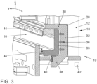
- Figure 3 shows a perspective partial sectional representation of the panel bender 10 with a bending beam 16.
- the bending beam 16 is received and held in the drive guide units 18.
- the substantially C-shaped base body 28 of the drive guide unit 18 has an inner contour which at least partially corresponds to an outer contour of the bending beam 16.
- the bending beam 16 rests against the upper leg 30 of the base body 28 or the drive guide unit 18.
- a back or rear side 33 of the bending beam 16 runs parallel to the base part 32 in which the second drives 36 are received in recesses.
- an underside of the bending beam 16 runs parallel to a lower leg 38 of the drive guide unit 18.
- the upper leg 30 and the lower leg 38 extend from the base part 32.
- a receiving space for the bending beam 16 is formed between the two legs 30, 38.
- An infeed element 40 is provided as a support bearing for the bending beam 16 in the drive guide unit 18, wherein the infeed element 40 is attached to one end of the lower leg 38 of the C-shaped base body 28.
- the infeed element 40 optimally dissipates torques when bending sheet metal, in particular with negative bending.
- the infeed element 40 can easily be reached from the front and fastened, for example, by means of a screw connection.
- An extension of the bending beam 16 in the direction of the second direction is smaller here than an extension of the bending beam 16 in the direction of the first direction. In this way, torques can be reduced by the second direction.
- a plurality of drive guide units 18 can be arranged along the third direction, wherein the bending beam 16 is arranged in the multiple drive guide units 18.
- Station operation can be enabled between two drive guide units 18, so that, for example, multiple work steps can be carried out along the bending line or in the third direction.
- a controller 42 of the panel bender 10 is used to control the at least one first drive 20 and the at least one second drive 36 and is only shown schematically here.
- the controller 42 is connected to the drives 20, 36 and possibly sensors and further controllers.
- the controller 42 is configured to align a bending tool 44 arranged on the bending beam 16 in the first and second directions along a bending line. Sensors for measuring a deformation of the bending beam during a bending process can provide measured values. Based on the measured values, manipulated variables for the first and/or the second drive to compensate for the deformation can be derived. The controller 42 can then control the drive(s) in accordance with the manipulated variables.
- the manipulated variables for the first drive 20 and the second drive 36 are also independent of one another.
- the simple and modular construction allows a simple production and a simple construction of the panel bender 10.
- the machine body 12 only has to be clamped once, since it only has to be machined from the front.
- the assembly of the drive guide units 18, the bending beam 16 and the first drives 20 is only necessary from the front.
- the components can easily be scaled for larger or smaller variants of the panel bender 10 or larger or smaller forces, so that a modular system is possible. This is made possible by the decoupling of the two axes of movement, i.e., of the at least one first drive 20 and the at least one second drive 36.
- the panel bender presented here enables the two movement axes in the z and y directions to be technically separate movements and thus decoupled from each other, which simplifies both the construction and the control and also increases the accuracy.
- the bending beam With panel benders, the bending beam is moved using a wide variety of complicated mechanisms.
- the bending beam must be movable in the vertical and horizontal direction and generate the required force. Bending reaction forces that occur, especially in the horizontal direction, cannot be prevented or compensated, or only with great difficulty, by means of control technology due to the structural drive structure. As a result, material deformations on the bending beam have a negative impact on the bending result.
- the object of the invention is now to avoid the disadvantages of the prior art and to provide an improved panel bender or an improved method for crowning a bending beam.
- This object is achieved by a panel bender or a method for crowning a bending beam.
- the panel bender according to the invention with dynamic crowning for bending sheet metal by means of at least one bending tool arranged on a bending beam, wherein the bending beam extends along one direction, comprises a machine body,
- At least the second drives can form a crowning unit to compensate for a deformation of the bending beam.
- the crowning unit is connected to the bending beam in the vertical direction and thus moves with it. Positive and negative bends are thus crowned in the same way and allow a simplified control.
- the design allows the two axes of movement, i.e., of the at least one first drive and the second drives, to be decoupled.
- the second drives compensate for the deformation, i.e., the crowning.
- the second drives take over the infeed of the bending beam in the horizontal direction.
- the crowning component can be superimposed on the infeed component of the second drive.
- the crowning component is completely independent of the at least one first drive.
- At least one second drive is connected to the bending beam.
- Force generation and position control of the horizontal direction of movement of the bending beam can be implemented via externally connected crowning units and guided accordingly.
- a centrally connected crowning unit can act in addition to the positioning described and can generate additional bending force under pressure, but also position-controlled. This minimises the general deformation of the bending beam due to the reduced support width and reaction-related deviations in the horizontal direction are reduced.
- the introduction of a higher force corresponding to the deformation in the middle of the bending beam even compensates for the deviations and allows an optimal bending result.
- This unit further improves the overall machine frame construction since a flat introduction of force is made possible and comparatively wide sheets can be processed in accordance with the force.
- This unit can be driven hydraulically, electromechanically or similarly.
- the second drive has three to five drive elements arranged in a vertical direction. This enables an almost flat introduction of force and can also increase the spatial resolution of the crown.
- the at least one sensor measures path, position, force and/or pressure. By separating or decoupling the two axes of movement, i.e., of the at least one first drive and the second drives, the measurement and evaluation of the deformation can be easily implemented.
- At least four drive guide units are arranged along a bending line of the panel bender which runs perpendicular to the vertical direction and the horizontal direction.
- the use of multiple drive guide units or crowning units, distributed over the width of the machine, enables station operation on the panel bender. The resulting bending forces are then introduced at the respective station.
- the drive elements are short-stroke cylinders and are subjected to the same pressure. This variant allows simple control or regulation.
- the drive elements are short-stroke cylinders and are subjected to different pressures.
- This variant allows the bending beam to be inclined and a comprehensive crowning of the rear of the bending beam and thus the bending beam itself.
- the method according to the invention for crowning a bending beam of a panel bender comprises the steps:
- the bending beam is moved in the horizontal direction by moving at least two external drive guide units.
- Inner drive guide units arranged between the two outer drive guide units can be used for crowning, as can the two outer drive guide units.
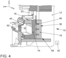
- Figure 4 shows a schematic view of a panel bender 10 with a crowning.
- the structure of the panel bender 10 shown in Figure 4 corresponds to the panel bender 10 shown in Figures 1 and 2 .
- Figures 1 and 2 To avoid repetition, not all details of Figures 1 and 2 are described in the following description of Figure 4 ; reference is made to these two figures.
- the machine body 12 of the panel bender 10 extends in a first direction z, which runs vertically, a second direction y, which runs horizontally, and a third direction x, which runs horizontally and perpendicular to the other two directions z and y.
- a bending line, along which sheet metal parts are bent by the panel bender 10, runs in the x direction.
- Bending is carried out by means of a bending beam 16, which is mounted on the machine body 12 so as to be movable in the z and y directions.
- the bending beam 16 is supported here on at least two drive guide units 18, which can be moved in the z direction on the machine body 12 and are each driven by a first drive 20.
- the drive guide units 18, of which more than two can be provided, are arranged along the x direction.
- the bending beam 16 is movably supported in the drive guide units 18, specifically in the y direction.
- the two movement axes in the z and y directions are technically separate movements and thus decoupled from one another, which simplifies both the construction and the control and also increases the accuracy.
- a second drive 36 with three drive elements 46 is arranged in the drive guide unit 18.
- the three drive elements 46 are arranged along the z direction and can be arranged in an axis or an extension of the axis of the first drive 20.
- the second drive 36 exerts an actuating force in the y direction.
- the drive elements 46 engage the bending beam in order to move the same and allow an almost flat introduction of force.
- Scaling the machines is significantly simplified according to the invention. If more bending force is required, for example in the case of larger machine lengths or the bending of thicker sheets, the number of second drives 36 or the short-stroke cylinders can be increased.
- Each of the three short-stroke cylinders shown here can be referred to as a second drive 36.
- the three short-stroke cylinders shown here can be referred to collectively as a second drive 36.
- the first drive(s) 20 move the drive guide units 18 in the vertical direction z.
- the second drives 36 are thus moved along with the drive guide units 18.
- the second drives 36 can be moved independently and decoupled from the first drives 20.
- the bending beam 16 is received and held in the drive guide units 18.
- An extension of the bending beam 16 in the direction of the y direction is smaller here than an extension of the bending beam 16 in the direction of the z direction. In this way, torques can be reduced by the x direction.
- Multiple drive guide units 18 are arranged along the x direction, wherein the bending beam 16 is arranged in the multiple drive guide units 18.
- Station operation can be enabled between two drive guide units 18, so that, for example, multiple work steps can be carried out along the bending line or in the x direction.
- At least one second drive 36 can form a crowning unit 48 to compensate for a deformation of the bending beam 16.
- the crowning unit 48 is connected to the bending beam 16 in the vertical y direction and thus moves with it. Positive and negative bends are thus crowned in the same way and allow a simplified control.
- a controller 42 of the panel bender 10 is used to control the at least one first drive 20 and the at least one second drive 36 and is only shown schematically here.
- the controller 42 is connected to the drives 20, 36, at least one sensor 46 and, if necessary, further controllers.
- the controller 42 is configured to align a bending tool 44 arranged on the bending beam 16 in the first and second directions along a bending line.
- Sensors 46 for measuring a deformation of the bending beam 16 during a bending process can provide measured values.
- manipulated variables for the first and/or the second drive 20, 36 to compensate for the deformation can be derived.
- the controller 42 can then control the drive(s) 20, 36 in accordance with the manipulated variables.
- the crowning takes place here by compensating for the deformation of the bending beam 16 during a bending process.
- the drive or the control for the crowning can be superimposed on a drive or a control for the movement of the bending beam 16.
- the drive elements 46 of a second drive 36 can be controlled in parallel or differently. If the drive elements 46 are, for example, short-stroke cylinders, the same or different pressures can be applied to them.
- the method for crowning a bending beam of a panel bender can run in the controller 42.
- a deformation of the bending beam 16 is measured during a bending process by means of at least one sensor 50. Deformations in all directions, preferably the y direction, can be recorded.
- a manipulated variable for the first and the second drive 20, 36 is then determined.
- separate manipulated variables can be determined for the second drive 36 for each drive element 46 of the second drive 36.
- a single manipulated variable can be determined for a second drive 36. It is possible, for example, that a single manipulated variable is determined for a second drive 36 for a movement of the bending beam 16 and that separate manipulated variables are determined for each drive element 46 of the second drive 36 for crowning.
- first and second drives are controlled separately. This separate activation can take place at the same time; the separation of activation relates to the functionality. Thus, a crowning only requires the control of the drive elements 46 or the second drives 36.
- the crowning or the crowning unit presented here is connected to the bending beam in the vertical direction and moves with the bending beam. Positive and negative bends are thus crowned in the same way and allow a simplified control.
Landscapes
- Engineering & Computer Science (AREA)
- Mechanical Engineering (AREA)
- Bending Of Plates, Rods, And Pipes (AREA)
Claims (12)
- Cintreuse de panneaux (10) pour le pliage de tôles au moyen d'au moins un outil de cintrage (44) agencé sur une poutre de cintrage (16), dans laquelle la poutre de cintrage (16) s'étend le long d'une direction (x),comportant un corps de machine (12),comportant au moins deux réceptacles de guidage (24) qui s'étendent dans une première direction (z) sur le corps de machine (12), dans laquelle la première direction (z) est perpendiculaire à la direction (x) le long de laquelle s'étend la poutre de cintrage (16), comportant au moins deux unités de guidage d'entraînement (18) qui sont agencées de manière mobile dans les au moins deux réceptacles de guidage (24) etdans laquelle la poutre de cintrage (16) est agencée de manière mobile dans les unités de guidage d'entraînement (18) dans une seconde direction (y) s'étendant perpendiculairement à la première direction (z) et perpendiculairement à la direction (x) le long de laquelle s'étend la poutre de cintrage (16),caractérisée en ce queau moins un second entraînement (36) est agencé dans chaque unité de guidage d'entraînement (18), dans laquelle le au moins un second entraînement (36) vient en prise avec la poutre de cintrage (16) pour déplacer celle-ci dans la seconde direction (y).
- Cintreuse de panneaux (10) selon la revendication 1, caractérisée en ce que la première direction (z) s'étend verticalement et en ce que la seconde direction (y) s'étend horizontalement.
- Cintreuse de panneaux (10) selon l'une quelconque des revendications précédentes, caractérisée en ce que l'unité de guidage d'entraînement (18) comporte un corps de base sensiblement en forme de C (28), dans laquelle un contour interne de l'unité de guidage d'entraînement (18) correspond au moins partiellement à un contour externe de la poutre de cintrage (16).
- Cintreuse de panneaux (10) selon la revendication 3, caractérisée en ce qu'un élément d'alimentation (40) est prévu en tant que palier de support pour la poutre de cintrage (16) dans l'unité de guidage d'entraînement (18), dans laquelle l'élément d'alimentation (40) peut être fixé au niveau d'une extrémité d'une branche inférieure (38) du corps de base en forme de C (28).
- Cintreuse de panneaux (10) selon l'une quelconque des revendications précédentes, caractérisée en ce qu'au moins un premier entraînement (20, 36) est prévu sur le corps de machine (12), dans laquelle l'au moins un premier entraînement (20) vient en prise avec au moins une unité de guidage d'entraînement (18) pour déplacer celle-ci.
- Cintreuse de panneaux (10) selon l'une quelconque des revendications précédentes, caractérisée en ce que les seconds entraînements (36) peuvent être actionnés indépendamment l'un de l'autre.
- Cintreuse de panneaux (10) selon les revendications 5 et 6, caractérisée en ce que le au moins un second entraînement (36) est agencé le long de la première direction (z) dans un axe du au moins un premier entraînement (20).
- Cintreuse de panneaux (10) selon la revendication 6 ou 7, caractérisée en ce que de multiples seconds entraînements (36) sont agencés le long de la première direction (z).
- Cintreuse de panneaux (10) selon l'une des revendications précédentes, caractérisée en ce que de multiples unités de guidage d'entraînement (18) sont agencées le long de la direction (x) le long de laquelle s'étend la poutre de cintrage et en ce que la poutre de cintrage (16) est agencée dans les multiples unités de guidage d'entraînement (18).
- Cintreuse de panneaux (10) selon la revendication 9, caractérisée en ce qu'un premier entraînement (20) est associé à chacune des multiples unités de guidage d'entraînement (18).
- Cintreuse de panneaux (10) selon l'une des revendications précédentes, caractérisée en ce qu'une extension de la poutre de cintrage (16) dans la direction de la seconde direction (y) est plus petite qu'une extension de la poutre de cintrage (16) dans la direction de la première direction (z).
- Cintreuse de panneaux (10) selon la revendication 5, caractérisée en ce qu'un dispositif de commande (42) est prévu pour commander le au moins un premier entraînement (20) et le au moins un second entraînement (36) et en ce que le dispositif de commande (42) est agencé pour aligner le au moins un outil de cintrage (44) agencé sur la poutre de cintrage (16) dans les première (z) et seconde (y) directions le long d'une ligne de cintrage.
Applications Claiming Priority (2)
| Application Number | Priority Date | Filing Date | Title |
|---|---|---|---|
| EP20196432.7A EP3970876A1 (fr) | 2020-09-16 | 2020-09-16 | Cintreuse de panneaux pour le pliage de tôles |
| PCT/EP2021/074616 WO2022058204A1 (fr) | 2020-09-16 | 2021-09-07 | Cintreuse de panneau pour cintrer de la tôle |
Publications (2)
| Publication Number | Publication Date |
|---|---|
| EP4164819A1 EP4164819A1 (fr) | 2023-04-19 |
| EP4164819B1 true EP4164819B1 (fr) | 2023-10-18 |
Family
ID=72521528
Family Applications (2)
| Application Number | Title | Priority Date | Filing Date |
|---|---|---|---|
| EP20196432.7A Withdrawn EP3970876A1 (fr) | 2020-09-16 | 2020-09-16 | Cintreuse de panneaux pour le pliage de tôles |
| EP21773377.3A Active EP4164819B1 (fr) | 2020-09-16 | 2021-09-07 | Cintreuse de panneaux pour le pliage de tôles |
Family Applications Before (1)
| Application Number | Title | Priority Date | Filing Date |
|---|---|---|---|
| EP20196432.7A Withdrawn EP3970876A1 (fr) | 2020-09-16 | 2020-09-16 | Cintreuse de panneaux pour le pliage de tôles |
Country Status (2)
| Country | Link |
|---|---|
| EP (2) | EP3970876A1 (fr) |
| WO (1) | WO2022058204A1 (fr) |
Family Cites Families (4)
| Publication number | Priority date | Publication date | Assignee | Title |
|---|---|---|---|---|
| AT372883B (de) | 1981-10-09 | 1983-11-25 | Voest Alpine Ag | Vorrichtung zum abkanten einer blechtafel |
| IT1292259B1 (it) * | 1997-04-15 | 1999-01-29 | Antonio Codatto | Pressa piegatrice per lamiere. |
| ITVR20110061A1 (it) * | 2011-03-30 | 2012-10-01 | Finn Power Italia S R L | Meccanismo di movimentazione per struttura portalame di macchina pannellatrice per l'esecuzione di piegature su fogli di lamiera metallica |
| ITUB20160836A1 (it) * | 2016-02-18 | 2017-08-18 | Olma S R L | Gruppo di piegatura di una macchina utensile pannellatrice |
-
2020
- 2020-09-16 EP EP20196432.7A patent/EP3970876A1/fr not_active Withdrawn
-
2021
- 2021-09-07 WO PCT/EP2021/074616 patent/WO2022058204A1/fr not_active Ceased
- 2021-09-07 EP EP21773377.3A patent/EP4164819B1/fr active Active
Also Published As
| Publication number | Publication date |
|---|---|
| EP4164819A1 (fr) | 2023-04-19 |
| EP3970876A1 (fr) | 2022-03-23 |
| WO2022058204A1 (fr) | 2022-03-24 |
Similar Documents
| Publication | Publication Date | Title |
|---|---|---|
| EP2614899B1 (fr) | Presse | |
| US8113032B2 (en) | Punch device | |
| JPH02247031A (ja) | 薄板部品の機械加工のためのいくつかのプレスを有するプレス設備 | |
| EP1484170A1 (fr) | Presse | |
| EP2352604B1 (fr) | Procede et dispositf de mesure d'un angle de pliage | |
| CN101633016A (zh) | 模具移动式龙门数控冲床 | |
| JP6659614B2 (ja) | プレスの2つのビーム間の変形加工中の偏差を補償するための方法および装置 | |
| US11325176B2 (en) | Multiple stroke slotting of planar workpieces | |
| CN112845779B (zh) | 一种组合式液压冲床及其冲压方法 | |
| CN105916606A (zh) | 压弯机 | |
| US20230330736A1 (en) | Readjustment device and readjustment method for a plate-like workpiece in a processing machine | |
| US11376647B2 (en) | Tools, machines, and methods for machining planar workpieces | |
| EP4164819B1 (fr) | Cintreuse de panneaux pour le pliage de tôles | |
| EP0550042B1 (fr) | Presse de précision pour plier des pièces en tôle relativement courtes | |
| KR20110000399A (ko) | 레이저 용접장치 | |
| US11471924B2 (en) | Tools, machines, and methods for processing planar workpieces | |
| JP7317843B2 (ja) | 工具交換ユニットとクランプジョウを有する製造設備及び工具交換方法 | |
| EP1243376B1 (fr) | Machine-outil d'usinage à grande vitesse avec bâti déplaçable | |
| KR101012817B1 (ko) | 하이브리드 드로잉 쿠션 장치 | |
| GB2562845B (en) | Blank holder device for a drawing device for producing hollow cylindrical bodies | |
| EP4166253B1 (fr) | Presse-plieuse | |
| JP3639201B2 (ja) | プレスブレーキ | |
| EP4000757B1 (fr) | Machine à travailler les tôles et similaires | |
| JP7853161B2 (ja) | 被加工材位置調整装置、被加工材位置調整方法、及び積層鉄心の製造方法 | |
| JP4444688B2 (ja) | 板金加工装置およびその装置を用いた折り曲げ加工方法 |
Legal Events
| Date | Code | Title | Description |
|---|---|---|---|
| STAA | Information on the status of an ep patent application or granted ep patent |
Free format text: STATUS: UNKNOWN |
|
| STAA | Information on the status of an ep patent application or granted ep patent |
Free format text: STATUS: THE INTERNATIONAL PUBLICATION HAS BEEN MADE |
|
| PUAI | Public reference made under article 153(3) epc to a published international application that has entered the european phase |
Free format text: ORIGINAL CODE: 0009012 |
|
| STAA | Information on the status of an ep patent application or granted ep patent |
Free format text: STATUS: REQUEST FOR EXAMINATION WAS MADE |
|
| 17P | Request for examination filed |
Effective date: 20230112 |
|
| AK | Designated contracting states |
Kind code of ref document: A1 Designated state(s): AL AT BE BG CH CY CZ DE DK EE ES FI FR GB GR HR HU IE IS IT LI LT LU LV MC MK MT NL NO PL PT RO RS SE SI SK SM TR |
|
| GRAP | Despatch of communication of intention to grant a patent |
Free format text: ORIGINAL CODE: EPIDOSNIGR1 |
|
| STAA | Information on the status of an ep patent application or granted ep patent |
Free format text: STATUS: GRANT OF PATENT IS INTENDED |
|
| DAV | Request for validation of the european patent (deleted) | ||
| DAX | Request for extension of the european patent (deleted) | ||
| INTG | Intention to grant announced |
Effective date: 20230622 |
|
| GRAS | Grant fee paid |
Free format text: ORIGINAL CODE: EPIDOSNIGR3 |
|
| GRAA | (expected) grant |
Free format text: ORIGINAL CODE: 0009210 |
|
| STAA | Information on the status of an ep patent application or granted ep patent |
Free format text: STATUS: THE PATENT HAS BEEN GRANTED |
|
| AK | Designated contracting states |
Kind code of ref document: B1 Designated state(s): AL AT BE BG CH CY CZ DE DK EE ES FI FR GB GR HR HU IE IS IT LI LT LU LV MC MK MT NL NO PL PT RO RS SE SI SK SM TR |
|
| REG | Reference to a national code |
Ref country code: GB Ref legal event code: FG4D |
|
| REG | Reference to a national code |
Ref country code: CH Ref legal event code: EP |
|
| P01 | Opt-out of the competence of the unified patent court (upc) registered |
Effective date: 20230925 |
|
| REG | Reference to a national code |
Ref country code: IE Ref legal event code: FG4D |
|
| REG | Reference to a national code |
Ref country code: DE Ref legal event code: R096 Ref document number: 602021006055 Country of ref document: DE |
|
| REG | Reference to a national code |
Ref country code: DE Ref legal event code: R082 Ref document number: 602021006055 Country of ref document: DE Representative=s name: KRAUS & LEDERER PARTGMBB, DE |
|
| REG | Reference to a national code |
Ref country code: LT Ref legal event code: MG9D |
|
| REG | Reference to a national code |
Ref country code: NL Ref legal event code: MP Effective date: 20231018 |
|
| REG | Reference to a national code |
Ref country code: AT Ref legal event code: MK05 Ref document number: 1621954 Country of ref document: AT Kind code of ref document: T Effective date: 20231018 |
|
| PG25 | Lapsed in a contracting state [announced via postgrant information from national office to epo] |
Ref country code: NL Free format text: LAPSE BECAUSE OF FAILURE TO SUBMIT A TRANSLATION OF THE DESCRIPTION OR TO PAY THE FEE WITHIN THE PRESCRIBED TIME-LIMIT Effective date: 20231018 |
|
| PG25 | Lapsed in a contracting state [announced via postgrant information from national office to epo] |
Ref country code: GR Free format text: LAPSE BECAUSE OF FAILURE TO SUBMIT A TRANSLATION OF THE DESCRIPTION OR TO PAY THE FEE WITHIN THE PRESCRIBED TIME-LIMIT Effective date: 20240119 |
|
| PG25 | Lapsed in a contracting state [announced via postgrant information from national office to epo] |
Ref country code: IS Free format text: LAPSE BECAUSE OF FAILURE TO SUBMIT A TRANSLATION OF THE DESCRIPTION OR TO PAY THE FEE WITHIN THE PRESCRIBED TIME-LIMIT Effective date: 20240218 |
|
| PG25 | Lapsed in a contracting state [announced via postgrant information from national office to epo] |
Ref country code: LT Free format text: LAPSE BECAUSE OF FAILURE TO SUBMIT A TRANSLATION OF THE DESCRIPTION OR TO PAY THE FEE WITHIN THE PRESCRIBED TIME-LIMIT Effective date: 20231018 |
|
| PG25 | Lapsed in a contracting state [announced via postgrant information from national office to epo] |
Ref country code: AT Free format text: LAPSE BECAUSE OF FAILURE TO SUBMIT A TRANSLATION OF THE DESCRIPTION OR TO PAY THE FEE WITHIN THE PRESCRIBED TIME-LIMIT Effective date: 20231018 |
|
| PG25 | Lapsed in a contracting state [announced via postgrant information from national office to epo] |
Ref country code: ES Free format text: LAPSE BECAUSE OF FAILURE TO SUBMIT A TRANSLATION OF THE DESCRIPTION OR TO PAY THE FEE WITHIN THE PRESCRIBED TIME-LIMIT Effective date: 20231018 |
|
| PG25 | Lapsed in a contracting state [announced via postgrant information from national office to epo] |
Ref country code: LT Free format text: LAPSE BECAUSE OF FAILURE TO SUBMIT A TRANSLATION OF THE DESCRIPTION OR TO PAY THE FEE WITHIN THE PRESCRIBED TIME-LIMIT Effective date: 20231018 Ref country code: IS Free format text: LAPSE BECAUSE OF FAILURE TO SUBMIT A TRANSLATION OF THE DESCRIPTION OR TO PAY THE FEE WITHIN THE PRESCRIBED TIME-LIMIT Effective date: 20240218 Ref country code: GR Free format text: LAPSE BECAUSE OF FAILURE TO SUBMIT A TRANSLATION OF THE DESCRIPTION OR TO PAY THE FEE WITHIN THE PRESCRIBED TIME-LIMIT Effective date: 20240119 Ref country code: ES Free format text: LAPSE BECAUSE OF FAILURE TO SUBMIT A TRANSLATION OF THE DESCRIPTION OR TO PAY THE FEE WITHIN THE PRESCRIBED TIME-LIMIT Effective date: 20231018 Ref country code: BG Free format text: LAPSE BECAUSE OF FAILURE TO SUBMIT A TRANSLATION OF THE DESCRIPTION OR TO PAY THE FEE WITHIN THE PRESCRIBED TIME-LIMIT Effective date: 20240118 Ref country code: AT Free format text: LAPSE BECAUSE OF FAILURE TO SUBMIT A TRANSLATION OF THE DESCRIPTION OR TO PAY THE FEE WITHIN THE PRESCRIBED TIME-LIMIT Effective date: 20231018 Ref country code: PT Free format text: LAPSE BECAUSE OF FAILURE TO SUBMIT A TRANSLATION OF THE DESCRIPTION OR TO PAY THE FEE WITHIN THE PRESCRIBED TIME-LIMIT Effective date: 20240219 |
|
| PG25 | Lapsed in a contracting state [announced via postgrant information from national office to epo] |
Ref country code: SE Free format text: LAPSE BECAUSE OF FAILURE TO SUBMIT A TRANSLATION OF THE DESCRIPTION OR TO PAY THE FEE WITHIN THE PRESCRIBED TIME-LIMIT Effective date: 20231018 Ref country code: RS Free format text: LAPSE BECAUSE OF FAILURE TO SUBMIT A TRANSLATION OF THE DESCRIPTION OR TO PAY THE FEE WITHIN THE PRESCRIBED TIME-LIMIT Effective date: 20231018 Ref country code: PL Free format text: LAPSE BECAUSE OF FAILURE TO SUBMIT A TRANSLATION OF THE DESCRIPTION OR TO PAY THE FEE WITHIN THE PRESCRIBED TIME-LIMIT Effective date: 20231018 Ref country code: NO Free format text: LAPSE BECAUSE OF FAILURE TO SUBMIT A TRANSLATION OF THE DESCRIPTION OR TO PAY THE FEE WITHIN THE PRESCRIBED TIME-LIMIT Effective date: 20240118 Ref country code: LV Free format text: LAPSE BECAUSE OF FAILURE TO SUBMIT A TRANSLATION OF THE DESCRIPTION OR TO PAY THE FEE WITHIN THE PRESCRIBED TIME-LIMIT Effective date: 20231018 Ref country code: HR Free format text: LAPSE BECAUSE OF FAILURE TO SUBMIT A TRANSLATION OF THE DESCRIPTION OR TO PAY THE FEE WITHIN THE PRESCRIBED TIME-LIMIT Effective date: 20231018 |
|
| PG25 | Lapsed in a contracting state [announced via postgrant information from national office to epo] |
Ref country code: DK Free format text: LAPSE BECAUSE OF FAILURE TO SUBMIT A TRANSLATION OF THE DESCRIPTION OR TO PAY THE FEE WITHIN THE PRESCRIBED TIME-LIMIT Effective date: 20231018 |
|
| REG | Reference to a national code |
Ref country code: DE Ref legal event code: R097 Ref document number: 602021006055 Country of ref document: DE |
|
| PG25 | Lapsed in a contracting state [announced via postgrant information from national office to epo] |
Ref country code: CZ Free format text: LAPSE BECAUSE OF FAILURE TO SUBMIT A TRANSLATION OF THE DESCRIPTION OR TO PAY THE FEE WITHIN THE PRESCRIBED TIME-LIMIT Effective date: 20231018 |
|
| PG25 | Lapsed in a contracting state [announced via postgrant information from national office to epo] |
Ref country code: SK Free format text: LAPSE BECAUSE OF FAILURE TO SUBMIT A TRANSLATION OF THE DESCRIPTION OR TO PAY THE FEE WITHIN THE PRESCRIBED TIME-LIMIT Effective date: 20231018 |
|
| PG25 | Lapsed in a contracting state [announced via postgrant information from national office to epo] |
Ref country code: SM Free format text: LAPSE BECAUSE OF FAILURE TO SUBMIT A TRANSLATION OF THE DESCRIPTION OR TO PAY THE FEE WITHIN THE PRESCRIBED TIME-LIMIT Effective date: 20231018 Ref country code: SK Free format text: LAPSE BECAUSE OF FAILURE TO SUBMIT A TRANSLATION OF THE DESCRIPTION OR TO PAY THE FEE WITHIN THE PRESCRIBED TIME-LIMIT Effective date: 20231018 Ref country code: RO Free format text: LAPSE BECAUSE OF FAILURE TO SUBMIT A TRANSLATION OF THE DESCRIPTION OR TO PAY THE FEE WITHIN THE PRESCRIBED TIME-LIMIT Effective date: 20231018 Ref country code: EE Free format text: LAPSE BECAUSE OF FAILURE TO SUBMIT A TRANSLATION OF THE DESCRIPTION OR TO PAY THE FEE WITHIN THE PRESCRIBED TIME-LIMIT Effective date: 20231018 Ref country code: DK Free format text: LAPSE BECAUSE OF FAILURE TO SUBMIT A TRANSLATION OF THE DESCRIPTION OR TO PAY THE FEE WITHIN THE PRESCRIBED TIME-LIMIT Effective date: 20231018 Ref country code: CZ Free format text: LAPSE BECAUSE OF FAILURE TO SUBMIT A TRANSLATION OF THE DESCRIPTION OR TO PAY THE FEE WITHIN THE PRESCRIBED TIME-LIMIT Effective date: 20231018 |
|
| PLBE | No opposition filed within time limit |
Free format text: ORIGINAL CODE: 0009261 |
|
| STAA | Information on the status of an ep patent application or granted ep patent |
Free format text: STATUS: NO OPPOSITION FILED WITHIN TIME LIMIT |
|
| 26N | No opposition filed |
Effective date: 20240719 |
|
| PGFP | Annual fee paid to national office [announced via postgrant information from national office to epo] |
Ref country code: FR Payment date: 20240808 Year of fee payment: 4 |
|
| PG25 | Lapsed in a contracting state [announced via postgrant information from national office to epo] |
Ref country code: SI Free format text: LAPSE BECAUSE OF FAILURE TO SUBMIT A TRANSLATION OF THE DESCRIPTION OR TO PAY THE FEE WITHIN THE PRESCRIBED TIME-LIMIT Effective date: 20231018 |
|
| PG25 | Lapsed in a contracting state [announced via postgrant information from national office to epo] |
Ref country code: SI Free format text: LAPSE BECAUSE OF FAILURE TO SUBMIT A TRANSLATION OF THE DESCRIPTION OR TO PAY THE FEE WITHIN THE PRESCRIBED TIME-LIMIT Effective date: 20231018 |
|
| PGFP | Annual fee paid to national office [announced via postgrant information from national office to epo] |
Ref country code: CH Payment date: 20241001 Year of fee payment: 4 |
|
| PG25 | Lapsed in a contracting state [announced via postgrant information from national office to epo] |
Ref country code: MC Free format text: LAPSE BECAUSE OF FAILURE TO SUBMIT A TRANSLATION OF THE DESCRIPTION OR TO PAY THE FEE WITHIN THE PRESCRIBED TIME-LIMIT Effective date: 20231018 |
|
| PG25 | Lapsed in a contracting state [announced via postgrant information from national office to epo] |
Ref country code: LU Free format text: LAPSE BECAUSE OF NON-PAYMENT OF DUE FEES Effective date: 20240907 |
|
| PG25 | Lapsed in a contracting state [announced via postgrant information from national office to epo] |
Ref country code: IE Free format text: LAPSE BECAUSE OF NON-PAYMENT OF DUE FEES Effective date: 20240907 |
|
| PG25 | Lapsed in a contracting state [announced via postgrant information from national office to epo] |
Ref country code: FI Free format text: LAPSE BECAUSE OF FAILURE TO SUBMIT A TRANSLATION OF THE DESCRIPTION OR TO PAY THE FEE WITHIN THE PRESCRIBED TIME-LIMIT Effective date: 20231019 |
|
| PGFP | Annual fee paid to national office [announced via postgrant information from national office to epo] |
Ref country code: DE Payment date: 20250805 Year of fee payment: 5 |
|
| PGFP | Annual fee paid to national office [announced via postgrant information from national office to epo] |
Ref country code: IT Payment date: 20250825 Year of fee payment: 5 |
|
| PGFP | Annual fee paid to national office [announced via postgrant information from national office to epo] |
Ref country code: BE Payment date: 20250818 Year of fee payment: 5 |
|
| PG25 | Lapsed in a contracting state [announced via postgrant information from national office to epo] |
Ref country code: CY Free format text: LAPSE BECAUSE OF FAILURE TO SUBMIT A TRANSLATION OF THE DESCRIPTION OR TO PAY THE FEE WITHIN THE PRESCRIBED TIME-LIMIT; INVALID AB INITIO Effective date: 20210907 |
|
| PG25 | Lapsed in a contracting state [announced via postgrant information from national office to epo] |
Ref country code: HU Free format text: LAPSE BECAUSE OF FAILURE TO SUBMIT A TRANSLATION OF THE DESCRIPTION OR TO PAY THE FEE WITHIN THE PRESCRIBED TIME-LIMIT; INVALID AB INITIO Effective date: 20210907 |