EP4165633B1 - Procédés, appareil et systèmes pour la détection et l'extraction de sources sonores de sous-bande identifiables spatialement - Google Patents
Procédés, appareil et systèmes pour la détection et l'extraction de sources sonores de sous-bande identifiables spatialement Download PDFInfo
- Publication number
- EP4165633B1 EP4165633B1 EP21735560.1A EP21735560A EP4165633B1 EP 4165633 B1 EP4165633 B1 EP 4165633B1 EP 21735560 A EP21735560 A EP 21735560A EP 4165633 B1 EP4165633 B1 EP 4165633B1
- Authority
- EP
- European Patent Office
- Prior art keywords
- phase difference
- parameters
- panning
- parameter
- frequency
- Prior art date
- Legal status (The legal status is an assumption and is not a legal conclusion. Google has not performed a legal analysis and makes no representation as to the accuracy of the status listed.)
- Active
Links
Images


Classifications
-
- G—PHYSICS
- G10—MUSICAL INSTRUMENTS; ACOUSTICS
- G10L—SPEECH ANALYSIS TECHNIQUES OR SPEECH SYNTHESIS; SPEECH RECOGNITION; SPEECH OR VOICE PROCESSING TECHNIQUES; SPEECH OR AUDIO CODING OR DECODING
- G10L21/00—Speech or voice signal processing techniques to produce another audible or non-audible signal, e.g. visual or tactile, in order to modify its quality or its intelligibility
- G10L21/02—Speech enhancement, e.g. noise reduction or echo cancellation
- G10L21/0272—Voice signal separating
Definitions
- This disclosure relates generally to audio signal processing, and in particular to audio source separation techniques.
- Two-channel audio mixes are created by mixing multiple audio sources together.
- it is desirable to detect and extract the individual audio sources from two-channel mixes including but not limited to: remixing applications, where the audio sources are relocated in the two-channel mix, upmixing applications, where the audio sources are located or relocated in a surround sound mix, and audio source enhancement applications, where certain audio sources (e.g., speech/dialog) are boosted and added back to the two-channel or a surround sound mix.
- remixing applications where the audio sources are relocated in the two-channel mix
- upmixing applications where the audio sources are located or relocated in a surround sound mix
- audio source enhancement applications where certain audio sources (e.g., speech/dialog) are boosted and added back to the two-channel or a surround sound mix.
- a method comprises: transforming, using one or more processors, one or more frames of a two-channel time domain audio signal into a time-frequency domain representation including a plurality of time-frequency tiles, wherein the frequency domain of the time-frequency domain representation includes a plurality of frequency bins grouped into a plurality of subbands; for each time-frequency tile: calculating, using the one or more processors, spatial parameters and a level for the time-frequency tile; modifying, using the one or more processors, the spatial parameters using shift and squeeze parameters; obtaining, using the one or more processors, a softmask value for each frequency bin using the modified spatial parameters, the level and subband information; and applying, using the one or more processors, the softmask values to the time-frequency tile to generate a modified time-frequency tile of an estimated audio source.
- a plurality of frames of the time-frequency tiles are assembled into a plurality of chunks, each chunk including a plurality of subbands
- the method comprises: for each subband in each chunk: calculating, using the one or more processors, spatial parameters and a level for each time-frequency tile in the chunk; modifying, using the one or more processors, the spatial parameters using shift and squeeze parameters; obtaining, using the one or more processors, a softmask value for each frequency bin using the modified spatial parameters, the level and subband information; and applying, using the one or more processors, the softmask values to the time-frequency tile to generate a modified time-frequency tile of the estimated audio source.
- the method further comprises transforming, using the one or more processors, the modified time-frequency tiles into a plurality of time domain audio source signals.
- the spatial parameters include panning and phase difference for each of the time-frequency tiles.
- the method comprises, for each subband, determining a statistical distribution of the panning parameters and a statistical distribution of the phase difference parameters; determining the shift parameters as the panning parameter and the phase difference parameter corresponding to a peak value of the respective statistical distributions of the panning parameters and phase difference parameters; and determining the squeeze parameters as a width around the peak value of the respective distributions of the panning parameters and phase difference parameters for capturing a predetermined amount of audio energy.
- the predetermined amount of audio energy is at least forty percent of the total energy in the statistical distribution of the panning parameters and at least eighty percent of the total energy in statistical distribution of the phase difference parameters.
- the softmask values are obtained from a lookup table or function for a spatio-level filtering (SLF) system trained for a center-panned target source.
- SPF spatio-level filtering
- transforming one or more frames of a two-channel time domain audio signal into a frequency domain signal comprises applying a short-time frequency transform (STFT) to the two-channel time domain audio signal.
- STFT short-time frequency transform
- multiple frequency bins are grouped into octave subbands or approximately octave subbands.
- the spatial parameters include panning and phase difference parameters for each of the time-frequency tiles
- calculating shift and squeeze parameters further comprises: optionally assembling consecutive frames of the time-frequency tiles into chunks, each chunk including a plurality of subbands; for each subband in each chunk: creating a smoothed level-parameter-weighted histogram on the panning parameter; creating a smoothed, level-parameter-weighted first phase difference histogram on the first phase difference parameter, wherein the first phase difference parameter has a first range; creating a smoothed, level-parameter-weighted second phase difference histogram on the second phase difference parameter, wherein the second phase difference parameter has a second range that is different than the first range; detecting a panning peak in the smoothed panning histogram; determining a panning peak width; determining a panning middle value; detecting a first phase difference peak in the smoothed, first phase difference histogram; determining a first phase difference peak width; determining a first phase difference peak width;
- the statistical distribution of the panning parameters of the embodiment mentioned above may comprise the smoothed level-parameter-weighted histogram on the panning parameter.
- Determining the phase difference parameter corresponding to the peak value of the statistical distribution of the phase difference parameters and the width around the peak value of the statistical distribution of the phase difference parameters may comprises detecting the first and second phase difference peaks, determining the first and second phase difference peak widths, determining the first and second phase difference middle values.
- the method further comprises determining which of the first and second phase difference peak widths is more narrow (after adjustment), wherein the shift parameters include the panning middle value and the first or second phase difference middle value of the more narrow peak, and the squeeze parameters include the panning peak width and the first or second phase difference peak width that is more narrow.
- the shift parameters include the panning middle value and the first or second phase difference middle value of the more narrow peak
- the squeeze parameters include the panning peak width and the first or second phase difference peak width that is more narrow.
- the spatial parameters include panning and phase difference parameters for each of the time-frequency tiles, and calculating shift and squeeze parameters, further comprises: for each subband in each chunk: creating a smoothed level-parameter-weighted histogram on the panning parameter; creating a smoothed, level-parameter-weighted first phase difference histogram on the first phase difference parameter, wherein the first phase difference parameter has a first range; creating a smoothed, level-parameter-weighted second phase difference histogram on the second phase difference parameter, wherein the second phase difference parameter has a second range that is different than the first range; detecting a panning peak in the smoothed panning histogram; determining a panning peak width; determining a panning middle value; detecting a first phase difference peak in the smoothed, first phase difference histogram; determining a first phase difference peak width; determining a first phase difference middle value; detecting a second phase difference peak in the smoothed, second phase difference histogram; determining
- the method further comprises determining which of the first and second phase difference peak widths is more narrow (after adjustment), wherein the shift parameters include the panning middle value and the first or second phase difference middle value of the more narrow peak, and the squeeze parameters include the panning peak width and the first or second phase difference peak width that is more narrow.
- the first phase difference range is from - ⁇ to ⁇ radians
- the second phase difference range is from 0 to 2 ⁇ radians.
- the panning histogram and the first and second phase histograms are smoothed over time using panning and phase difference histograms created for previous and subsequent chunks, or weighted data in the previous and subsequent chunks is collected then directly used to form the histograms.
- the panning peak width captures at least forty percent of the total energy in the panning histogram, and the first and second phase difference peak widths each capture at least eighty percent of the total energy in their respective histograms.
- the shift and squeeze parameters for each subband in each chunk are converted to exist for each frame of the one or more frames.
- the panning shift and squeeze parameters are converted to exist for each frame using linear interpolation and the first or second phase difference shift parameter is converted to exist for each frame using a zero order hold.
- the method further comprises determining a single panning middle value and a single panning peak width value per unit of time for the one or more subbands in the one or more chunks.
- the softmask values are smoothed over time and frequency.
- an apparatus comprises: one or more processors and memory storing instructions that when executed by the one or more processors, cause the one or more processors to perform any of the preceding methods.
- a non-transitory, computer readable storage medium has stored thereon instructions, that when executed by one or more processors, cause the one or more processors to perform any of the preceding methods.
- spatially-identifiable subband audio sources are efficiently and robustly extracted from a two-channel mix.
- the system is robust because it can extract any spatially-identifiable subband audio source, including audio sources that are amplitude-panned and audio sources that are not amplitude-panned, such as audio sources that are mixed or recorded with delay between the channels, audio sources mixed or recorded with reverberation and audio sources with spatial characteristics that vary from frequency subband to frequency subband.
- the system is also efficient, requiring almost no training data or latency.
- each block in the flowcharts or block may represent a module, a program, or a part of code, which contains one or more executable instructions for performing specified logic functions.
- these blocks are illustrated in particular sequences for performing the steps of the methods, they may not necessarily be performed strictly in accordance with the illustrated sequence. For example, they might be performed in reverse sequence or simultaneously, depending on the nature of the respective operations.
- block diagrams and/or each block in the flowcharts and a combination of thereof may be implemented by a dedicated software-based or hardware-based system for performing specified functions/operations or by a combination of dedicated hardware and computer instructions.
- spatially-identifiable subband audio sources are subband audio sources that have their energy concentrated in space within octave frequency subbands or approximately octave frequency subbands.
- the disclosed embodiments are used primarily in the context of sound source separation systems which take two channel (stereo) signals as input, and operate in the frequency domain, such as the short-time Fourier transform (STFT) domain. There are four basic steps used in typical sound source separation systems.
- STFT short-time Fourier transform
- a front end is applied that transforms the two-channel time domain audio signal into a frequency domain.
- the STFT is commonly used which produces a spectrogram (e.g., magnitude and phase) of the input signal in the frequency domain.
- Elements of the STFT output may be referred to by indicating their indices in time and frequency; each such element may be called a time-frequency tile.
- Each time point corresponds to a frame number, which includes a plurality of frequency bins, which may be subdivided or grouped into subbands.
- the STFT parameters e.g., window type, hop size
- the described system calculates spatial parameters theta ( ⁇ ) and phi ( ⁇ ), and a level parameter U (all defined below) and makes note of the relevant quasi-octave subband b.
- the spatial parameters theta ( ⁇ ) and phi ( ⁇ ), and a level parameter U are used to perform extraction of estimated audio source(s) by applying a magnitude softmask (e.g., values in the continuous range [0,1]) to each bin of the STFT representation for each channel (e.g., each bin of each time-frequency tile for left and right channels).
- a magnitude softmask e.g., values in the continuous range [0,1]
- the STFT domain estimate of audio source(s) is converted to a two channel time domain estimate by performing an Inverse Short Term Fourier transform (ISTFT) on each channel's STFT representation. Note that while this step is described as "fourth" in sequence in this context, there may be other optional processing that occurs in the STFT domain before this fourth step. In an embodiment, the ISTFT is performed after other STFT domain processing is complete.
- ISTFT Inverse Short Term Fourier transform
- the parameters for each bin in the STFT representation include the two spatial parameters theta ( ⁇ ) and phi ( ⁇ ) and the parameter U, which are defined and calculated as follows.
- ⁇ ranges from +/- ⁇ , which are at opposite ends of the ⁇ range as defined here. Therefore, ⁇ 2 is defined which is the identical data as in ⁇ , but rotated on the unit circle such that the range is from 0 to 2 ⁇ . Mathematically, this just means that any values below 0 are set to their previous value plus 2 ⁇ . Note that ⁇ 2 is useful in specific parts of the system.
- the version of U in Equation [3] is on a dB scale and may also be called U dB.
- level-weighted-histograms This is specifically relevant to all references herein to "level-weighted-histograms.” It shall be understood that such references imply that various powers may be used when applying level-weighting; powers between 1 and 2 are recommended, and U-power (power of 2) is recommended in specific steps as noted.
- Each frequency bin ⁇ is understood to represent a particular frequency. However, data may also be grouped within subbands, which are collections of consecutive bins, where each frequency bin ⁇ belongs to a subband. Grouping data within subbands is particularly useful for certain estimation tasks performed in the system. In an embodiment, octave subbands or approximately octave subbands are used, though other subband definitions may be used. Some examples of banding include defining band edges as follows, where values are listed in Hz:
- the lowest band is selected to be equal in size to the second band, though other conventions may be used in other embodiments.
- the system processes groups of consecutive frames hereinafter also referred to as "chunks.” This allows data from multiple frames to be used for more stable estimates of spatial attributes. By using chunks, rather than just longer frame lengths, the advantages (e.g., quasistationarity, optimality for source separation) of specific frame lengths (e.g., between 50-100ms) are retained. Chunks may be overlapped by choosing a chunk hop size lower than the number of frames in the chunk. In an embodiment, the system uses chunks of 10 frames, with a chunk hop size of 5 frames.
- the chunks will require about 277 milliseconds of data.
- smaller or larger chunks or hop sizes could be used, with the amount of lookahead and lookback used also determined by the needs of the implementation. In an embodiment, there are 5 frames of lookahead and 5 frames of lookback for a chunk.
- the robust, efficient sound source separation system described herein uses a spatio-level filtering (SLF) system.
- SPF spatio-level filtering
- a Spatio-Level Filter (SLF) is a system that has been trained to extract a target source with a given level distribution and specified spatial parameters, from a mix which includes backgrounds with a given level distribution and spatial parameters.
- the target spatial parameters consist only of the panning parameter ⁇ 1, and further assume that ⁇ 1 corresponds to a center panned source.
- the techniques described herein could also be used in conjunction with an SLF trained to extract a target source whose spatial parameters are not so constrained; such a technique is described below in the context of shift and squeeze parameters.
- the panning parameter ⁇ 1 exists in the context of a signal model in which the target source, s1, and backgrounds, b, are mixed into two channels, hereinafter referred to as "left channel” (x1 or XL) and “right channel” (x2 or XR) depending on the context.
- STFT Short Time Fourier Transform
- the "target source” is assumed to be panned meaning it can be characterized by ⁇ 1. It should be clear by inspection that if a signal contains only the target source at a given point in time-frequency space, then the detected panning parameter theta ( ⁇ ) described above will yield a perfect estimate of the target source panning parameter ⁇ 1.
- ⁇ ( ⁇ , t ) , ⁇ ( ⁇ , t ) and U( ⁇ , t ) above which may also be notated ( ⁇ , ⁇ ,U) and understood to exist for each time-frequency tile ( ⁇ , t ) .
- Theta ( ⁇ ) and phi ( ⁇ ) are the "spatial parameters" detected, and U is the "level parameter” detected.
- the frequency value ⁇ for the tile in question is a member of a roughly-octave subband b, for which the SLF is trained.
- the SLF takes an input of the four values (b, ⁇ , ⁇ ,U) and outputs a single STFT softmask value.
- the STFT softmask value is thus determined by any trained SLF which takes four inputs and produces one output, for each time-frequency tile.
- the softmask value is multiplied by the input mix representation value to produce an estimated target source value.
- the SLF which takes in four inputs values and produces one output value, can exist in the form of a function (four inputs, one output) or table (four dimensional, with the values stored in the table representing the output values).
- the SLF used takes the form of a table.
- Table lookup 106 is a technique used to access values in a table using any approach familiar to those skilled in the art.
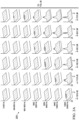
- FIG. 2 A visual depiction of the inputs and outputs of a typical trained SLF look-up table is shown in FIG. 2 .
- This non limiting, exemplary SLF system illustrated by FIG. 2 is one example SLF system that can be used in the disclosed embodiments
- Other SLF systems could also be used that: 1) are trained to extract a center-panned source; 2) have at least four inputs which include: ⁇ , ⁇ , U, and subband b, as defined above; 3) have at least one output which is a floating point value from 0 to 1 inclusive; 4) perform input/output operations for each STFT bin; 5) have a STFT-sized output consisting of a floating point value (referred to as a softmask) for each STFT tile; and 6) have an input STFT representation that is multiplied by the softmask value to obtain an estimated source output STFT representation, which is then transformed into a two-channel, time domain estimated source signal.
- a softmask a floating point value
- the spatial ⁇ and ⁇ parameters detected for the training data will have a distribution in each subband. These values give some notion of the "spread” or "width” of such data when there is a center panned source.
- a histogram analysis of the data in each subband is performed, which tracks the width to capture 40% of the energy versus ⁇ or 80% of the data versus ⁇ . These widths are recorded, respectively, as the "reference thetaWidth” and “reference phiWidth” for each subband.
- the reference ⁇ widths are [0.1 0.07 0.04 0.10 0.12 0.2 0.12] and the reference ⁇ widths are [0.6 0.5 0.4 0.6 0.8 1.0 1.0].
- a SLF look-up table is created by obtaining a first set of samples from a plurality of target source level and spatial distributions in frequency subbands in a frequency domain, obtaining a second set of samples from a plurality of background level and spatial distributions in frequency subbands in a frequency domain, adding the first and second sets of samples to create a combined set of samples, detecting level and spatial parameters for each sample in the combined set of samples for each subband, within subbands, weighting the detected level and spatial parameters by their respective level and spatial distributions for the target source and backgrounds; storing the weighted level, spatial parameters and signal-to-noise ratio (SNR) within subbands for each sample in the combined set of samples in a table; and re-indexing the table by the weighted level and spatial parameters and subband, such that the table includes a target percentile SNR of the weighted level and spatial parameters and subband, and that for a given input of quantized detected spatial and level parameters and subband, an estimated SNR associated with
- the exemplary audio source separation system described herein was designed based on investigations into examples of typical mixing of audio sources, including dialog. The system exploits the information found during the investigations. This next section briefly summarizes the results of the investigations, relevant assumptions, and relevant system objectives.
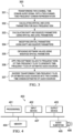
- FIG. 1 is a block diagram of an exemplary system 100 for detection and extraction of spatially-identifiable subband audio sources from two-channel mixes, in accordance with an embodiment.
- System 100 includes transform module 101, parameter extraction module 102, detection module 103, parameter modification module 104, table lookup module 105, look-up table 106, softmask application module 107 and inverse transform module 108.
- Each of these modules can be implemented in hardware or software or a combination of hardware or software.
- system 100 can be implemented by the device architecture shown in reference to FIG. 4 .
- Each module will now be described in turn with reference to FIG. 1 .
- transform module 101 transforms a two-channel time domain mixed audio signal (e.g., a stereo signal) into a frequency domain representation, such as an STFT domain representation (e.g., a spectrogram/time-frequency tile), using windows and parameters familiar to those skilled in the art.
- the window is a 4096 point square-root of a Hann window hopped at 1024 frames and the STFT is a 4096 point FFT for 48 kHz sampled input.
- Other windows can also be used, such as a Gaussian window.
- scaling that preserves hop size and frame length in milliseconds can be used for lower or higher sample rates.
- Extraction module 102 calculates the parameters ( ⁇ , ⁇ , U) described above for each time-frequency tile (bin and frame) in the STFT representation. That is, if an example has 1000 frames and uses 2049 unique STFT bins (assuming a 4096 point STFT) then there would be 2,049,000 values for each of the parameters( ⁇ , ⁇ , U).
- the U parameter is adjusted based on a measured input data level.
- a buffer of data is assembled for the current and some reasonable number of previous frames. This is intended to be a long term measurement. For practical purposes the buffer length will typically be multiple seconds (e.g., 5 seconds).
- the level is calculated for the frame using the loudness, k-weighted, relative to full scale (LKFS) method. Other methods could also be used. However, whichever method is used it should match the method used to calculate the level of the training data. Note that a similar but longer-term measurement is assumed to have been previously performed on the training data to yield the measured training data level.
- the measured input data level is the value in dB of the level (such as in LKFS) of the input data, which is measured in real time per frame as described above.
- the extra level shift is an optional user-selectable value. This value is used in a subsequent part of system 100 described below but is addressed here. By selecting a positive value, a user may specify that the input data is at a higher level than it actually is, which drives the system to use more selective values of the SLF system. The system operator may select this parameter via an interface, examples of which include parameter choice in an API call or editing the text of a configuration file.
- FIG. 2 which is a sampled representation of the inputs and outputs of an SLF system, provides an example of a relevant SLF system, although any SLF system may be utilized.
- the diagram in FIG. 2 is a 4-dimensional diagram.
- the four input variables are represented by the left-right and in-out axes of each subplot and the vertical and horizontal subplot indices. Respectively, these correspond to the input variables (1) modified theta (2) modified phi (3) subband b (4) level U.
- the horizontal subplot dimensions does not depict all levels stored in the SLF look-up table; doing so would require 128 left-right subplots as 1 dB increments are used over a range of 128dB in the table. In practice, finer or coarser increments could be used for higher accuracy or more lookup efficiency, respectively.
- the output variable is represented by the vertical value of each subplot; this corresponds to a softmask value between 0 and 1.
- Detection module 103 detects one spatially-identifiable audio source for each subband.
- the recommended method to do so involves histograms and is described in detail below.
- any method e.g. distribution estimation from Parzen windows, which (1) estimates the peak value of the relevant distributions on theta and phi, (2) estimates the range of said distributions to capture significant energy, e.g. a predetermined amount of audio energy, vs theta and phi (recommended 40% for theta and 80% for phi), meets the design requirements for the system. Note that for dialog audio sources, which have little energy above 13 kHz, the cost of detection for the top octave may not justify its use.
- Detection module 103 assembles consecutive frame data into chunks (e.g. 10-frame chunks). For each subband in each chunk (if in the first subband, data below 175 Hz is excluded as suggested above), detection module 103 creates a U-power weighted histogram on ⁇ that is smoothed over ⁇ . Also, the same process is applied to ⁇ (which ranges from - ⁇ to ⁇ ) and ⁇ 2 (which ranges from 0 to 2 ⁇ ) .
- the U-power weighted histograms may use any number of bins (e.g., 51 bins versus ⁇ , 102 bins versus ⁇ ).
- lower subbands have fewer data points, they will require more smoothing.
- fewer histogram bins may be used for lower subbands and more histogram bins may be used for higher subbands.
- Smoothing may be performed using techniques familiar to those experienced in the art. However, it is recommended, in a preferred embodiment, to smooth kernels are used over each of ⁇ and ⁇ that correspond to the following fractional values of the range of ⁇ or ⁇ data: 41%, 41%, 37%, 29%, 22%, 18% and 18%. Note that these 7 fractional values correspond to the 7 frequency subbands b, as shown in FIG. 2 .
- a smoothing technique that preserves peaks at the ends of a histogram can be used.
- the ⁇ histogram for a given chunk shall be influenced by the ⁇ histogram for the chunks before and or after it. Similar shall be true for histograms on ⁇ and ⁇ 2.
- the weightings recommended are as follows: current chunk 1.0, previous chunk 0.4, chunk before the previous chunk 0.2, future chunk 0.1.
- the method of smoothing may be either (1) share weighted data across time then create histograms from the smoothed data, or (2) first create histograms then share weighted histograms across time thereby smoothing the histograms. When memory and computation are limited, method (2) can be used.
- detection module 103 picks and detects peak width as follows. For the ⁇ histogram, detect the ⁇ value of the peak, referred to as “thetaMiddle,” and also the width around this peak necessary to capture 40% of energy in the histogram, referred to as "thetaWidth". The same process is applied for ⁇ and ⁇ 2, recording phiMiddle, phi2Middle, phiWidth and phi2Width, but when recording the width require 80% energy capture rather than 40%. Recall that ⁇ theta ranges from 0 (far left) to ⁇ /2 (far right) so the largest thetaWidth value will always be less than ⁇ /2.
- the widths for ⁇ and ⁇ 2 are known, the final values are recorded for phiMiddle and phiWidth based on which parameter had a higher concentration in ⁇ space as indicated by a smaller phiWidth value.
- ⁇ 2 is chosen only if the width is at least 2x smaller than that for ⁇ . This allows the rapid alternation between ⁇ and ⁇ 2 to be reduced when there is very widely distributed quasi-random data versus ⁇ .
- the thetaMiddle, thetaWidth, phiMiddle and phiWidth parameters are now know for each subband and chunk. (Recall that subbands and bins are different: there are only about 7 subbands, but likely 2049 unique bins. Frames and chunks are also different; there are multiple frames in each chunk.).
- the thetaMiddle, thetaWidth and phiWidth parameters are converted to exist per frame by using first order linear interpolation, though other techniques familiar to those skilled in the art may also be used.
- the phiMiddle parameter is converted to exist per frame by using a zeroth order hold, to avoid rapid phase change for cases where some chunks are close or equal to + ⁇ and some chunks are close or equal to - ⁇ .
- the parameters thetaMiddle and thetaWidth are hereinafter also referred to as “theta shift and squeeze” parameters, and the parameters phiMiddle and phiWidth are hereinafter also referred to as the "phi shift and squeeze” parameters.
- the four parameters are hereinafter referred to as "shift and squeeze” or "S&S" parameters.
- the S&S parameters can be conceptually understood to represent the difference between the detected concentrations of ⁇ and ⁇ data, and what the concentrations would have been for an ideal center-panned source with limited or no backgrounds. This concept will later allow the system to use the S&S parameters to modify the detected ( ⁇ , ⁇ , U) data in a way that an SLF designed for a center-panned source can be used to extract a target source with arbitrary concentration in ⁇ and ⁇ . Such application shall be understood to be the most optimal and recommended in most cases.
- the SLF used need not be trained only for a center-panned source, the S&S parameters need not be calculated relative to only a center-panned source, and the system need not limit itself to using only a single trained SLF model to perform target source extraction.
- arbitrary SLF models including a greater number of models, may be used. It is for efficiency that the system uses a single, center-panned source SLF.
- the above steps produce values corresponding to "middle” and "width” for each of ⁇ and ⁇ within each subband.
- a weighted sum of most of the subband ⁇ histograms is computed for a given chunk before peak picking, as follows. Due to spatially ambiguous special effects at low frequencies, which may challenge detection of speech sources in particular, subband 1 is optionally ignored entirely.
- Subband 2 is down weighted by scaling the subband 2 histograms by a factor (e.g., 0.1).
- the other subband histograms are weighted equally (e.g., by scaling by 1.0 each). Note that while higher octave subbands tend to have lower energy per bin, they have more bins which offsets this effect and ensures all subbands have a perceptually relevant chance to contribute to the single ⁇ estimate.
- the histogram is smoothed versus other time chunks as described above for thetaMiddle, etc.
- simple peak picking is performed. The peaks picked are the single ⁇ values per chunk. In an embodiment, linear interpolation is applied between chunks to obtain these values per frame. The single ⁇ value per frame obtained this way is hereinafter also called "singleTheta.”
- parameter modification module 104 uses the shift and squeeze (S&S) parameters to modify the parameters ( ⁇ , ⁇ ) values input to the SLF system.
- S&S shift and squeeze
- the steps for this part are as follows. Process frame by frame and subband by subband. That is, the below steps assume processing within a frame and subband. As before, any subband whose frequencies are mostly or entirely outside the range considered (e.g. above 13 kHz) may optionally be skipped; of course they should be skipped if the corresponding subband was skipped for S&S parameter detection because they will have no data to act on. If not otherwise specified, data described in variables herein is specific to the frame and subband considered. For example "thetaMiddle" is understood to have values for each frame and subband, so a reference to thetaMiddle implies consideration of the current frame and subband.
- the ⁇ values are modified according to their S&S parameters as follows.
- squeezeFactor thetaWidth/(reference thetaWidth value corresponding to the trained SLF to be applied). If the squeezeFactor is outside the range [1.0, 1.5] it is brought back within this range. Note that higher values than 1.5 may be used to allow more diffuse sources to be more fully captured. A squeezeFactor with value of 1.5 provides a good balance for extracting spatially identifiable sources. To make the system more selective, the reference thetaWidth (and reference phiWidth) values can be scaled down by multiplying them by 0.5 or other suitable factor.
- shiftFactor thetaMiddle(for this frame and subband) - ⁇ /4.
- ⁇ /4 is used here because it represents a center-panned source.
- the trained SLF system to be used shall be for a center-panned source.
- the squeezeFactor value should be limited as much as for theta above.
- an additional reality is accounted for.
- Sources with "extreme" ⁇ values near 0 (far left) or ⁇ /2 (far right) by definition are expected to always have wide distributions on phi. Therefore, it is not optimal to apply strict limits to "squeezing" in the phi dimension when thetaMiddle takes on extreme values.
- phiModified buff2/squeezeFactor is calculated. There should be no values outside the range - ⁇ to ⁇ at this point.
- table look-up module 105 retrieves softmask values from SLF look-up table 106 and softmask application module 107 applies the softmask values to STFT time-frequency tiles.
- the input values thetaModified, phiModified, and U are used to obtain a softmask value from look-up table 106, for each frame and bin.
- look-up table 106 is provided as an example embodiment, the SLF itself may be implemented using a variety of means, including but not limited to a look-up table, function, nested table and/or function, neural network(s), etc., in which there are four input values and one output value.
- n SLF n SLF
- the output is shown on the vertical axis of each subplot.
- the four input variables are the left-right ( ⁇ ) and in-out ( ⁇ ) axes of each subplot, as well as the vertical (subband b) and horizontal (level U) subplot indices.
- the output variable is between 0 and 1 inclusive and represents the fraction of the corresponding input STFT that shall be passed to the output. Since there is one (four dimensional) input per STFT tile, there is also one output per STFT tile.
- the result of applying the SLF function is an STFT-sized representation consisting of values between 0 and 1, also known as a softmask. This softmask representation is called "sourceMask1.”
- the softmask values and or signal values are smoothed over time and frequency using techniques familiar to those skilled in the art. Assuming a 4096 point FFT, a smoothing versus frequency can be used that uses the smoother [0.17 0.33 1.0 0.33 0.17]/sum([0.17 0.33 1.0 0.33 0.17]). For higher or lower FFT sizes some reasonable scaling of the smoothing range and coefficients should be performed. Assuming 1024 sample hop size, a smoother versus time of approximately [0.1 0.55 1.0 0.55 0.1]/sum([0.1 0.55 1.0 0.55 0.1]) can be used If hops size or frame length is changed, the smoothing should be appropriately adjusted.
- inverse transform module 108 performs an inverse STFT performed on the STFT representation of estimated audio sources.
- the same synthesis window (postwindow) as the analysis window is used to perform the inverse STFT, such as the square-root of a Hann window. Because there are two STFT representations, there are now two time-domain signals.
- the output of inverse transform module 108 is a two-channel time domain audio signal that combines the audio source(s) extracted from the six (or seven) of seven subbands. In some examples, this is all that is required, and the single time domain signal may be subsequently processed or exploited. In other examples, it may be desired to have each subband signal separately. This is especially relevant when the subband signals may have very different theta and or phi values from one another. For example, if subbands 1-4 have a far-left theta source, while subbands 5 and 6 have a center right source, the system can be configured to produce bandpass outputs, either by processing in the STFT domain before inverse transform module 108, or by bandpass filtering the estimated extracted audio source signals.
- FIG. 2 is a visual depiction of the inputs and outputs of an SLF system trained to extract panned sources, in accordance with an embodiment. More particularly, FIG. 2 is an example of the trained SLF look-up table described in FIG. 1 .
- Process 300 continues by calculating spatial and level parameters for each time-frequency tile (302). For example, process 300 calculates the ⁇ , ⁇ and U parameters for each time-frequency tile, as described in reference to FIG. 1 .
- Process 300 continues by obtaining softmask values using the modified spatial parameters ( ⁇ , ⁇ ) (305).
- the modified spatial parameters ( ⁇ , ⁇ ) can be used to select softmask values from a trained SLF lookup table, such as the example SLF look-up table shown in FIG. 2 .
- Process 300 continues by applying the softmask values to the time-frequency tiles to generate time-frequency tiles of estimated audio sources (306).
- the softmask values are continuous values between 0 and 1 (fractions) that are multiplied with their dimensionally corresponding magnitudes in the bins of the STFT tiles. Because the softmask values are fractions, the applying of the softmask values to the STFT bins will effectively reduce the magnitudes in all the frequency bins that do not contain audio source data.
- Process 300 continues by inverse transforming the time-frequency tiles of the estimated audio sources into two-channel, time domain estimates of audio sources (307).
- FIG. 4 is a block diagram of a device architecture 400 for the system 100 shown in FIG. 1 , according to an embodiment.
- Device architecture 400 can be used in any computer or electronic device that is capable of performing the mathematical calculations described above.
- the features and processes described herein can be implemented in one or more of an encoder, decoder or intermediate device.
- the features and processes can be implemented in hardware or software or a combination of hardware and software.
- device architecture 400 includes one or more processors (401) (e.g., CPUs, DSP chips, ASICs), one or more input devices (402) (e.g., keyboard, mouse, touch surface), one or more output devices (e.g., an LED/LCD display), memory 404 (e.g., RAM, ROM, Flash) and audio subsystem 406 (e.g., media player, audio amplifier and supporting circuitry) coupled to loudspeaker 406.
- processors e.g., CPUs, DSP chips, ASICs
- input devices e.g., keyboard, mouse, touch surface
- output devices e.g., an LED/LCD display
- memory 404 e.g., RAM, ROM, Flash
- audio subsystem 406 e.g., media player, audio amplifier and supporting circuitry
- busses 407 e.g., system, power, peripheral, etc.
- the features and processes described herein can be implemented as software instructions stored in memory 404, or any other computer-readable medium,
Landscapes
- Engineering & Computer Science (AREA)
- Computational Linguistics (AREA)
- Quality & Reliability (AREA)
- Signal Processing (AREA)
- Health & Medical Sciences (AREA)
- Audiology, Speech & Language Pathology (AREA)
- Human Computer Interaction (AREA)
- Physics & Mathematics (AREA)
- Acoustics & Sound (AREA)
- Multimedia (AREA)
- Compression, Expansion, Code Conversion, And Decoders (AREA)
- Measurement Of Mechanical Vibrations Or Ultrasonic Waves (AREA)
- Transmission Systems Not Characterized By The Medium Used For Transmission (AREA)
Claims (15)
- Procédé comprenant :la transformation, à l'aide d'un ou plusieurs processeurs, d'une ou plusieurs trames d'un signal audio de domaine temporel à deux canaux en une représentation de domaine temps-fréquence incluant une pluralité de tuiles temps-fréquence, dans lequel le domaine fréquentiel de la représentation de domaine temps-fréquence inclut une pluralité de compartiments de fréquence regroupés en une pluralité de sous-bandes ;pour chaque tuile temps-fréquence :le calcul, à l'aide des un ou plusieurs processeurs, de paramètres spatiaux et d'un niveau pour la tuile temps-fréquence ;la modification, à l'aide des un ou plusieurs processeurs, des paramètres spatiaux à l'aide de paramètres de décalage et de compression ;l'obtention, à l'aide des un ou plusieurs processeurs, d'une valeur de masque souple pour chaque compartiment de fréquence à l'aide des paramètres spatiaux modifiés, des informations de niveau et de sous-bande ; etl'application, à l'aide des un ou plusieurs processeurs, des valeurs de masque souple à la tuile temps-fréquence pour générer une tuile temps-fréquence modifiée d'une source audio estimée,dans lequel les paramètres spatiaux incluent des paramètres de panoramique et des paramètres de différence de phase pour chacune des tuiles temps-fréquence et dans lequel le procédé comprend en outre, pour chaque sous-bande :la détermination d'un histogramme lissé pondéré par des paramètres de niveau des paramètres de panoramique et d'un histogramme lissé pondéré par des paramètres de niveau des paramètres de différence de phase ;la détermination des paramètres de décalage comme paramètre de panoramique et paramètre de différence de phase correspondant à une valeur de crête des histogrammes respectifs des paramètres de panoramique et des paramètres de différence de phase ; etla détermination des paramètres de compression comme une largeur autour de la valeur de crête des histogrammes respectifs des paramètres de panoramique et des paramètres de différence de phase pour capturer une quantité prédéterminée d'énergie audio.
- Procédé selon la revendication 1, dans lequel la quantité prédéterminée d'énergie audio représente au moins quarante pour cent de l'énergie totale dans la distribution statistique des paramètres de panoramique et au moins quatre-vingts pour cent de l'énergie totale dans la distribution statistique des paramètres de différence de phase.
- Procédé selon la revendication 1 ou 2, dans lequel
dans lequel la détermination de l'histogramme lissé pondéré par des paramètres de niveau des paramètres de différence de phase comprend en outre :la création d'un premier histogramme de différence de phase lissé et pondéré par des paramètres de niveau sur un premier paramètre de différence de phase, dans lequel le premier paramètre de différence de phase présente une première plage ;la création d'un second histogramme de différence de phase lissé et pondéré par des paramètres de niveau sur un second paramètre de différence de phase, dans lequel le second paramètre de différence de phase présente une seconde plage qui est différente de la première plage. - Procédé selon la revendication 3, dans lequel la première plage est de - π à π radians, et la seconde plage est de 0 à 2π radians.
- Procédé selon la revendication 3, dans lequel la détermination du paramètre de panoramique correspondant à la valeur de crête de l'histogramme lissé pondéré par des paramètres de niveau des paramètres de panoramique et à la largeur autour de la valeur de crête de l'histogramme lissé pondéré par des paramètres de niveau des paramètres de panoramique comprend en outre :la détection d'une crête de panoramique dans l'histogramme de panoramique lissé ;la détermination d'une largeur de crête de panoramique ;la détermination d'une valeur moyenne panoramique ; etdans lequel la détermination du paramètre de différence de phase correspondant à la valeur de crête de l'histogramme lissé pondéré par des paramètres de niveau des paramètres de différence de phase et à la largeur autour de la valeur de crête de l'histogramme lissé pondéré par des paramètres de niveau des paramètres de différence de phase comprend en outre :la détection d'une première crête de différence de phase dans le premier histogramme de différence de phase lissé ;la détermination d'une première largeur de crête de différence de phase ;la détermination d'une première valeur moyenne de différence de phase ;la détection d'une seconde crête de différence de phase dans le second histogramme de différence de phase lissé ;la détermination d'une seconde largeur de crête de différence de phase ; et la détermination d'une seconde valeur moyenne de différence de phase,dans lequel les paramètres de décalage incluent la valeur moyenne de panoramique et la première ou la seconde valeur moyenne de différence de phase, et les paramètres de compression incluent la largeur de crête de panoramique et la première ou la seconde largeur de crête de différence de phase.
- Procédé selon la revendication 5, comprenant en outre la détermination de laquelle des première et seconde largeurs de crête de différence de phase est la plus étroite, dans lequel les paramètres de décalage incluent la valeur moyenne de panoramique et la première ou seconde valeur moyenne de différence de phase de la crête la plus étroite, et les paramètres de compression incluent la largeur de crête de panoramique et la première ou seconde largeur de crête de différence de phase qui est plus étroite.
- Procédé selon l'une quelconque des revendications précédentes, dans lequel une pluralité de trames des tuiles temps-fréquence sont assemblées en une pluralité de blocs, chaque bloc incluant une pluralité de sous-bandes, et dans lequel le procédé est exécuté pour chaque sous-bande dans chaque bloc.
- Procédé selon l'une quelconque des revendications précédentes dans la mesure où elle dépend des revendications 3 et 7, dans lequel l'histogramme de panoramique et les premier et second histogrammes de phase sont lissés dans le temps à l'aide d'histogrammes de panoramique et de différence de phase créés pour les blocs précédents et suivants, ou des données pondérées dans les blocs précédents et suivants sont collectées puis directement utilisées pour former les histogrammes.
- Procédé selon l'une quelconque des revendications précédentes dans la mesure où elle dépend de la revendication 3, dans lequel la largeur de crête de panoramique capture au moins quarante pour cent de l'énergie totale dans l'histogramme de panoramique, et les première et seconde largeurs de crête de différence de phase capturent chacune au moins quatre-vingt pour cent de l'énergie totale dans leurs histogrammes respectifs.
- Procédé selon la revendication 7, dans lequel les paramètres de décalage et de compression pour chaque sous-bande dans chaque bloc sont convertis pour exister pour chaque trame des une ou plusieurs trames.
- Procédé selon l'une quelconque des revendications précédentes dans la mesure où elle dépend de la revendication 3, dans lequel les paramètres de décalage de panoramique et de compression sont convertis pour exister pour chaque trame à l'aide d'une interpolation linéaire et le premier ou second paramètre de décalage de différence de phase est converti pour exister pour chaque trame à l'aide d'un maintien d'ordre zéro.
- Procédé selon l'une quelconque des revendications précédentes dans la mesure où elle dépend des revendications 3 et 7, comprenant en outre la détermination d'une valeur moyenne de panoramique unique et d'une valeur de largeur de crête de panoramique unique par unité de temps pour les une ou plusieurs sous-bandes dans les un ou plusieurs blocs.
- Procédé selon l'une quelconque des revendications précédentes, comprenant en outre :la transformation, à l'aide des un ou plusieurs processeurs, des tuiles temps-fréquence modifiées en une pluralité de signaux de source audio de domaine temporel, et/oudans lequel les valeurs de masque souple sont obtenues à partir d'une table de consultation ou d'une fonction pour un système de filtrage au niveau spatial (SLF) formé pour une source cible à panoramique central, et/oudans lequel la transformation d'une ou plusieurs trames d'un signal audio de domaine temporel à deux canaux en un signal de domaine fréquentiel comprend l'application d'une transformée de fréquence à court terme (STFT) au signal audio de domaine temporel à deux canaux, et/oudans lequel de multiples compartiments de fréquence sont regroupés en sous-bandes d'octave ou en sous-bandes d'octave approximatives, et/ou dans lequel les valeurs de masque souple sont lissées dans le temps et en fréquence.
- Appareil comprenant :un ou plusieurs processeurs ;une mémoire stockant des instructions qui, lorsqu'elles sont exécutées par les un ou plusieurs processeurs, amènent les un ou plusieurs processeurs à effectuer l'une quelconque des revendications de procédés 1-13 précédentes.
- Support de stockage non transitoire lisible par ordinateur stockant des instructions sur celui-ci qui, lorsqu'elles sont exécutées par un ou plusieurs processeurs, amènent les un ou plusieurs processeurs à effectuer l'un quelconque des procédés précédents selon les revendications 1-13.
Applications Claiming Priority (3)
| Application Number | Priority Date | Filing Date | Title |
|---|---|---|---|
| US202063038048P | 2020-06-11 | 2020-06-11 | |
| EP20179447 | 2020-06-11 | ||
| PCT/US2021/036900 WO2021252823A1 (fr) | 2020-06-11 | 2021-06-11 | Procédés, appareil et systèmes de détection et d'extraction de sources audio de sous-bande spatialement identifiables |
Publications (2)
| Publication Number | Publication Date |
|---|---|
| EP4165633A1 EP4165633A1 (fr) | 2023-04-19 |
| EP4165633B1 true EP4165633B1 (fr) | 2025-01-08 |
Family
ID=76641872
Family Applications (1)
| Application Number | Title | Priority Date | Filing Date |
|---|---|---|---|
| EP21735560.1A Active EP4165633B1 (fr) | 2020-06-11 | 2021-06-11 | Procédés, appareil et systèmes pour la détection et l'extraction de sources sonores de sous-bande identifiables spatialement |
Country Status (7)
| Country | Link |
|---|---|
| US (1) | US12334098B2 (fr) |
| EP (1) | EP4165633B1 (fr) |
| CN (1) | CN115715413B (fr) |
| AU (1) | AU2021289742B2 (fr) |
| CA (1) | CA3185685A1 (fr) |
| MX (1) | MX2022015652A (fr) |
| WO (1) | WO2021252823A1 (fr) |
Families Citing this family (6)
| Publication number | Priority date | Publication date | Assignee | Title |
|---|---|---|---|---|
| CN115485771A (zh) | 2020-05-04 | 2022-12-16 | 杜比实验室特许公司 | 组合音频信号的分离和分类的方法和装置 |
| BR112022025209A2 (pt) * | 2020-06-11 | 2023-01-03 | Dolby Laboratories Licensing Corp | Separação de fontes panoramizadas a partir de fundos estéreo generalizados usando treinamento mínimo |
| WO2021252795A2 (fr) | 2020-06-11 | 2021-12-16 | Dolby Laboratories Licensing Corporation | Optimisation perceptuelle d'amplitude et de phase pour des systèmes de séparation de source de temps-fréquence et de masque logiciel |
| EP4500527A1 (fr) * | 2022-03-29 | 2025-02-05 | Dolby Laboratories Licensing Corporation | Séparation de source combinant des repères spatiaux et sources |
| CN115116469B (zh) * | 2022-05-25 | 2024-03-15 | 腾讯科技(深圳)有限公司 | 特征表示的提取方法、装置、设备、介质及程序产品 |
| WO2025190810A1 (fr) | 2024-03-11 | 2025-09-18 | Dolby International Ab | Systèmes et procédés d'estimation de dialogue améliorant la fidélité spatiale |
Family Cites Families (18)
| Publication number | Priority date | Publication date | Assignee | Title |
|---|---|---|---|---|
| SE512719C2 (sv) | 1997-06-10 | 2000-05-02 | Lars Gustaf Liljeryd | En metod och anordning för reduktion av dataflöde baserad på harmonisk bandbreddsexpansion |
| GB0202386D0 (en) | 2002-02-01 | 2002-03-20 | Cedar Audio Ltd | Method and apparatus for audio signal processing |
| US7454333B2 (en) | 2004-09-13 | 2008-11-18 | Mitsubishi Electric Research Lab, Inc. | Separating multiple audio signals recorded as a single mixed signal |
| US7912232B2 (en) * | 2005-09-30 | 2011-03-22 | Aaron Master | Method and apparatus for removing or isolating voice or instruments on stereo recordings |
| KR20110049863A (ko) | 2008-08-14 | 2011-05-12 | 돌비 레버러토리즈 라이쎈싱 코오포레이션 | 오디오 신호 트랜스포맷팅 |
| WO2014047025A1 (fr) | 2012-09-19 | 2014-03-27 | Analog Devices, Inc. | Séparation de sources au moyen d'un modèle circulaire |
| EP2840570A1 (fr) | 2013-08-23 | 2015-02-25 | Technische Universität Graz | Estimation améliorée d'au moins un signal cible |
| CN110675883B (zh) | 2013-09-12 | 2023-08-18 | 杜比实验室特许公司 | 用于下混合音频内容的响度调整 |
| US9747922B2 (en) | 2014-09-19 | 2017-08-29 | Hyundai Motor Company | Sound signal processing method, and sound signal processing apparatus and vehicle equipped with the apparatus |
| US9881631B2 (en) | 2014-10-21 | 2018-01-30 | Mitsubishi Electric Research Laboratories, Inc. | Method for enhancing audio signal using phase information |
| JP6508491B2 (ja) * | 2014-12-12 | 2019-05-08 | ホアウェイ・テクノロジーズ・カンパニー・リミテッド | マルチチャネルオーディオ信号内の音声成分を強調するための信号処理装置 |
| CN105989852A (zh) * | 2015-02-16 | 2016-10-05 | 杜比实验室特许公司 | 分离音频源 |
| KR102125410B1 (ko) * | 2015-02-26 | 2020-06-22 | 프라운호퍼 게젤샤프트 쭈르 푀르데룽 데어 안겐반텐 포르슝 에. 베. | 타깃 시간 도메인 포락선을 사용하여 처리된 오디오 신호를 얻도록 오디오 신호를 처리하기 위한 장치 및 방법 |
| WO2017143095A1 (fr) | 2016-02-16 | 2017-08-24 | Red Pill VR, Inc. | Séparation de sources audio adaptative en temps réel |
| US10046229B2 (en) | 2016-05-02 | 2018-08-14 | Bao Tran | Smart device |
| EP3516534A1 (fr) * | 2016-09-23 | 2019-07-31 | Eventide Inc. | Séparation structurale tonale/transitoire pour effets audio |
| EP3655949B1 (fr) * | 2017-07-19 | 2022-07-06 | Audiotelligence Limited | Systèmes de séparation de source acoustique |
| US20230079569A1 (en) * | 2020-02-13 | 2023-03-16 | Nippon Telegraph And Telephone Corporation | Sound source separation apparatus, sound source separation method, and program |
-
2021
- 2021-06-11 EP EP21735560.1A patent/EP4165633B1/fr active Active
- 2021-06-11 CA CA3185685A patent/CA3185685A1/fr active Pending
- 2021-06-11 US US18/009,501 patent/US12334098B2/en active Active
- 2021-06-11 MX MX2022015652A patent/MX2022015652A/es unknown
- 2021-06-11 CN CN202180041824.1A patent/CN115715413B/zh active Active
- 2021-06-11 WO PCT/US2021/036900 patent/WO2021252823A1/fr not_active Ceased
- 2021-06-11 AU AU2021289742A patent/AU2021289742B2/en active Active
Also Published As
| Publication number | Publication date |
|---|---|
| AU2021289742B2 (en) | 2023-09-28 |
| WO2021252823A1 (fr) | 2021-12-16 |
| EP4165633A1 (fr) | 2023-04-19 |
| MX2022015652A (es) | 2023-01-16 |
| CN115715413A (zh) | 2023-02-24 |
| US12334098B2 (en) | 2025-06-17 |
| CA3185685A1 (fr) | 2021-12-16 |
| US20230245671A1 (en) | 2023-08-03 |
| CN115715413B (zh) | 2025-07-29 |
| AU2021289742A1 (en) | 2023-02-02 |
Similar Documents
| Publication | Publication Date | Title |
|---|---|---|
| EP4165633B1 (fr) | Procédés, appareil et systèmes pour la détection et l'extraction de sources sonores de sous-bande identifiables spatialement | |
| EP3204945B1 (fr) | Appareil de traitement de signaux permettant d'améliorer une composante vocale dans un signal audio multicanal | |
| Chi et al. | Multiresolution spectrotemporal analysis of complex sounds | |
| EP2992689B1 (fr) | Procédé et appareil de compression et de décompression d'une représentation ambisonique d'ordre supérieur | |
| EP2124485B1 (fr) | Traitement perfectionné reposant sur un banc de filtres à modulation exponentielle complexe et sur des procédés de signalisation temporelle adaptatifs | |
| US7508948B2 (en) | Reverberation removal | |
| EP4165634B1 (fr) | Séparation des sources panoramiques des fonds stéréo généralisés à l'aide d'une formation minimale | |
| JPS63259696A (ja) | 音声予処理方法および装置 | |
| EP1941493B1 (fr) | Comparaison audio a base de contenu | |
| US20230267947A1 (en) | Noise reduction using machine learning | |
| US12382234B2 (en) | Perceptual optimization of magnitude and phase for time-frequency and softmask source separation systems | |
| RU2805124C1 (ru) | Отделение панорамированных источников от обобщенных стереофонов с использованием минимального обучения | |
| Puigt et al. | Effects of audio coding on ICA performance: An experimental study | |
| HK1152434A (en) | Advanced processing based on a complex-exponential-modulated filterbank and adaptive time signalling methods |
Legal Events
| Date | Code | Title | Description |
|---|---|---|---|
| STAA | Information on the status of an ep patent application or granted ep patent |
Free format text: STATUS: UNKNOWN |
|
| STAA | Information on the status of an ep patent application or granted ep patent |
Free format text: STATUS: THE INTERNATIONAL PUBLICATION HAS BEEN MADE |
|
| PUAI | Public reference made under article 153(3) epc to a published international application that has entered the european phase |
Free format text: ORIGINAL CODE: 0009012 |
|
| STAA | Information on the status of an ep patent application or granted ep patent |
Free format text: STATUS: REQUEST FOR EXAMINATION WAS MADE |
|
| 17P | Request for examination filed |
Effective date: 20221208 |
|
| AK | Designated contracting states |
Kind code of ref document: A1 Designated state(s): AL AT BE BG CH CY CZ DE DK EE ES FI FR GB GR HR HU IE IS IT LI LT LU LV MC MK MT NL NO PL PT RO RS SE SI SK SM TR |
|
| P01 | Opt-out of the competence of the unified patent court (upc) registered |
Effective date: 20230428 |
|
| DAV | Request for validation of the european patent (deleted) | ||
| DAX | Request for extension of the european patent (deleted) | ||
| GRAP | Despatch of communication of intention to grant a patent |
Free format text: ORIGINAL CODE: EPIDOSNIGR1 |
|
| STAA | Information on the status of an ep patent application or granted ep patent |
Free format text: STATUS: GRANT OF PATENT IS INTENDED |
|
| INTG | Intention to grant announced |
Effective date: 20240730 |
|
| GRAS | Grant fee paid |
Free format text: ORIGINAL CODE: EPIDOSNIGR3 |
|
| GRAA | (expected) grant |
Free format text: ORIGINAL CODE: 0009210 |
|
| STAA | Information on the status of an ep patent application or granted ep patent |
Free format text: STATUS: THE PATENT HAS BEEN GRANTED |
|
| AK | Designated contracting states |
Kind code of ref document: B1 Designated state(s): AL AT BE BG CH CY CZ DE DK EE ES FI FR GB GR HR HU IE IS IT LI LT LU LV MC MK MT NL NO PL PT RO RS SE SI SK SM TR |
|
| REG | Reference to a national code |
Ref country code: GB Ref legal event code: FG4D |
|
| REG | Reference to a national code |
Ref country code: CH Ref legal event code: EP |
|
| REG | Reference to a national code |
Ref country code: DE Ref legal event code: R096 Ref document number: 602021024685 Country of ref document: DE |
|
| REG | Reference to a national code |
Ref country code: IE Ref legal event code: FG4D |
|
| REG | Reference to a national code |
Ref country code: LT Ref legal event code: MG9D |
|
| REG | Reference to a national code |
Ref country code: NL Ref legal event code: MP Effective date: 20250108 |
|
| REG | Reference to a national code |
Ref country code: AT Ref legal event code: MK05 Ref document number: 1758883 Country of ref document: AT Kind code of ref document: T Effective date: 20250108 |
|
| PG25 | Lapsed in a contracting state [announced via postgrant information from national office to epo] |
Ref country code: NL Free format text: LAPSE BECAUSE OF FAILURE TO SUBMIT A TRANSLATION OF THE DESCRIPTION OR TO PAY THE FEE WITHIN THE PRESCRIBED TIME-LIMIT Effective date: 20250108 |
|
| PG25 | Lapsed in a contracting state [announced via postgrant information from national office to epo] |
Ref country code: RS Free format text: LAPSE BECAUSE OF FAILURE TO SUBMIT A TRANSLATION OF THE DESCRIPTION OR TO PAY THE FEE WITHIN THE PRESCRIBED TIME-LIMIT Effective date: 20250408 |
|
| PG25 | Lapsed in a contracting state [announced via postgrant information from national office to epo] |
Ref country code: FI Free format text: LAPSE BECAUSE OF FAILURE TO SUBMIT A TRANSLATION OF THE DESCRIPTION OR TO PAY THE FEE WITHIN THE PRESCRIBED TIME-LIMIT Effective date: 20250108 |
|
| PG25 | Lapsed in a contracting state [announced via postgrant information from national office to epo] |
Ref country code: PL Free format text: LAPSE BECAUSE OF FAILURE TO SUBMIT A TRANSLATION OF THE DESCRIPTION OR TO PAY THE FEE WITHIN THE PRESCRIBED TIME-LIMIT Effective date: 20250108 |
|
| PGFP | Annual fee paid to national office [announced via postgrant information from national office to epo] |
Ref country code: DE Payment date: 20250520 Year of fee payment: 5 |
|
| PG25 | Lapsed in a contracting state [announced via postgrant information from national office to epo] |
Ref country code: ES Free format text: LAPSE BECAUSE OF FAILURE TO SUBMIT A TRANSLATION OF THE DESCRIPTION OR TO PAY THE FEE WITHIN THE PRESCRIBED TIME-LIMIT Effective date: 20250108 |
|
| PGFP | Annual fee paid to national office [announced via postgrant information from national office to epo] |
Ref country code: GB Payment date: 20250520 Year of fee payment: 5 |
|
| PG25 | Lapsed in a contracting state [announced via postgrant information from national office to epo] |
Ref country code: NO Free format text: LAPSE BECAUSE OF FAILURE TO SUBMIT A TRANSLATION OF THE DESCRIPTION OR TO PAY THE FEE WITHIN THE PRESCRIBED TIME-LIMIT Effective date: 20250408 Ref country code: IS Free format text: LAPSE BECAUSE OF FAILURE TO SUBMIT A TRANSLATION OF THE DESCRIPTION OR TO PAY THE FEE WITHIN THE PRESCRIBED TIME-LIMIT Effective date: 20250508 |
|
| PG25 | Lapsed in a contracting state [announced via postgrant information from national office to epo] |
Ref country code: HR Free format text: LAPSE BECAUSE OF FAILURE TO SUBMIT A TRANSLATION OF THE DESCRIPTION OR TO PAY THE FEE WITHIN THE PRESCRIBED TIME-LIMIT Effective date: 20250108 |
|
| PG25 | Lapsed in a contracting state [announced via postgrant information from national office to epo] |
Ref country code: PT Free format text: LAPSE BECAUSE OF FAILURE TO SUBMIT A TRANSLATION OF THE DESCRIPTION OR TO PAY THE FEE WITHIN THE PRESCRIBED TIME-LIMIT Effective date: 20250508 Ref country code: LV Free format text: LAPSE BECAUSE OF FAILURE TO SUBMIT A TRANSLATION OF THE DESCRIPTION OR TO PAY THE FEE WITHIN THE PRESCRIBED TIME-LIMIT Effective date: 20250108 |
|
| PGFP | Annual fee paid to national office [announced via postgrant information from national office to epo] |
Ref country code: FR Payment date: 20250520 Year of fee payment: 5 |
|
| PG25 | Lapsed in a contracting state [announced via postgrant information from national office to epo] |
Ref country code: GR Free format text: LAPSE BECAUSE OF FAILURE TO SUBMIT A TRANSLATION OF THE DESCRIPTION OR TO PAY THE FEE WITHIN THE PRESCRIBED TIME-LIMIT Effective date: 20250409 Ref country code: BG Free format text: LAPSE BECAUSE OF FAILURE TO SUBMIT A TRANSLATION OF THE DESCRIPTION OR TO PAY THE FEE WITHIN THE PRESCRIBED TIME-LIMIT Effective date: 20250108 |
|
| PG25 | Lapsed in a contracting state [announced via postgrant information from national office to epo] |
Ref country code: AT Free format text: LAPSE BECAUSE OF FAILURE TO SUBMIT A TRANSLATION OF THE DESCRIPTION OR TO PAY THE FEE WITHIN THE PRESCRIBED TIME-LIMIT Effective date: 20250108 |
|
| PG25 | Lapsed in a contracting state [announced via postgrant information from national office to epo] |
Ref country code: SE Free format text: LAPSE BECAUSE OF FAILURE TO SUBMIT A TRANSLATION OF THE DESCRIPTION OR TO PAY THE FEE WITHIN THE PRESCRIBED TIME-LIMIT Effective date: 20250108 |
|
| PG25 | Lapsed in a contracting state [announced via postgrant information from national office to epo] |
Ref country code: SM Free format text: LAPSE BECAUSE OF FAILURE TO SUBMIT A TRANSLATION OF THE DESCRIPTION OR TO PAY THE FEE WITHIN THE PRESCRIBED TIME-LIMIT Effective date: 20250108 |
|
| REG | Reference to a national code |
Ref country code: DE Ref legal event code: R097 Ref document number: 602021024685 Country of ref document: DE |
|
| PG25 | Lapsed in a contracting state [announced via postgrant information from national office to epo] |
Ref country code: DK Free format text: LAPSE BECAUSE OF FAILURE TO SUBMIT A TRANSLATION OF THE DESCRIPTION OR TO PAY THE FEE WITHIN THE PRESCRIBED TIME-LIMIT Effective date: 20250108 |
|
| PG25 | Lapsed in a contracting state [announced via postgrant information from national office to epo] |
Ref country code: EE Free format text: LAPSE BECAUSE OF FAILURE TO SUBMIT A TRANSLATION OF THE DESCRIPTION OR TO PAY THE FEE WITHIN THE PRESCRIBED TIME-LIMIT Effective date: 20250108 Ref country code: CZ Free format text: LAPSE BECAUSE OF FAILURE TO SUBMIT A TRANSLATION OF THE DESCRIPTION OR TO PAY THE FEE WITHIN THE PRESCRIBED TIME-LIMIT Effective date: 20250108 |
|
| PG25 | Lapsed in a contracting state [announced via postgrant information from national office to epo] |
Ref country code: RO Free format text: LAPSE BECAUSE OF FAILURE TO SUBMIT A TRANSLATION OF THE DESCRIPTION OR TO PAY THE FEE WITHIN THE PRESCRIBED TIME-LIMIT Effective date: 20250108 |
|
| PG25 | Lapsed in a contracting state [announced via postgrant information from national office to epo] |
Ref country code: SK Free format text: LAPSE BECAUSE OF FAILURE TO SUBMIT A TRANSLATION OF THE DESCRIPTION OR TO PAY THE FEE WITHIN THE PRESCRIBED TIME-LIMIT Effective date: 20250108 |
|
| PLBE | No opposition filed within time limit |
Free format text: ORIGINAL CODE: 0009261 |
|
| STAA | Information on the status of an ep patent application or granted ep patent |
Free format text: STATUS: NO OPPOSITION FILED WITHIN TIME LIMIT |
|
| REG | Reference to a national code |
Ref country code: CH Ref legal event code: L10 Free format text: ST27 STATUS EVENT CODE: U-0-0-L10-L00 (AS PROVIDED BY THE NATIONAL OFFICE) Effective date: 20251119 |
|
| 26N | No opposition filed |
Effective date: 20251009 |
|
| REG | Reference to a national code |
Ref country code: CH Ref legal event code: H13 Free format text: ST27 STATUS EVENT CODE: U-0-0-H10-H13 (AS PROVIDED BY THE NATIONAL OFFICE) Effective date: 20260127 |
|
| PG25 | Lapsed in a contracting state [announced via postgrant information from national office to epo] |
Ref country code: IT Free format text: LAPSE BECAUSE OF FAILURE TO SUBMIT A TRANSLATION OF THE DESCRIPTION OR TO PAY THE FEE WITHIN THE PRESCRIBED TIME-LIMIT Effective date: 20250108 |
|
| PG25 | Lapsed in a contracting state [announced via postgrant information from national office to epo] |
Ref country code: MC Free format text: LAPSE BECAUSE OF FAILURE TO SUBMIT A TRANSLATION OF THE DESCRIPTION OR TO PAY THE FEE WITHIN THE PRESCRIBED TIME-LIMIT Effective date: 20250108 |
|
| PG25 | Lapsed in a contracting state [announced via postgrant information from national office to epo] |
Ref country code: LU Free format text: LAPSE BECAUSE OF NON-PAYMENT OF DUE FEES Effective date: 20250611 |
|
| REG | Reference to a national code |
Ref country code: BE Ref legal event code: MM Effective date: 20250630 |
|
| PG25 | Lapsed in a contracting state [announced via postgrant information from national office to epo] |
Ref country code: IE Free format text: LAPSE BECAUSE OF NON-PAYMENT OF DUE FEES Effective date: 20250611 |
|
| PG25 | Lapsed in a contracting state [announced via postgrant information from national office to epo] |
Ref country code: BE Free format text: LAPSE BECAUSE OF NON-PAYMENT OF DUE FEES Effective date: 20250630 |
|
| PG25 | Lapsed in a contracting state [announced via postgrant information from national office to epo] |
Ref country code: CH Free format text: LAPSE BECAUSE OF NON-PAYMENT OF DUE FEES Effective date: 20250630 |