EP4165970B1 - Épandeur d'étable doté d'un dispositif d'avertissement autonome en énergie - Google Patents
Épandeur d'étable doté d'un dispositif d'avertissement autonome en énergie Download PDFInfo
- Publication number
- EP4165970B1 EP4165970B1 EP22201698.2A EP22201698A EP4165970B1 EP 4165970 B1 EP4165970 B1 EP 4165970B1 EP 22201698 A EP22201698 A EP 22201698A EP 4165970 B1 EP4165970 B1 EP 4165970B1
- Authority
- EP
- European Patent Office
- Prior art keywords
- generator
- agricultural machine
- sensor
- signal generator
- energy
- Prior art date
- Legal status (The legal status is an assumption and is not a legal conclusion. Google has not performed a legal analysis and makes no representation as to the accuracy of the status listed.)
- Active
Links
Images
Classifications
-
- B—PERFORMING OPERATIONS; TRANSPORTING
- B60—VEHICLES IN GENERAL
- B60K—ARRANGEMENT OR MOUNTING OF PROPULSION UNITS OR OF TRANSMISSIONS IN VEHICLES; ARRANGEMENT OR MOUNTING OF PLURAL DIVERSE PRIME-MOVERS IN VEHICLES; AUXILIARY DRIVES FOR VEHICLES; INSTRUMENTATION OR DASHBOARDS FOR VEHICLES; ARRANGEMENTS IN CONNECTION WITH COOLING, AIR INTAKE, GAS EXHAUST OR FUEL SUPPLY OF PROPULSION UNITS IN VEHICLES
- B60K25/00—Auxiliary drives
- B60K25/06—Auxiliary drives from the transmission power take-off
-
- A—HUMAN NECESSITIES
- A01—AGRICULTURE; FORESTRY; ANIMAL HUSBANDRY; HUNTING; TRAPPING; FISHING
- A01C—PLANTING; SOWING; FERTILISING
- A01C19/00—Arrangements for driving working parts of fertilisers or seeders
-
- A—HUMAN NECESSITIES
- A01—AGRICULTURE; FORESTRY; ANIMAL HUSBANDRY; HUNTING; TRAPPING; FISHING
- A01C—PLANTING; SOWING; FERTILISING
- A01C3/00—Treating manure; Manuring
- A01C3/06—Manure distributors, e.g. dung distributors
-
- B—PERFORMING OPERATIONS; TRANSPORTING
- B60—VEHICLES IN GENERAL
- B60Y—INDEXING SCHEME RELATING TO ASPECTS CROSS-CUTTING VEHICLE TECHNOLOGY
- B60Y2200/00—Type of vehicle
- B60Y2200/20—Off-Road Vehicles
- B60Y2200/22—Agricultural vehicles
-
- B—PERFORMING OPERATIONS; TRANSPORTING
- B60—VEHICLES IN GENERAL
- B60Y—INDEXING SCHEME RELATING TO ASPECTS CROSS-CUTTING VEHICLE TECHNOLOGY
- B60Y2400/00—Special features of vehicle units
- B60Y2400/60—Electric Machines, e.g. motors or generators
Definitions
- the invention relates to a towed agricultural machine according to the preamble of claim 1, a method for operating an agricultural machine and an energy-autonomous warning device.
- the agricultural machine can be, for example, a manure spreader, a loader wagon, a soil tillage implement, a potato harvester, or a beet harvester. It is essential that the agricultural machine can be coupled to a towing vehicle and connected via a drive train to the towing vehicle's auxiliary drive, also known as a power take-off (PTO).
- PTO power take-off
- the PTO of the towing vehicle can thus drive the working units provided on the agricultural machine.
- a two-wheeled hill-climbing tractor with a two-wheeled trailer is known.
- a power generation and charging device which also includes a generator, a regulator, and a battery, can be installed on the trailer chassis.
- the power extraction mechanism includes a drive wheel, a driven wheel, and a transmission belt. Torque is transferred from the driven wheel to the generator's input shaft, causing the generator to generate electricity.
- a cardan shaft equipped with sensors is known, which can also include an integrated generator for power generation.
- An alarm or warning can be issued when a predefined criterion, such as the maximum cardan shaft extension length, is detected by a corresponding sensor.
- a reversing warning device for vehicles is known, which can be used on construction machinery, for example, and emits warning signals when reversing.
- a vehicle with an acoustic reversing warning device is known.
- the warning device is designed to acoustically signal unexpected vehicle movements. This is intended to take into account the different boundary conditions of vehicles with powershift transmissions and vehicles with manual transmissions.
- a vehicle power generation system includes a generator coupled to the vehicle's transmission.
- the generator converts the kinetic energy of a transmission transmission shaft into electrical energy.
- a known agricultural machine is a spreader.
- the spreader can be coupled behind a tractor, for example, and has a working unit consisting of two milling drums and a two-disk wide-spreading unit located underneath.
- the milling drums and the wide-spreading unit are coupled to the tractor's PTO via a drive shaft and are thus driven by the tractor.
- warning devices such as a flashing light.
- Such warning systems which are activated depending on a predefined machine function, such as when a specific drive is engaged or when reversing, are well known.
- the electrical power supply for such warning devices is provided by the towing vehicle. The disadvantage of this is that the warning function is no longer guaranteed if the power supply to the towing vehicle is interrupted.
- the object of the invention is to eliminate the disadvantages described and to propose an agricultural machine whose warning device is not dependent on the power supply from a tractor.
- the agricultural machine comprises a warning device that is independent of the electrical power supply of a towing vehicle.
- An energy-independent warning device is thus understood to be a warning device that is not connected to the electrical system of a towing vehicle.
- an energy-independent warning device within the meaning of the invention can be indirectly connected to the power supply of the towing vehicle via a mechanical, possibly also hydraulic, drive train.
- the agricultural machine has an energy generator or an energy storage device.
- the energy-autonomous warning device also includes a timer for the delayed activation and/or deactivation of the signaling device. This allows the signaling device to be switched on and/or off at a later time. For example, a flashing light can continue to flash for a few seconds after the drive system for the working unit has already been switched off. This ensures that a warning signal is still emitted by the signaling device even when rotating parts, such as the milling drum of a manure spreader, are running down.
- the signal generator may, for example, be an optical or acoustic signal generator, whereby the energy supply of the signal generator, as well as the energy supply of the sensor, is preferably provided by the electrical energy generated by the generator.
- the electrical energy produced by the generator is preferably provided with a voltage of 12 volts and is therefore suitable for the on-board networks of common tractors and agricultural machinery Adapted. Coupling the generator to the drive train has several advantages. First, it is particularly easy to generate electrical energy from the rotating drive shafts during operation. Furthermore, the amount of energy required to operate the warning system is so small compared to the energy requirements of the working units that the mechanical power loss due to the small conversion of mechanical energy into electrical energy is almost negligible.
- the drive train supplies the required energy precisely when it is needed to operate the warning system:
- the working units are also in idle mode and generally no energy is required for the warning system. Exceptions to this rule can occur if a signal generator integrated into the warning system is to be activated or deactivated at a later time.
- the working units can also be activated and energy is required to activate the warning system when predefined operating conditions exist.
- the warning device can be configured to activate automatically as soon as the drive shaft begins to rotate and the generator generates energy. Simply put, in such a case, the signaling device integrated into the warning device, such as a flashing light, is activated as soon as the drive shaft rotates.
- the warning device comprises a sensor and a control system for activating the signal generator. This makes it possible to activate the signal generator depending on one or more predefined operating states.
- the signal generator is only activated if the sensor continues to detect a predefined movement.
- This movement could be, for example, a forward movement of the agricultural machine as a whole or a movement of a working unit, such as the rotation of a milling drum.
- the control is preferably switched with electrical relays and can be structured as follows, for example: Condition No. Generator voltage [volts]
- it is a generator based on the dynamo principle, which has a similar or identical structure to known bicycle dynamos.
- a dynamo is a small single-phase AC or DC generator.
- the dynamo is driven by the rotating drive shaft of the agricultural machine.
- a permanent magnet rotates in a stationary stator winding, or a coil rotates in a stationary permanent magnet, inducing a voltage.
- Other designs and/or combinations are conceivable.
- the generator operating according to the dynamo principle, supplies the energy required to operate the warning device.
- Such devices are simple in technology, robust, and cost-effective.
- the signaling device can be a visual and/or acoustic signaling device.
- the signaling device is preferably powered by the energy generated by the generator, but can also be powered by a battery.
- the visual signaling device can be, for example, a light or a flashing light.
- a horn for example, can be used as an acoustic warning device.
- the sensor can be, for example, a motion sensor, a speed sensor, a proximity switch, an optical sensor, or an ultrasonic sensor.
- a speed sensor the speed or speed differences of drive shafts and other rotating parts can be monitored. In classic electromechanical designs, they are connected directly to the shaft. When certain speeds are reached, they close or open contacts via a centrifugal switching system, which are integrated, for example, in signaling systems or sequence controls. Proximity switches are sensors that react to approach without direct contact.
- a speed sensor can be integrated into the axle of the chassis.
- the boundary conditions for activating the signal generator can be that, on the one hand, the drive shaft rotates and, on the other hand, the agricultural machine is moved, i.e., moves forwards or backwards. In this case, the generator produces power and the sensor detects movement.
- the data is transmitted via electrical cables or wirelessly to the control system, where it is processed. If both boundary conditions are met, the control system transmits an activation signal to the signal generator. As soon as either the agricultural machine or the drive train comes to a standstill, the signal generator is deactivated by the control system using a deactivation signal.
- the control can be switched using electrical relays.
- the object of the invention is also achieved by a method for operating an agricultural machine with an energy-autonomous warning device.
- this control can be a relay.
- it can also be more complex and include, for example, an integrated circuit in the form of a microcontroller.
- a key advantage of this method is that the warning device is independent of the tractor's electrical power supply and is therefore self-sufficient and protected against failure. To ensure that the agricultural machine can only be put into operation if the self-sufficient warning device is also functional, secondary safety circuits can be provided that prevent the agricultural machine from being put into operation in the event of a malfunction or failure of, for example, the signal transmitter or generator.
- the activation and/or deactivation of the optical and/or acoustic signal generator occurs with a predefined delay after detection of a match between at least one actual sensor value and/or actual generator value and the predefined setpoint or setpoint combination.
- the control of the drive or propulsion systems can be coordinated with the activation of the signal generator in such a way that the signal generator is activated first and the working unit is activated with a time delay. Conversely, it can also be provided that the signal generator is deactivated only with a time delay after the working unit is switched off.
- Such a warning device can, for example, be provided as a kit and designed for retrofitting to agricultural machinery.
- the components can be retrofitted relatively easily and universally to agricultural machinery, thus increasing its occupational safety.
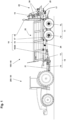
- Figure 1 shows a vehicle combination consisting of a tractor 200 and an agricultural machine 100.
- the tractor 200 is a tractor 30, and the agricultural machine 100 is a manure spreader 40.
- the manure spreader 40 has a drawbar 21, which is coupled to a hitch (not shown in detail) of the tractor 30.
- the tractor has a power take-off in the form of a PTO shaft, to which a drive shaft 13 of the manure spreader 40 is coupled.
- Several drive shafts 13 together form a drive train 15.
- the manure spreader 40 further comprises a loading space 22 with a scraper floor surrounding the loading space floor.
- the scraper floor By means of the scraper floor, the spreading material located in the loading space 22 during operation is fed to a spreading unit 23 arranged at the rear of the loading space 22.
- the spreading unit 23 has two horizontal spreading rollers 24 and two spreading plates 25 mounted underneath.
- the cargo space 22 is mounted on a chassis 26.
- the chassis 26, in turn, is supported by a chassis 11 with two axles 12.
- a generator 16 in the form of a dynamo 20 is coupled to the drive train 15. As soon as an operator starts the power take-off shaft of the tractor 200, the drive shafts 13 of the drive train 15 are set in rotation, and the dynamo 20 coupled to the drive train 15 generates electrical energy.
- the energy thus generated serves both to operate sensors 17 and to operate a signal generator 18 and a controller 19.
- two sensors 17 are provided.
- One sensor 17 is a speed monitor or driving detection sensor integrated into a vehicle axle 12.
- the other sensor 17 is a sensor integrated into the spreading unit 23.
- the rotational movement to be detected can also be recorded in another way, for example by means of a sensor plate (gear ring) wrapped around the brake drum.
- the sensors 17 provide yes/no information as to whether an axle is moving and thus a driving movement or rotational movement is present or not.
- a sensor 17 can also be used, which provides further or different information, for example information about the current speed of the agricultural machine 100.
- the data provided by sensor 17 is transmitted to controller 19. Based on this data, initial information required for activating signal generator 18 is provided. Depending on the design of controller 19, the condition for activating signal generator 18 may be that sensor 17 has detected a driving movement or, in the improved embodiment, a driving movement at a certain minimum speed. Generator 16, sensor 17, signal generator 18, and controller 19 thus form a warning device 10 that is independent of the electrical energy of tractor 200.
- a further sensor can be attached to a working unit of the agricultural machine, in this case, for example, to the spreading unit 14.
- the control system 19 can then be designed such that the signal transmitter is only activated when both a driving movement and a movement of the spreading unit, for example, a rotation of a spreading roller, are detected.
- a delay element is integrated into the controller 19.
- the delay element causes a time-delayed activation of the signal generator 18.
- a time-delayed activation it can be achieved that the signal generator is deactivated with a time delay after the tractor auxiliary drive has been switched off or the agricultural machine 100 has come to a standstill.
- a battery or accumulator can be integrated into the circuit of the warning device 10.
- the accumulator is Generator 16 or dynamo 20 is regularly recharged so that the energy supply to the signal generator 18 is ensured.
- the warning device 10 described in the exemplary embodiment can be integrated into an agricultural machine by the manufacturer, but it can also be provided as a retrofit kit and subsequently attached to an existing agricultural machine.
Landscapes
- Engineering & Computer Science (AREA)
- Chemical & Material Sciences (AREA)
- Combustion & Propulsion (AREA)
- Transportation (AREA)
- Mechanical Engineering (AREA)
- Agricultural Machines (AREA)
Claims (5)
- Machine agricole tractée (100), comprenant :- un châssis (11) avec au moins un essieu de véhicule (12),- une chaîne cinématique (15) pour au moins un groupe de travail (14), la chaîne cinématique (15) comprenant au moins un arbre d'entraînement (13) pouvant être entraîné par un véhicule tracteur (200) et un dispositif d'avertissement (10) autosuffisant en énergie par rapport à une alimentation en énergie électrique du véhicule tracteur (200),caractérisé en ce que le dispositif d'avertissement (10) autonome en énergie comprend au moins les composants suivants:- un générateur (16) couplé à la chaîne cinématique (15) de la machine agricole (100) pour produire de l'énergie électrique;- au moins un capteur (17) pour détecter un mouvement de déplacement de la machine agricole (100) et/ou un mouvement du groupe de travail (14) de la machine agricole (100);- un générateur de signaux (18);- une commande (19) pour l'activation du générateur de signaux (18);- une commande temporelle pour l'activation et/ou la désactivation différée du générateur de signaux (18).
- Machine agricole tractée (100) selon la revendication 1, caractérisée en ce que le générateur (16) est une dynamo (20).
- Machine agricole tractée (100) selon l'une des revendications 1 ou 2, caractérisée en ce que le générateur de signaux (18) est un générateur de signaux optiques et/ou acoustiques, l'alimentation en énergie du générateur de signaux (18) étant de préférence assurée par l'énergie générée par le générateur (16).
- Machine agricole tractée (100) selon l'une des revendications 1 à 3, caractérisée en ce que le capteur (17) est un capteur de mouvement, un capteur de vitesse de rotation, un capteur de proximité, un capteur optique ou un capteur à ultrasons.
- Procédé de fonctionnement d'une machine agricole (100) avec un dispositif d'avertissement (10) autonome en énergie, caractérisé par les étapes de procédé suivantes :- Mise à disposition d'une machine agricole tractée (100), comprenant un châssis (11) avec au moins un essieu de véhicule (12) et une chaîne cinématique (15) pour au moins un groupe de travail (14), la chaîne cinématique (15) comprenant au moins un arbre de transmission (13) pouvant être entraîné par un véhicule tracteur (200);- Produire de l'énergie électrique au moyen d'une génératrice (16) couplée à la chaîne cinématique (15) de la machine agricole (100);- Alimentation d'une commande (19) couplée à la machine agricole avec l'énergie électrique générée par le générateur (16);- Détection d'un mouvement de la machine agricole (100) et/ou d'un groupe de travail (14) de la machine agricole (100) au moyen d'un capteur (17);- Transmission à la commande (19) de valeurs réelles de capteur déterminées par le capteur (17) et/ou de valeurs réelles de fonctionnement du générateur (16);- Comparaison de la valeur réelle du capteur et/ou des valeurs réelles de fonctionnement du générateur avec au moins une valeur de consigne enregistrée dans la commande (19);- Activation d'un générateur de signaux optiques et/ou acoustiques (18) par la commande (19) en cas de détection d'une concordance entre au moins une valeur réelle de capteur et/ou une valeur réelle de générateur avec une valeur de consigne ou une combinaison de valeurs de consigne prédéfinie,l'activation du générateur de signaux optiques et/ou acoustiques (18) étant retardée d'un temps prédéfini après la détection d'une concordance entre au moins une valeur réelle de capteur et/ou une valeur réelle de générateur avec la valeur de consigne prédéfinie ou la combinaison de valeurs de consigne.
Applications Claiming Priority (1)
| Application Number | Priority Date | Filing Date | Title |
|---|---|---|---|
| DE102021126677.7A DE102021126677A1 (de) | 2021-10-14 | 2021-10-14 | Stalldungstreuer mit einer energieautarken Warneinrichtung |
Publications (3)
| Publication Number | Publication Date |
|---|---|
| EP4165970A1 EP4165970A1 (fr) | 2023-04-19 |
| EP4165970B1 true EP4165970B1 (fr) | 2025-05-14 |
| EP4165970C0 EP4165970C0 (fr) | 2025-05-14 |
Family
ID=83898084
Family Applications (1)
| Application Number | Title | Priority Date | Filing Date |
|---|---|---|---|
| EP22201698.2A Active EP4165970B1 (fr) | 2021-10-14 | 2022-10-14 | Épandeur d'étable doté d'un dispositif d'avertissement autonome en énergie |
Country Status (2)
| Country | Link |
|---|---|
| EP (1) | EP4165970B1 (fr) |
| DE (1) | DE102021126677A1 (fr) |
Family Cites Families (10)
| Publication number | Priority date | Publication date | Assignee | Title |
|---|---|---|---|---|
| US3728676A (en) * | 1970-12-02 | 1973-04-17 | Electro Dev Corp | Reverse motion detector |
| US4250486A (en) * | 1979-03-19 | 1981-02-10 | Deere & Company | Vehicle motion alarm |
| EP0181969B1 (fr) | 1984-11-21 | 1988-09-21 | Ford New Holland N.V. | Dispositif de liage automatique pour presses à balles cylindriques |
| DE19718110A1 (de) | 1997-04-29 | 1998-11-05 | Poettinger Ohg Alois | Warneinrichtung für eine verfahrbare landwirtschaftliche Erntemaschine, insbesondere Heuwerbungsmaschine |
| EP1273217A1 (fr) | 2001-07-03 | 2003-01-08 | Lely Enterprises AG | Machine agricole |
| DE202004010713U1 (de) | 2004-07-08 | 2004-09-23 | B. Strautmann & Söhne GmbH u. Co | Breitstreuvorrichtung an einem Streufahrzeug |
| CN202089129U (zh) * | 2011-07-26 | 2011-12-28 | 长沙桑铼特农业机械设备有限公司 | 盘式山地拖拉机 |
| DE102012017401A1 (de) | 2012-09-03 | 2014-03-06 | Alois Pöttinger Maschinenfabrik Ges.m.b.H. | Landwirtschaftliche Maschine |
| IT201900006485A1 (it) * | 2019-05-02 | 2020-11-02 | Bondioli & Pavesi S P A | Sistema di verifica delle condizioni d’impiego di un albero cardanico per un attrezzo collegato ad una motrice, e albero cardanico equipaggiato di tale sistema |
| CN112829582A (zh) * | 2021-02-20 | 2021-05-25 | 上海花豹科技有限公司 | 一种车辆发电系统及发电方法 |
-
2021
- 2021-10-14 DE DE102021126677.7A patent/DE102021126677A1/de active Pending
-
2022
- 2022-10-14 EP EP22201698.2A patent/EP4165970B1/fr active Active
Also Published As
| Publication number | Publication date |
|---|---|
| EP4165970A1 (fr) | 2023-04-19 |
| EP4165970C0 (fr) | 2025-05-14 |
| DE102021126677A1 (de) | 2023-04-20 |
Similar Documents
| Publication | Publication Date | Title |
|---|---|---|
| DE102017211314B4 (de) | Betriebsverfahren, Gespann, Kraftfahrzeug und Zugfahrzeug | |
| EP1466772B1 (fr) | Système d'entraînement pour véhicule | |
| DE112014003835B4 (de) | Antriebssystem für ein Schleppfahrzeug | |
| EP4353906B1 (fr) | Procédé de freinage d'une machine de compactage et machine de compactage | |
| DE102016220905A1 (de) | Vorrichtung und Verfahren zur Regelung des Fahrbetriebs eines Fahrzeugs mit Anhänger | |
| DE102012100541A1 (de) | Fahrbare Vorrichtung zum Zerkleinern von Pflanzen | |
| DE60315227T2 (de) | Vorrichtung zur Regelung eines Hybridfahrzeugs | |
| EP2722261B2 (fr) | Entraînement de manoeuvre doté d'un module de freinage supplémentaire | |
| DE102012006731A1 (de) | Nutzfahrzeug mit einem Hybrid - Elektrozapfwellensystem und Fronthydraulik | |
| EP4165970B1 (fr) | Épandeur d'étable doté d'un dispositif d'avertissement autonome en énergie | |
| DE10260480A1 (de) | Antriebssystem einer selbstfahrenden Arbeitsmaschine | |
| EP2363313B1 (fr) | Dispositif d'entraînement auxiliaire d'un engin de travail mobile | |
| EP3096967B1 (fr) | Chaîne cinématique pour machine de travail mobile entraînée par moteur | |
| DE102016117158B4 (de) | Hydrauliksystem | |
| EP3469872B1 (fr) | Appareil de travail, véhicule de travail doté d'un tel dispositif de travail, système modulaire de fabrication d'appareil de travail ainsi que procédé de fonctionnement d'au moins l'appareil de travail | |
| DE102007037693A1 (de) | Flurförderzeug mit einem Fahrmodus und einem Bremsmodus | |
| DE102019212071A1 (de) | Antriebsanordnung für einen Anhänger und Anhänger | |
| EP3034700B1 (fr) | Systeme d'entrainement pour une machine de traitement de sol | |
| DE102015221996A1 (de) | Anbaugerät für eine landwirtschaftliche und/oder forstwirtschaftliche Arbeitsmaschine und Gespann | |
| DE10242605A1 (de) | Hybridantrieb | |
| EP2033836A2 (fr) | Chariot de manutention doté d'un mode de conduite et d'un mode de frein | |
| EP1387230A1 (fr) | Dispositif pour signale un danger sur une machine agricole | |
| EP3722140A1 (fr) | Procédé de freinage à récupération dans une remorque de véhicule | |
| EP3544842A1 (fr) | Procédé et dispositif pour un entraînement de secours d'un véhicule | |
| DE10302461B4 (de) | Ausfallsichere Stromversorgungsanordnung in einem Kraftfahrzeug |
Legal Events
| Date | Code | Title | Description |
|---|---|---|---|
| PUAI | Public reference made under article 153(3) epc to a published international application that has entered the european phase |
Free format text: ORIGINAL CODE: 0009012 |
|
| STAA | Information on the status of an ep patent application or granted ep patent |
Free format text: STATUS: THE APPLICATION HAS BEEN PUBLISHED |
|
| AK | Designated contracting states |
Kind code of ref document: A1 Designated state(s): AL AT BE BG CH CY CZ DE DK EE ES FI FR GB GR HR HU IE IS IT LI LT LU LV MC ME MK MT NL NO PL PT RO RS SE SI SK SM TR |
|
| STAA | Information on the status of an ep patent application or granted ep patent |
Free format text: STATUS: REQUEST FOR EXAMINATION WAS MADE |
|
| 17P | Request for examination filed |
Effective date: 20230828 |
|
| RBV | Designated contracting states (corrected) |
Designated state(s): AL AT BE BG CH CY CZ DE DK EE ES FI FR GB GR HR HU IE IS IT LI LT LU LV MC ME MK MT NL NO PL PT RO RS SE SI SK SM TR |
|
| GRAP | Despatch of communication of intention to grant a patent |
Free format text: ORIGINAL CODE: EPIDOSNIGR1 |
|
| STAA | Information on the status of an ep patent application or granted ep patent |
Free format text: STATUS: GRANT OF PATENT IS INTENDED |
|
| RIC1 | Information provided on ipc code assigned before grant |
Ipc: B60K 25/06 20060101ALI20240923BHEP Ipc: A01C 19/00 20060101AFI20240923BHEP |
|
| INTG | Intention to grant announced |
Effective date: 20241011 |
|
| GRAJ | Information related to disapproval of communication of intention to grant by the applicant or resumption of examination proceedings by the epo deleted |
Free format text: ORIGINAL CODE: EPIDOSDIGR1 |
|
| STAA | Information on the status of an ep patent application or granted ep patent |
Free format text: STATUS: REQUEST FOR EXAMINATION WAS MADE |
|
| GRAP | Despatch of communication of intention to grant a patent |
Free format text: ORIGINAL CODE: EPIDOSNIGR1 |
|
| STAA | Information on the status of an ep patent application or granted ep patent |
Free format text: STATUS: GRANT OF PATENT IS INTENDED |
|
| INTC | Intention to grant announced (deleted) | ||
| INTG | Intention to grant announced |
Effective date: 20250226 |
|
| GRAS | Grant fee paid |
Free format text: ORIGINAL CODE: EPIDOSNIGR3 |
|
| GRAA | (expected) grant |
Free format text: ORIGINAL CODE: 0009210 |
|
| STAA | Information on the status of an ep patent application or granted ep patent |
Free format text: STATUS: THE PATENT HAS BEEN GRANTED |
|
| AK | Designated contracting states |
Kind code of ref document: B1 Designated state(s): AL AT BE BG CH CY CZ DE DK EE ES FI FR GB GR HR HU IE IS IT LI LT LU LV MC ME MK MT NL NO PL PT RO RS SE SI SK SM TR |
|
| REG | Reference to a national code |
Ref country code: GB Ref legal event code: FG4D Free format text: NOT ENGLISH |
|
| REG | Reference to a national code |
Ref country code: CH Ref legal event code: EP |
|
| REG | Reference to a national code |
Ref country code: DE Ref legal event code: R096 Ref document number: 502022003933 Country of ref document: DE |
|
| REG | Reference to a national code |
Ref country code: IE Ref legal event code: FG4D Free format text: LANGUAGE OF EP DOCUMENT: GERMAN |
|
| U01 | Request for unitary effect filed |
Effective date: 20250612 |
|
| U07 | Unitary effect registered |
Designated state(s): AT BE BG DE DK EE FI FR IT LT LU LV MT NL PT RO SE SI Effective date: 20250624 |
|
| U20 | Renewal fee for the european patent with unitary effect paid |
Year of fee payment: 4 Effective date: 20250903 |
|
| PG25 | Lapsed in a contracting state [announced via postgrant information from national office to epo] |
Ref country code: ES Free format text: LAPSE BECAUSE OF FAILURE TO SUBMIT A TRANSLATION OF THE DESCRIPTION OR TO PAY THE FEE WITHIN THE PRESCRIBED TIME-LIMIT Effective date: 20250514 |
|
| PG25 | Lapsed in a contracting state [announced via postgrant information from national office to epo] |
Ref country code: NO Free format text: LAPSE BECAUSE OF FAILURE TO SUBMIT A TRANSLATION OF THE DESCRIPTION OR TO PAY THE FEE WITHIN THE PRESCRIBED TIME-LIMIT Effective date: 20250814 Ref country code: GR Free format text: LAPSE BECAUSE OF FAILURE TO SUBMIT A TRANSLATION OF THE DESCRIPTION OR TO PAY THE FEE WITHIN THE PRESCRIBED TIME-LIMIT Effective date: 20250815 |
|
| PG25 | Lapsed in a contracting state [announced via postgrant information from national office to epo] |
Ref country code: PL Free format text: LAPSE BECAUSE OF FAILURE TO SUBMIT A TRANSLATION OF THE DESCRIPTION OR TO PAY THE FEE WITHIN THE PRESCRIBED TIME-LIMIT Effective date: 20250514 |
|
| PG25 | Lapsed in a contracting state [announced via postgrant information from national office to epo] |
Ref country code: HR Free format text: LAPSE BECAUSE OF FAILURE TO SUBMIT A TRANSLATION OF THE DESCRIPTION OR TO PAY THE FEE WITHIN THE PRESCRIBED TIME-LIMIT Effective date: 20250514 |
|
| PG25 | Lapsed in a contracting state [announced via postgrant information from national office to epo] |
Ref country code: RS Free format text: LAPSE BECAUSE OF FAILURE TO SUBMIT A TRANSLATION OF THE DESCRIPTION OR TO PAY THE FEE WITHIN THE PRESCRIBED TIME-LIMIT Effective date: 20250814 |
|
| PG25 | Lapsed in a contracting state [announced via postgrant information from national office to epo] |
Ref country code: IS Free format text: LAPSE BECAUSE OF FAILURE TO SUBMIT A TRANSLATION OF THE DESCRIPTION OR TO PAY THE FEE WITHIN THE PRESCRIBED TIME-LIMIT Effective date: 20250914 |
|
| REG | Reference to a national code |
Ref country code: CH Ref legal event code: U11 Free format text: ST27 STATUS EVENT CODE: U-0-0-U10-U11 (AS PROVIDED BY THE NATIONAL OFFICE) Effective date: 20251101 |
|
| PG25 | Lapsed in a contracting state [announced via postgrant information from national office to epo] |
Ref country code: SM Free format text: LAPSE BECAUSE OF FAILURE TO SUBMIT A TRANSLATION OF THE DESCRIPTION OR TO PAY THE FEE WITHIN THE PRESCRIBED TIME-LIMIT Effective date: 20250514 |
|
| PGFP | Annual fee paid to national office [announced via postgrant information from national office to epo] |
Ref country code: CH Payment date: 20251101 Year of fee payment: 4 |
|
| PG25 | Lapsed in a contracting state [announced via postgrant information from national office to epo] |
Ref country code: CZ Free format text: LAPSE BECAUSE OF FAILURE TO SUBMIT A TRANSLATION OF THE DESCRIPTION OR TO PAY THE FEE WITHIN THE PRESCRIBED TIME-LIMIT Effective date: 20250514 |
|
| PG25 | Lapsed in a contracting state [announced via postgrant information from national office to epo] |
Ref country code: SK Free format text: LAPSE BECAUSE OF FAILURE TO SUBMIT A TRANSLATION OF THE DESCRIPTION OR TO PAY THE FEE WITHIN THE PRESCRIBED TIME-LIMIT Effective date: 20250514 |
|
| PLBE | No opposition filed within time limit |
Free format text: ORIGINAL CODE: 0009261 |
|
| STAA | Information on the status of an ep patent application or granted ep patent |
Free format text: STATUS: NO OPPOSITION FILED WITHIN TIME LIMIT |
|
| REG | Reference to a national code |
Ref country code: CH Ref legal event code: L10 Free format text: ST27 STATUS EVENT CODE: U-0-0-L10-L00 (AS PROVIDED BY THE NATIONAL OFFICE) Effective date: 20260325 |
|
| 26N | No opposition filed |
Effective date: 20260217 |