EP4166384B1 - Fahrzeugbatteriewechselverfahren, batteriewechselwagen und elektronisches gerät - Google Patents
Fahrzeugbatteriewechselverfahren, batteriewechselwagen und elektronisches gerät Download PDFInfo
- Publication number
- EP4166384B1 EP4166384B1 EP21912342.9A EP21912342A EP4166384B1 EP 4166384 B1 EP4166384 B1 EP 4166384B1 EP 21912342 A EP21912342 A EP 21912342A EP 4166384 B1 EP4166384 B1 EP 4166384B1
- Authority
- EP
- European Patent Office
- Prior art keywords
- battery
- vehicle
- swapping
- swapped
- van
- Prior art date
- Legal status (The legal status is an assumption and is not a legal conclusion. Google has not performed a legal analysis and makes no representation as to the accuracy of the status listed.)
- Active
Links
Images


Classifications
-
- B—PERFORMING OPERATIONS; TRANSPORTING
- B60—VEHICLES IN GENERAL
- B60L—PROPULSION OF ELECTRICALLY-PROPELLED VEHICLES; SUPPLYING ELECTRIC POWER FOR AUXILIARY EQUIPMENT OF ELECTRICALLY-PROPELLED VEHICLES; ELECTRODYNAMIC BRAKE SYSTEMS FOR VEHICLES IN GENERAL; MAGNETIC SUSPENSION OR LEVITATION FOR VEHICLES; MONITORING OPERATING VARIABLES OF ELECTRICALLY-PROPELLED VEHICLES; ELECTRIC SAFETY DEVICES FOR ELECTRICALLY-PROPELLED VEHICLES
- B60L53/00—Methods of charging batteries, specially adapted for electric vehicles; Charging stations or on-board charging equipment therefor; Exchange of energy storage elements in electric vehicles
- B60L53/80—Exchanging energy storage elements, e.g. removable batteries
-
- B—PERFORMING OPERATIONS; TRANSPORTING
- B60—VEHICLES IN GENERAL
- B60L—PROPULSION OF ELECTRICALLY-PROPELLED VEHICLES; SUPPLYING ELECTRIC POWER FOR AUXILIARY EQUIPMENT OF ELECTRICALLY-PROPELLED VEHICLES; ELECTRODYNAMIC BRAKE SYSTEMS FOR VEHICLES IN GENERAL; MAGNETIC SUSPENSION OR LEVITATION FOR VEHICLES; MONITORING OPERATING VARIABLES OF ELECTRICALLY-PROPELLED VEHICLES; ELECTRIC SAFETY DEVICES FOR ELECTRICALLY-PROPELLED VEHICLES
- B60L53/00—Methods of charging batteries, specially adapted for electric vehicles; Charging stations or on-board charging equipment therefor; Exchange of energy storage elements in electric vehicles
- B60L53/30—Constructional details of charging stations
- B60L53/35—Means for automatic or assisted adjustment of the relative position of charging devices and vehicles
- B60L53/36—Means for automatic or assisted adjustment of the relative position of charging devices and vehicles by positioning the vehicle
-
- B—PERFORMING OPERATIONS; TRANSPORTING
- B60—VEHICLES IN GENERAL
- B60L—PROPULSION OF ELECTRICALLY-PROPELLED VEHICLES; SUPPLYING ELECTRIC POWER FOR AUXILIARY EQUIPMENT OF ELECTRICALLY-PROPELLED VEHICLES; ELECTRODYNAMIC BRAKE SYSTEMS FOR VEHICLES IN GENERAL; MAGNETIC SUSPENSION OR LEVITATION FOR VEHICLES; MONITORING OPERATING VARIABLES OF ELECTRICALLY-PROPELLED VEHICLES; ELECTRIC SAFETY DEVICES FOR ELECTRICALLY-PROPELLED VEHICLES
- B60L53/00—Methods of charging batteries, specially adapted for electric vehicles; Charging stations or on-board charging equipment therefor; Exchange of energy storage elements in electric vehicles
- B60L53/30—Constructional details of charging stations
- B60L53/35—Means for automatic or assisted adjustment of the relative position of charging devices and vehicles
- B60L53/37—Means for automatic or assisted adjustment of the relative position of charging devices and vehicles using optical position determination, e.g. using cameras
-
- B—PERFORMING OPERATIONS; TRANSPORTING
- B60—VEHICLES IN GENERAL
- B60L—PROPULSION OF ELECTRICALLY-PROPELLED VEHICLES; SUPPLYING ELECTRIC POWER FOR AUXILIARY EQUIPMENT OF ELECTRICALLY-PROPELLED VEHICLES; ELECTRODYNAMIC BRAKE SYSTEMS FOR VEHICLES IN GENERAL; MAGNETIC SUSPENSION OR LEVITATION FOR VEHICLES; MONITORING OPERATING VARIABLES OF ELECTRICALLY-PROPELLED VEHICLES; ELECTRIC SAFETY DEVICES FOR ELECTRICALLY-PROPELLED VEHICLES
- B60L2200/00—Type of vehicles
- B60L2200/40—Working vehicles
-
- Y—GENERAL TAGGING OF NEW TECHNOLOGICAL DEVELOPMENTS; GENERAL TAGGING OF CROSS-SECTIONAL TECHNOLOGIES SPANNING OVER SEVERAL SECTIONS OF THE IPC; TECHNICAL SUBJECTS COVERED BY FORMER USPC CROSS-REFERENCE ART COLLECTIONS [XRACs] AND DIGESTS
- Y02—TECHNOLOGIES OR APPLICATIONS FOR MITIGATION OR ADAPTATION AGAINST CLIMATE CHANGE
- Y02T—CLIMATE CHANGE MITIGATION TECHNOLOGIES RELATED TO TRANSPORTATION
- Y02T10/00—Road transport of goods or passengers
- Y02T10/60—Other road transportation technologies with climate change mitigation effect
- Y02T10/70—Energy storage systems for electromobility, e.g. batteries
-
- Y—GENERAL TAGGING OF NEW TECHNOLOGICAL DEVELOPMENTS; GENERAL TAGGING OF CROSS-SECTIONAL TECHNOLOGIES SPANNING OVER SEVERAL SECTIONS OF THE IPC; TECHNICAL SUBJECTS COVERED BY FORMER USPC CROSS-REFERENCE ART COLLECTIONS [XRACs] AND DIGESTS
- Y02—TECHNOLOGIES OR APPLICATIONS FOR MITIGATION OR ADAPTATION AGAINST CLIMATE CHANGE
- Y02T—CLIMATE CHANGE MITIGATION TECHNOLOGIES RELATED TO TRANSPORTATION
- Y02T10/00—Road transport of goods or passengers
- Y02T10/60—Other road transportation technologies with climate change mitigation effect
- Y02T10/7072—Electromobility specific charging systems or methods for batteries, ultracapacitors, supercapacitors or double-layer capacitors
Definitions
- This application relates to the technical field of vehicle charging, and in particular, to a vehicle battery swapping method, a battery swapping van, an electronic device, and a storage medium.
- battery electric vehicles have been widely used as engineering transport vehicles, for example, for purposes of transportation in mining regions.
- a battery of the vehicle needs to be swapped when the battery is in a low state of charge.
- a mobile battery swapping van In swapping a battery, the low-state-of-charge battery in the vehicle needs to be removed by using a forklift, and then a battery in the battery swapping van is mounted into the vehicle.
- An example of such state of the art is found in CN 111717 063 A .
- the process of swapping the battery using a forklift involves manual handling, and is prone to failure of mounting the battery in place.
- the location of the battery needs to be further adjusted manually, which is time-consuming and labor-intensive.
- an objective of this application is to provide a vehicle battery swapping method and a battery swapping van to implement precise positioning during battery swapping, and improve efficiency of the battery swapping.
- this application Compared with the prior art, this application possesses the following advantages:
- the coordinate origin of the hoister of the battery swapping van is connected to the reference point of the battery-to-be-swapped vehicle, thereby avoiding problems such as inaccurate positioning in the GPS and the image technology caused by low visibility, signal interference, and other reasons, so as to implement precise positioning of the battery swapping van and the battery-to-be-swapped vehicle. Therefore, automatic, accurate, and efficient battery swap operations can be performed by using the hoister.
- Power batteries are not only used in passenger vehicles, but also widely used in commercial vehicles, such as engineering vehicles and mining vehicles. With the wide use of power batteries, more attention has been paid to how to quickly and accurately swap a power battery.
- the power battery used therein is characterized by a small capacity and a low weight, and the operating environment of the passenger vehicle is relatively simple and fixed.
- charging stations may be constructed to swap the power battery, or charging piles may be constructed for charging the battery, or even a driver may replace the power battery manually.
- the work regions of the vehicles occupy a large area, and are dispersive, without following a fixed operating route.
- the commercial vehicles are generally unable to make full use of the fixed charging piles and charging stations, and need to swap batteries by using a mobile battery swapping van.
- the battery In view of the capacity and weight of the battery, the battery is not manually swappable, but needs to be transported by a forklift, and then the mounting location of the battery needs to be further adjusted manually, which is time-consuming and labor-intensive.
- problems due to a complex environment and heavy dust in the work region, problems such as signal interference and low visibility are prone to arise. Therefore, the existing GPS or image technology is unable to accurately position the vehicle and the battery swapping van. Consequently, an automatic transit and mounting device is unable to determine the mounting location of the battery accurately, thereby restricting the use of the automatic transit and mounting device in the battery swapping van.
- the vehicle can be accurately positioned by means of a positioning line, and that the battery swap operation can be automatically performed by using a hoister.
- a vehicle battery swapping method disclosed in the embodiments of this application may be used, but is not limited to be used, for commercial vehicles, passenger vehicles, and the like.
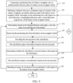
- FIG. 1 is a flowchart of a vehicle battery swapping method according to an embodiment of this application
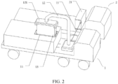
- FIG. 2 is a schematic structural diagram of a battery swapping van located in a battery swap position and a battery-to-be-swapped vehicle according to an embodiment of this application
- FIG. 3 is a local enlarged view of a joint between a positioning line and a battery-to-be-swapped vehicle according to an embodiment of this application
- FIG. 4 is a schematic measurement diagram of a positioning line according to an embodiment of this application.
- An embodiment of this application provides a vehicle battery swapping method.
- a console When a battery in a vehicle is in a low state of charge, the vehicle sends a battery swap request. After receiving the battery swap request, a console sends the battery swap request to a battery swapping van 1.
- the battery swapping van 1 moves to a battery swap position.
- the console is capable of dispatching, and is configured to receive a signal and send an instruction.
- the console may be a remote server, a mobile device, a dispatching room, or the like.
- a vehicle with a battery to be swapped out is referred to as a battery-to-be-swapped vehicle 2
- the battery that needs to be swapped out in the battery-to-be-swapped vehicle 2 is referred to as a first battery 21.
- the battery swap position is a location near the battery-to-be-swapped vehicle 2, for example, a location that is approximately 1 to 2 meters distant from the battery-to-be-swapped vehicle 2.
- the console may first determine the location of the battery swapping van 1, and then send the battery swap request to the battery swapping van 1 closest to the battery-to-be-swapped vehicle 2.
- a positioning line 11 of a battery swapping van 1 is connected to a predetermined reference point of a battery-to-be-swapped vehicle 2.
- the positioning line 11 may be a physical connection line or a virtual connection line, one end of which is located at a coordinate origin of a hoister 12 of the battery swapping van 1, and the other end of which is connected to the predetermined reference point of the battery-to-be-swapped vehicle 2.
- the hoister 12 may be an industrial robot.
- the coordinate origin of the hoister may be an origin of a base coordinate system (a rectangular coordinate system designed to describe a robot body movement, benchmarked against an installation pedestal) of the industrial robot.
- the predetermined reference point of the battery-to-be-swapped vehicle 2 may be located on a positioning reference block (see FIG. 3 ) of a battery pack frame of the first battery 21, and all batteries have the same positioning reference point.
- step 120 a distance between a coordinate origin of a hoister 12 of the battery swapping van 1 and the reference point of the battery-to-be-swapped vehicle 2, and angles of the positioning line 11 with respect to a travel direction x, a longitudinal direction y, and a vertical direction z, respectively, of the battery-to-be-swapped vehicle 2, are obtained.
- the positioning line 11 is a tensile physical connection line.
- a force F on the positioning line 11 may be measured by a force sensor.
- an angle ⁇ of the positioning line 11 with respect to the travel direction x, an angle ⁇ of the positioning line with respect to the longitudinal direction y, and an angle ⁇ of the positioning line with respect to the vertical direction z, respectively, of the battery-to-be-swapped vehicle 2 are obtained, as shown in FIG. 4 .
- the force F on the positioning line 11 may be converted into an elongation to determine the distance between the coordinate origin of the hoister 12 of the battery swapping van 1 and the reference point of the battery-to-be-swapped vehicle 2.
- the positioning line 11 may be a virtual connection line.
- the positioning line 11 is a laser ray.
- the distance between the coordinate origin of the hoister 12 of the battery swapping van 1 and the reference point of the battery-to-be-swapped vehicle 2 can be obtained by using an instrument such as a laser rangefinder, and the angles of the positioning line 11 with respect to the x-direction, y-direction, and z-direction, respectively, can be obtained by using a laser goniometer.
- the obtained distance between the coordinate origin of the hoister 12 of the battery swapping van 1 and the reference point of the battery-to-be-swapped vehicle 2 will be decomposed into components in the x-direction, y-direction, and z-direction, respectively, for ease of subsequent calculation.
- a moving track P of an end effector 121 of the hoister 12 is determined based on the obtained distance and angles.
- the hoister 12 may be an industrial robot, and the end effector 121 may be a hand of the industrial robot, and is configured to perform specific tasks such as directly gripping a component.
- the end effector 121 is a gripper capable of gripping a battery.
- an initial moving track P 0 of the end effector 121 of the hoister 12 is calculated first, and the initial moving track P 0 is stored in the memory.
- the positioning line 11 is a tensile physical connection line
- known values are the force F 0 on the positioning line 11, the angle ⁇ 0 of the positioning line 11 with respect to the x-direction, the angle ⁇ 0 of the positioning line 11 with respect to the y-direction, and the angle ⁇ 0 of the positioning line with respect to the z-direction. That is, a terminal pose of the end effector 121 is known. Therefore, the initial moving track P 0 (F 0 , ⁇ 0 , ⁇ 0 , ⁇ 0 ) of the end effector 121 can be calculated by using a robot kinematics inverse solution.
- the moving track P is provided to the end effector 121 of the hoister 12 so that the end effector 121 replaces a first battery 21 of the battery-to-be-swapped vehicle 2 with a second battery 13 based on the moving track P.
- the processor provides the moving track P to a controller of the hoister 12.
- the controller controls the end effector 121 to move based on the moving track P.
- the end effector 121 grips the first battery 21 first, and removes the first battery from the battery-to-be-swapped vehicle 2.
- the end effector 121 grips the second battery 13 and hoists and mounts the second battery 13 to the battery-to-be-swapped vehicle 2 based on the moving track P.
- the position of the coordinate origin of the hoister 12 of the battery swapping van 1 with respect to the reference point of the battery-to-be-swapped vehicle 2 is obtained by using the positioning line 11. In this way, the position of the hoister 12 with respect to the battery-to-be-swapped vehicle 2 can be determined accurately, thereby determining the moving track of the hoister 12 and implementing automatic, accurate, and efficient battery swap operations.
- FIG. 5 shows a flowchart of a vehicle battery swapping method according to some embodiments of this application.
- the positioning line 11 may be removed from the battery-to-be-swapped vehicle 2 in step 150 to get ready for a battery swap operation.
- step 140 may be performed by stopping obtaining the distance between the coordinate origin of the hoister 12 of the battery swapping van 1 and the reference point of the battery-to-be-swapped vehicle 2 as well as the angles of the positioning line 11 with respect to the travel direction x, the longitudinal direction y, and the vertical direction z, respectively, of the battery-to-be-swapped vehicle 2.
- step 140 may further include the following steps: step 141: providing the moving track P to the end effector 121; step 142: the end effector 121 grips the first battery 21 based on the moving track P; step 143: determining whether the end effector 121 is moved in place with respect to the first battery 21; and step 144: the end effector 121 mounts the second battery 13 based on the moving track P.
- step 143 based on the location of the end effector 121 of the hoister 12 with respect to the first battery 21, it may be determined whether the end effector 121 is moved in place with respect to the first battery 21. If the end effector is moved in place, the process goes to step 144; if the end effector is not moved in place, the process returns to step 120 to re-obtain the distance between the coordinate origin of the hoister 12 of the battery swapping van 1 and the reference point of the battery-to-be-swapped vehicle 2, and angles of the positioning line 11 with respect to the travel direction x, the longitudinal direction y, and the vertical direction z, respectively, of the battery-to-be-swapped vehicle 2, so as to ensure the end effector 121 to accurately grip the first battery 21.
- the step of determining whether the end effector 121 is moved in place with respect to the first battery 21 ensures that the end effector can accurately grip the first battery 21, and also ensures accuracy of the moving track P of the end effector 121.
- step 140 may futher includes the following step: step 145: obtaining an image of a location of the second battery 13 with respect to the battery-to-be-swapped vehicle 2.
- the image of the location of the second battery 13 with respect to the battery-to-be-swapped vehicle 2 that is, an image of a mounting location
- the moving track P of the end effector 121 of the hoister 12 is corrected based on the image of the mounting position.
- the obtained image of the location of the second battery 13 with respect to the battery-to-be-swapped vehicle 2 is compared with an image of the location of the battery mounted in place in the battery-to-be-swapped vehicle 2.
- a comparison result shows that a deviation between the two images is within an allowed range
- the mounting of the second battery 13 is continued. If the comparison result shows that the deviation between the two images is beyond the allowed range, the moving track P of the end effector 121 needs to be adjusted.
- the moving track of the end effector 121 of the hoister 12 is subjected to feedback correction by using the obtained image of the location of the second battery 13 with respect to the battery-to-be-swapped vehicle 2, thereby ensuring that the second battery is accurately mounted in the battery-to-be-swapped vehicle.
- the method may further include: conveying the first battery 21 to a stow location of the battery swapping van 1, and conveying the second battery 13 to a battery swapping window 15 of the battery swapping van 1.
- the end effector 121 hoists the first battery 21 onto the battery swapping van 1.
- the first battery 21 is conveyed to the stow location by a battery conveyance unit 14 in the battery swapping van 1.
- the second battery 13 is conveyed to a battery swapping window 15 through the battery conveyance unit 14, so as to be available for being gripped by the end effector 121 and mounted onto the battery-to-be-swapped vehicle 2.
- the first battery and the second battery can be automatically managed and invoked, thereby improving the efficiency of battery swapping.
- this application further provides a battery swapping van for swapping a vehicle battery.
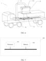
- FIG. 6 shows a battery swapping van for swapping a vehicle battery.
- the battery swapping van 1 includes: a positioning line 11 (not shown in FIG. 6 ), a hoister 12, a second battery 13, a processor 101 (not shown in FIG. 6 ), and a positioning unit 16.
- the hoister 12 includes an end effector 121 adapted to clamp a first battery 21 and a second battery 13.
- One end of the positioning line 11 is located at a coordinate origin of the hoister 12, and the other end is connected to a preset reference point of the battery-to-be-swapped vehicle 2.
- the positioning unit 16 is preferably disposed in a pedestal of the hoister 12, and is configured to measure a distance along the positioning line 11 and angles of the positioning line 11 with respect to a travel direction x, a longitudinal direction y, and a vertical direction z, respectively, of a battery-to-be-swapped vehicle 2.
- the positioning unit 16 includes, but is not limited to, a location sensor, a force sensor, and an angle sensor.
- the processor 101 is configured to receive the distance and angles measured by the positioning unit 16, and determine, based on the obtained distance and angles, a moving track P of the end effector 121 of the hoister 12, and cause the end effector 121 to move based on the moving track P, so as to replace the first battery 21 with the second battery 13.
- the hoister 12 may be a robotic arm.
- the end effector 121 of the hoister can perform translational movement in the x-direction and the y-direction, and can rotate around the z-direction.
- the position of the coordinate origin of the hoister 12 of the battery swapping van 1 with respect to the reference point of the battery-to-be-swapped vehicle 2 can be accurately obtained by using the positioning line 11 of the battery swapping van 1, and the hoister 12 can perform battery swap operations accurately, automatically, and efficiently.
- an imaging device is disposed at the end effector 121 of the hoister 12.
- the imaging device is configured to obtain an image of a location of the second battery 13 with respect to the battery-to-be-swapped vehicle 2, and send the obtained image of the location to the processor 101.
- the processor 101 compares the obtained image of the location with an image of the location of the battery mounted in place, and determines whether a deviation of the location of the second battery 13 with respect to the battery-to-be-swapped vehicle 2 falls within an allowable range.
- image data of the location of the second battery 13 with respect to the battery-to-be-swapped vehicle 2 can be obtained during a battery swap operation.
- the data is fed back to the processor 101 to correct the moving track P, thereby forming closed-loop control on the end effector.
- the battery swapping van 1 may further include a battery conveyance unit 14.
- the battery conveyance unit 14 may include an actuation mechanism and a support element.
- the actuation mechanism may be a motor
- the support element may be a roller.
- the roller is arranged along a conveyance rail.
- the motor drives the roller to rotate, the first battery 21 can be conveyed to a stow location, and the second battery 13 can be conveyed to a battery swapping window 15.
- the battery conveyance unit 14 may be configured to communicate with the processor 101 to automatically convey the battery.
- the first battery and the second battery can be automatically managed and invoked, thereby improving the efficiency of battery swapping.
- a location sensor may be disposed at the end effector 121 of the hoister 12.
- the location sensor is configured to detect a location of the end effector 121 of the hoister 12 with respect to the first battery 21 in the battery-to-be-swapped vehicle 2, so as to determine whether the end effector 121 is moved in place with respect to the first battery 21.
- the disposed location sensor ensures that the end effector 121 accurately grips the first battery 21, and also ensures accuracy of the moving track.
- FIG. 7 shows an electronic device 100 includes: a processor 101; and a memory 102 communicationally connected to the processor 101.
- the memory 102 stores an instruction executable by the processor 101.
- the instruction When the instruction is executed by the processor 101, the instruction enables the processor 101 to perform the vehicle battery swapping method according to the embodiments of this application.
- the processor 101 is electrically connected to the memory 102 directly or indirectly to transmit or exchange data.
- such components may be electrically connected to each other by one or more communications buses or signal buses.
- the method for correcting a state of charge of the battery includes at least one software function module that can be stored in the memory 102 in the form of software or firmware.
- the processor 101 may be an integrated circuit chip capable of processing signals.
- the processor 101 may be a general-purpose processor, such as a central processing unit (CPU) or a network processor, network processor (NP); or may be a digital signal processor, an application-specific integrated circuit, a field programmable gate array or other programmable logical device, a discrete gate or a transistor logical device, or a discrete hardware component.
- the processor can implement or perform the methods, steps, and logical block diagrams disclosed in the embodiments of this application.
- the general-purpose processor may be a microprocessor, or the processor may be any conventional processor or the like.
- the memory 102 may store various software programs and modules, such as program instructions or modules corresponding to the vehicle battery swapping method and device according to the embodiments of this application.
- the processor 101 By running the software programs and modules stored in the memory 102, the processor 101 performs various functionalities and data processing, that is, implements the method according to the embodiments of this application.
- the memory 102 may be, but is not limited to, a random access memory (RAM), a read-only memory(ROM), a programmable read-only memory (PROM), an erasable programmable read-only memory (EPROM), an electric erasable programmable read-only memory (EEPROM), or the like.
- RAM random access memory
- ROM read-only memory
- PROM programmable read-only memory
- EPROM erasable programmable read-only memory
- EEPROM electric erasable programmable read-only memory
Landscapes
- Engineering & Computer Science (AREA)
- Power Engineering (AREA)
- Transportation (AREA)
- Mechanical Engineering (AREA)
- Charge And Discharge Circuits For Batteries Or The Like (AREA)
- Vehicle Cleaning, Maintenance, Repair, Refitting, And Outriggers (AREA)
- Electric Propulsion And Braking For Vehicles (AREA)
- Arrangement Or Mounting Of Propulsion Units For Vehicles (AREA)
Claims (7)
- Verfahren zum Wechseln einer ersten Batterie (21) mit niedrigem Ladezustand bei einem Fahrzeug (2), dessen Batterie gewechselt werden soll, gegen eine neue zweite Batterie (13) aus einem mobilen Batteriewechselwagen (1), wobei das Verfahren umfasst:Bewegen des mobilen Batteriewechselwagens (1) zu einer Batteriewechselposition in der Nähe des Fahrzeugs (2), dessen Batterie gewechselt werden soll;Verbinden einer Positionierungslinie (11) des mobilen Batteriewechselwagens (1) mit einem vorbestimmten Referenzpunkt des Fahrzeugs (2), dessen Batterie gewechselt werden soll;Ermitteln von einem Abstand zwischen einem Koordinatenursprung eines Hebezeugs (12) des mobilen Batteriewechselwagens (1) und dem Referenzpunkt des Fahrzeugs (2), dessen Batterie gewechselt werden soll, sowie von jeweiligen Winkeln der Positionierungslinie (11) in Bezug auf eine Fahrtrichtung (x), eine Längsrichtung (y) bzw. eine vertikale Richtung (z) des Fahrzeugs (2), dessen Batterie gewechselt werden soll; undBestimmen einer Bewegungsbahn (P) eines Endeffektors (121) des Hebezeugs (12) auf der Grundlage des ermittelten Abstands und der ermittelten Winkel, wobei der Endeffektor dazu ausgelegt ist, die erste Batterie (21) und die zweite Batterie (13) festzuklemmen;Korrigieren der Bewegungsbahn (P) des Endeffektors (121) des Hebezeugs (12) auf der Grundlage einer Abbildung einer Montagestellung, wobei die Abbildung der Montagestellung eine Abbildung einer Stellung der zweiten Batterie (13) in Bezug auf das Fahrzeug (2), dessen Batterie gewechselt werden soll, ist und durch eine Abbildungsvorrichtung erhalten wird; undBewegen des Endeffektors (121) des Hebezeugs (12) entlang der Bewegungsbahn (P), um die erste Batterie (21) des Fahrzeugs (2), dessen Batterie gewechselt werden soll, durch die zweite Batterie (13) zu ersetzen.
- Verfahren nach Anspruch 1, wobei das Verfahren ferner umfasst:
Entfernen der Positionierungslinie (11) von dem Fahrzeug (2), dessen Batterie gewechselt werden soll, nachdem die Bewegungsbahn (P) des Endeffektors (121) des Hebezeugs (12) bestimmt wurde. - Verfahren nach einem der vorhergehenden Ansprüche, wobei das Verfahren ferner umfasst: Bestimmen, auf der Grundlage einer Stellung des Endeffektors (121) des Hebezeugs (12) in Bezug auf die erste Batterie (21), ob der Endeffektor (121) in seiner Stellung in Bezug auf die erste Batterie (21) bewegt wird.
- Verfahren nach einem der vorhergehenden Ansprüche, wobei das Verfahren ferner umfasst: Fördern der ersten Batterie (21) zu einer Abstellstellung des Batteriewechselwagens (1), und Fördern der zweiten Batterie (13) zu einem Batteriewechselfenster (15) des Batteriewechselwagens (1).
- Batteriewechselwagen (1), der zur Durchführung eines Verfahrens nach einem der vorhergehenden Ansprüche ausgelegt ist, wobei der Batteriewechselwagen (1) enthält:ein Hebezeug (12) mit einem Endeffektor (121), der dazu ausgelegt ist, eine erste Batterie (21) und eine zweite Batterie (13) festzuklemmen;dadurch gekennzeichnet, dass der Batteriewechselwagen (1) ferner enthält:eine Positionierungslinie (11), wobei ein Ende der Positionierungslinie (11) an einem Koordinatenursprung des Hebezeugs (12) angeordnet ist;eine Positionierungseinheit (16), die dazu ausgelegt ist, einen Abstand entlang der Positionierungslinie (11) und jeweilige Winkel der Positionierungslinie (11) in Bezug auf eine Fahrtrichtung (x), eine Längsrichtung (y) bzw. eine vertikale Richtung (z) eines Fahrzeugs (2), dessen Batterie gewechselt werden soll, zu messen;einen Prozessor (101), der dazu ausgelegt ist, den von der Positionierungseinheit (16) gemessenen Abstand und die gemessenen Winkel zu empfangen und auf der Grundlage des ermittelten Abstands und der ermittelten Winkel eine Bewegungsbahn (P) des Endeffektors (121) des Hebezeugs (12) zu bestimmen und den Endeffektor (121) zu veranlassen, sich auf der Grundlage der Bewegungsbahn (P) zu bewegen; undeine Abbildungsvorrichtung, die an dem Endeffektor (121) des Hebezeugs (12) angeordnet ist, wobei die Abbildungsvorrichtung dazu ausgelegt ist, eine Abbildung einer Stellung der zweiten Batterie (13) in Bezug auf das Fahrzeug (2), dessen Batterie gewechselt werden soll, zu erhalten.
- Batteriewechselwagen (1) nach Anspruch 5, wobei der Batteriewechselwagen (1) ferner eine Batteriefördereinheit (14) enthält, wobei die Batteriefördereinheit (14) einen Betätigungsmechanismus und ein Auflageelement enthält, wobei der Betätigungsmechanismus dazu ausgelegt ist, das Auflageelement zu betätigen, um es derart zu bewegen, dass die erste Batterie (21) zu einer Abstellstellung gefördert wird und die zweite Batterie (13) zu einem Batteriewechselfenster (15) gefördert wird.
- Batteriewechselwagen nach Anspruch 5 oder 6, wobei ein Positionssensor an dem Endeffektor (121) des Hebezeugs (12) angeordnet ist und der Positionssensor dazu ausgelegt ist, eine Stellung des Endeffektors (121) des Hebezeugs (12) in Bezug auf die erste Batterie (21) in dem Fahrzeug (2), dessen Batterie gewechselt werden soll, zu erfassen.
Priority Applications (1)
| Application Number | Priority Date | Filing Date | Title |
|---|---|---|---|
| HUE21912342A HUE066673T2 (hu) | 2021-08-25 | 2021-08-25 | Jármûakkumulátor-cserélõ eljárás, akkumulátorcserélõ jármû és elektronikus készülék |
Applications Claiming Priority (1)
| Application Number | Priority Date | Filing Date | Title |
|---|---|---|---|
| PCT/CN2021/114543 WO2023023977A1 (zh) | 2021-08-25 | 2021-08-25 | 用于更换车辆的电池的方法、换电车及电子设备 |
Publications (3)
| Publication Number | Publication Date |
|---|---|
| EP4166384A1 EP4166384A1 (de) | 2023-04-19 |
| EP4166384A4 EP4166384A4 (de) | 2023-05-17 |
| EP4166384B1 true EP4166384B1 (de) | 2024-03-20 |
Family
ID=85286941
Family Applications (1)
| Application Number | Title | Priority Date | Filing Date |
|---|---|---|---|
| EP21912342.9A Active EP4166384B1 (de) | 2021-08-25 | 2021-08-25 | Fahrzeugbatteriewechselverfahren, batteriewechselwagen und elektronisches gerät |
Country Status (6)
| Country | Link |
|---|---|
| US (1) | US12172545B2 (de) |
| EP (1) | EP4166384B1 (de) |
| CN (1) | CN116601044A (de) |
| ES (1) | ES2981582T3 (de) |
| HU (1) | HUE066673T2 (de) |
| WO (1) | WO2023023977A1 (de) |
Families Citing this family (4)
| Publication number | Priority date | Publication date | Assignee | Title |
|---|---|---|---|---|
| CN116674420B (zh) * | 2023-06-27 | 2025-08-01 | 湖南行必达网联科技有限公司 | 换电站控制方法、装置、系统及换电站 |
| CN119489718A (zh) * | 2023-08-18 | 2025-02-21 | 宁德时代新能源科技股份有限公司 | 换电站的车辆定位方法、设备、存储介质以及换电站 |
| US12606988B2 (en) * | 2023-09-29 | 2026-04-21 | Caterpillar Inc. | Hot swappable battery configuration |
| CN118386907B (zh) * | 2024-06-25 | 2025-03-14 | 国网天津市电力公司滨海供电分公司 | 一种电动汽车自动充电系统 |
Family Cites Families (20)
| Publication number | Priority date | Publication date | Assignee | Title |
|---|---|---|---|---|
| TW412097U (en) * | 1999-01-28 | 2000-11-11 | Ind Tech Res Inst | Select-type battery-charging station for managing and switching the batteries of electric vehicles |
| WO2009086495A2 (en) * | 2007-12-28 | 2009-07-09 | Sam Stathis | Robotic arm for accurate positioning in three-dimensional space, measurement of three-dimensional coordinates, and remote tooling operations in three-dimensional space |
| US8006793B2 (en) * | 2008-09-19 | 2011-08-30 | Better Place GmbH | Electric vehicle battery system |
| KR101496445B1 (ko) * | 2013-04-12 | 2015-03-02 | 에스티엑스조선해양 주식회사 | 이동 로봇의 위치 및 자세 인식 장치 및 방법 |
| US10022867B2 (en) * | 2014-11-11 | 2018-07-17 | X Development Llc | Dynamically maintaining a map of a fleet of robotic devices in an environment to facilitate robotic action |
| US9187004B1 (en) * | 2015-04-03 | 2015-11-17 | Harold William Davis | Electric vehicle carousel battery exchange/charging system |
| US9868421B2 (en) * | 2015-06-17 | 2018-01-16 | Ample, Inc. | Robot assisted modular battery interchanging system |
| US9776326B2 (en) * | 2015-10-07 | 2017-10-03 | X Development Llc | Battery and hard drive exchange station for robots |
| DE102015225789A1 (de) * | 2015-12-17 | 2017-06-22 | Volkswagen Aktiengesellschaft | Mobiler Energiespeicher und Verfahren zum Bereitstellen von Energie für einen Verbraucher |
| US9873408B2 (en) * | 2016-05-11 | 2018-01-23 | Peter D. Capizzo | Device for refueling, exchanging, and charging power sources on remote controlled vehicles, UAVs, drones, or any type of robotic vehicle or machine with mobility |
| KR20190017305A (ko) * | 2017-08-10 | 2019-02-20 | 유도로보틱스 주식회사 | 전기 자동차의 배터리 교체용 클램프 장치 |
| EP3700772A4 (de) * | 2017-10-20 | 2021-07-21 | SynCells, Inc. | Robotik zum drehen von energiezellen in fahrzeugen |
| US10919162B2 (en) * | 2018-12-26 | 2021-02-16 | Ford Global Technologies, Llc | Systems and methods for efficient power management of modular mobile robot platforms with replaceable batteries |
| EP3838654A1 (de) * | 2019-12-16 | 2021-06-23 | Jolt Energy GmbH | Verfahren und system zur stromversorgung elektrisch angetriebener fahrzeuge |
| CN110936846A (zh) * | 2019-12-31 | 2020-03-31 | 深圳前海达闼云端智能科技有限公司 | 一种更换电池的方法、换电机器人及存储介质 |
| US11890957B2 (en) * | 2020-05-06 | 2024-02-06 | University Of Florida Research Foundation, Incorporated | System and method for a battery on wheels (BoW) for charging mobile battery-operated units |
| CN111717063A (zh) * | 2020-06-20 | 2020-09-29 | 深圳精智机器有限公司 | 一种移动换电站和移动换电系统 |
| CN112068570B (zh) * | 2020-09-18 | 2024-09-06 | 拉扎斯网络科技(上海)有限公司 | 机器人的移动控制方法、装置及机器人 |
| CN112356732A (zh) * | 2020-10-15 | 2021-02-12 | 徐志林 | 一种车载式换电汽车 |
| CN113291193B (zh) * | 2021-04-06 | 2022-09-27 | 浙江吉利控股集团有限公司 | 一种车辆定位换电方法、装置、系统及存储介质 |
-
2021
- 2021-08-25 HU HUE21912342A patent/HUE066673T2/hu unknown
- 2021-08-25 WO PCT/CN2021/114543 patent/WO2023023977A1/zh not_active Ceased
- 2021-08-25 CN CN202180082774.1A patent/CN116601044A/zh active Pending
- 2021-08-25 ES ES21912342T patent/ES2981582T3/es active Active
- 2021-08-25 EP EP21912342.9A patent/EP4166384B1/de active Active
-
2022
- 2022-06-02 US US17/831,355 patent/US12172545B2/en active Active
Also Published As
| Publication number | Publication date |
|---|---|
| EP4166384A1 (de) | 2023-04-19 |
| ES2981582T3 (es) | 2024-10-09 |
| HUE066673T2 (hu) | 2024-08-28 |
| CN116601044A (zh) | 2023-08-15 |
| US20230065470A1 (en) | 2023-03-02 |
| US12172545B2 (en) | 2024-12-24 |
| EP4166384A4 (de) | 2023-05-17 |
| WO2023023977A1 (zh) | 2023-03-02 |
Similar Documents
| Publication | Publication Date | Title |
|---|---|---|
| EP4166384B1 (de) | Fahrzeugbatteriewechselverfahren, batteriewechselwagen und elektronisches gerät | |
| US20210197396A1 (en) | Method for measuring pose of robotic end tool | |
| CN110431101A (zh) | 将集装箱下降到运输平台或提升集装箱远离运输平台时集装箱转移装置的监控 | |
| CN101334285A (zh) | 车辆导航装置及导航方法 | |
| CN207788023U (zh) | 一种挂车自动拼焊系统 | |
| CN106940561A (zh) | 一种集装箱装卸用移动机器人控制系统及方法 | |
| CN112964273A (zh) | 一种adas标定装置及车辆全自动对中系统 | |
| EP4375614A1 (de) | Batteriepositionierungsverfahren und -vorrichtung, vorrichtung, speichermedium und batteriewechselstation | |
| US20020179559A1 (en) | Boom positioning device for high-position working | |
| CN116945195B (zh) | 全向测量设备系统装置、配准方法、电子设备和存储介质 | |
| CN112010176A (zh) | 集卡自动抓放箱系统和集装箱装载纠正方法 | |
| JP4944840B2 (ja) | 誘導システム及び誘導方法 | |
| CN118409593A (zh) | 用于口岸运输的平板agv及潜入式对接物料架的规划控制方法 | |
| US12263605B2 (en) | Collaborative dual-robot hinge installation system including a single multi-purpose vision system | |
| CN114521164A (zh) | 高度校正系统 | |
| CN116922450B (zh) | 一种基于激光测距的agv二次精准定位方法 | |
| CN114200476B (zh) | 激光叉车定位方法及激光叉车 | |
| KR102113636B1 (ko) | 변위센서를 이용한 차체제조시스템 | |
| CN114450130A (zh) | 高度校正系统 | |
| CN112623794A (zh) | 一种车厢位置检测设备、自动出库及装车系统及其方法 | |
| CN117631664A (zh) | 智能机器人精准移动及抓取方法 | |
| CN213325730U (zh) | 一种自动装车定位系统 | |
| JPS63201704A (ja) | 無人搬送車の作業補正装置 | |
| CN119705355B (zh) | 电池定位方法、装置、设备及存储介质 | |
| US11939016B2 (en) | System and method for assembling inside mirror for vehicle |
Legal Events
| Date | Code | Title | Description |
|---|---|---|---|
| STAA | Information on the status of an ep patent application or granted ep patent |
Free format text: STATUS: UNKNOWN |
|
| STAA | Information on the status of an ep patent application or granted ep patent |
Free format text: STATUS: THE INTERNATIONAL PUBLICATION HAS BEEN MADE |
|
| PUAI | Public reference made under article 153(3) epc to a published international application that has entered the european phase |
Free format text: ORIGINAL CODE: 0009012 |
|
| STAA | Information on the status of an ep patent application or granted ep patent |
Free format text: STATUS: REQUEST FOR EXAMINATION WAS MADE |
|
| 17P | Request for examination filed |
Effective date: 20220708 |
|
| AK | Designated contracting states |
Kind code of ref document: A1 Designated state(s): AL AT BE BG CH CY CZ DE DK EE ES FI FR GB GR HR HU IE IS IT LI LT LU LV MC MK MT NL NO PL PT RO RS SE SI SK SM TR |
|
| A4 | Supplementary search report drawn up and despatched |
Effective date: 20230418 |
|
| RIC1 | Information provided on ipc code assigned before grant |
Ipc: B25J 13/08 20060101ALI20230412BHEP Ipc: B25J 19/02 20060101ALI20230412BHEP Ipc: B25J 9/10 20060101ALI20230412BHEP Ipc: B66F 11/04 20060101ALI20230412BHEP Ipc: B60L 53/37 20190101ALI20230412BHEP Ipc: B60L 53/36 20190101ALI20230412BHEP Ipc: B60L 53/80 20190101AFI20230412BHEP |
|
| GRAP | Despatch of communication of intention to grant a patent |
Free format text: ORIGINAL CODE: EPIDOSNIGR1 |
|
| STAA | Information on the status of an ep patent application or granted ep patent |
Free format text: STATUS: GRANT OF PATENT IS INTENDED |
|
| INTG | Intention to grant announced |
Effective date: 20230919 |
|
| GRAS | Grant fee paid |
Free format text: ORIGINAL CODE: EPIDOSNIGR3 |
|
| P01 | Opt-out of the competence of the unified patent court (upc) registered |
Effective date: 20240104 |
|
| GRAA | (expected) grant |
Free format text: ORIGINAL CODE: 0009210 |
|
| STAA | Information on the status of an ep patent application or granted ep patent |
Free format text: STATUS: THE PATENT HAS BEEN GRANTED |
|
| AK | Designated contracting states |
Kind code of ref document: B1 Designated state(s): AL AT BE BG CH CY CZ DE DK EE ES FI FR GB GR HR HU IE IS IT LI LT LU LV MC MK MT NL NO PL PT RO RS SE SI SK SM TR |
|
| DAV | Request for validation of the european patent (deleted) | ||
| DAX | Request for extension of the european patent (deleted) | ||
| REG | Reference to a national code |
Ref country code: GB Ref legal event code: FG4D |
|
| REG | Reference to a national code |
Ref country code: CH Ref legal event code: EP |
|
| REG | Reference to a national code |
Ref country code: IE Ref legal event code: FG4D |
|
| REG | Reference to a national code |
Ref country code: DE Ref legal event code: R096 Ref document number: 602021010764 Country of ref document: DE |
|
| PG25 | Lapsed in a contracting state [announced via postgrant information from national office to epo] |
Ref country code: LT Free format text: LAPSE BECAUSE OF FAILURE TO SUBMIT A TRANSLATION OF THE DESCRIPTION OR TO PAY THE FEE WITHIN THE PRESCRIBED TIME-LIMIT Effective date: 20240320 |
|
| REG | Reference to a national code |
Ref country code: LT Ref legal event code: MG9D |
|
| PG25 | Lapsed in a contracting state [announced via postgrant information from national office to epo] |
Ref country code: GR Free format text: LAPSE BECAUSE OF FAILURE TO SUBMIT A TRANSLATION OF THE DESCRIPTION OR TO PAY THE FEE WITHIN THE PRESCRIBED TIME-LIMIT Effective date: 20240621 |
|
| PG25 | Lapsed in a contracting state [announced via postgrant information from national office to epo] |
Ref country code: HR Free format text: LAPSE BECAUSE OF FAILURE TO SUBMIT A TRANSLATION OF THE DESCRIPTION OR TO PAY THE FEE WITHIN THE PRESCRIBED TIME-LIMIT Effective date: 20240320 Ref country code: RS Free format text: LAPSE BECAUSE OF FAILURE TO SUBMIT A TRANSLATION OF THE DESCRIPTION OR TO PAY THE FEE WITHIN THE PRESCRIBED TIME-LIMIT Effective date: 20240620 |
|
| REG | Reference to a national code |
Ref country code: NL Ref legal event code: MP Effective date: 20240320 |
|
| PG25 | Lapsed in a contracting state [announced via postgrant information from national office to epo] |
Ref country code: RS Free format text: LAPSE BECAUSE OF FAILURE TO SUBMIT A TRANSLATION OF THE DESCRIPTION OR TO PAY THE FEE WITHIN THE PRESCRIBED TIME-LIMIT Effective date: 20240620 Ref country code: LT Free format text: LAPSE BECAUSE OF FAILURE TO SUBMIT A TRANSLATION OF THE DESCRIPTION OR TO PAY THE FEE WITHIN THE PRESCRIBED TIME-LIMIT Effective date: 20240320 Ref country code: HR Free format text: LAPSE BECAUSE OF FAILURE TO SUBMIT A TRANSLATION OF THE DESCRIPTION OR TO PAY THE FEE WITHIN THE PRESCRIBED TIME-LIMIT Effective date: 20240320 Ref country code: GR Free format text: LAPSE BECAUSE OF FAILURE TO SUBMIT A TRANSLATION OF THE DESCRIPTION OR TO PAY THE FEE WITHIN THE PRESCRIBED TIME-LIMIT Effective date: 20240621 Ref country code: FI Free format text: LAPSE BECAUSE OF FAILURE TO SUBMIT A TRANSLATION OF THE DESCRIPTION OR TO PAY THE FEE WITHIN THE PRESCRIBED TIME-LIMIT Effective date: 20240320 Ref country code: BG Free format text: LAPSE BECAUSE OF FAILURE TO SUBMIT A TRANSLATION OF THE DESCRIPTION OR TO PAY THE FEE WITHIN THE PRESCRIBED TIME-LIMIT Effective date: 20240320 |
|
| REG | Reference to a national code |
Ref country code: DE Ref legal event code: R081 Ref document number: 602021010764 Country of ref document: DE Owner name: CONTEMPORARY AMPEREX TECHNOLOGY (HONG KONG) LI, HK Free format text: FORMER OWNER: CONTEMPORARY AMPEREX TECHNOLOGY CO., LIMITED, NINGDE CITY, FUJIAN, CN |
|
| REG | Reference to a national code |
Ref country code: HU Ref legal event code: AG4A Ref document number: E066673 Country of ref document: HU |
|
| PG25 | Lapsed in a contracting state [announced via postgrant information from national office to epo] |
Ref country code: SE Free format text: LAPSE BECAUSE OF FAILURE TO SUBMIT A TRANSLATION OF THE DESCRIPTION OR TO PAY THE FEE WITHIN THE PRESCRIBED TIME-LIMIT Effective date: 20240320 Ref country code: LV Free format text: LAPSE BECAUSE OF FAILURE TO SUBMIT A TRANSLATION OF THE DESCRIPTION OR TO PAY THE FEE WITHIN THE PRESCRIBED TIME-LIMIT Effective date: 20240320 |
|
| PG25 | Lapsed in a contracting state [announced via postgrant information from national office to epo] |
Ref country code: NL Free format text: LAPSE BECAUSE OF FAILURE TO SUBMIT A TRANSLATION OF THE DESCRIPTION OR TO PAY THE FEE WITHIN THE PRESCRIBED TIME-LIMIT Effective date: 20240320 |
|
| REG | Reference to a national code |
Ref country code: HU Ref legal event code: GB9C Owner name: CONTEMPORARY AMPEREX TECHNOLOGY (HONG KONG) LIMITED, HK Free format text: FORMER OWNER(S): CONTEMPORARY AMPEREX TECHNOLOGY CO., LIMITED, CN Ref country code: HU Ref legal event code: FH1C Free format text: FORMER REPRESENTATIVE(S): DANUBIA SZABADALMI ES JOGI IRODA KFT., HU Representative=s name: DANUBIA SZABADALMI ES JOGI IRODA KFT., HU |
|
| PG25 | Lapsed in a contracting state [announced via postgrant information from national office to epo] |
Ref country code: NL Free format text: LAPSE BECAUSE OF FAILURE TO SUBMIT A TRANSLATION OF THE DESCRIPTION OR TO PAY THE FEE WITHIN THE PRESCRIBED TIME-LIMIT Effective date: 20240320 |
|
| RAP2 | Party data changed (patent owner data changed or rights of a patent transferred) |
Owner name: CONTEMPORARY AMPEREX TECHNOLOGY(HONG KONG) LIMITED |
|
| PG25 | Lapsed in a contracting state [announced via postgrant information from national office to epo] |
Ref country code: IS Free format text: LAPSE BECAUSE OF FAILURE TO SUBMIT A TRANSLATION OF THE DESCRIPTION OR TO PAY THE FEE WITHIN THE PRESCRIBED TIME-LIMIT Effective date: 20240720 |
|
| REG | Reference to a national code |
Ref country code: ES Ref legal event code: FG2A Ref document number: 2981582 Country of ref document: ES Kind code of ref document: T3 Effective date: 20241009 |
|
| PG25 | Lapsed in a contracting state [announced via postgrant information from national office to epo] |
Ref country code: PT Free format text: LAPSE BECAUSE OF FAILURE TO SUBMIT A TRANSLATION OF THE DESCRIPTION OR TO PAY THE FEE WITHIN THE PRESCRIBED TIME-LIMIT Effective date: 20240722 Ref country code: SM Free format text: LAPSE BECAUSE OF FAILURE TO SUBMIT A TRANSLATION OF THE DESCRIPTION OR TO PAY THE FEE WITHIN THE PRESCRIBED TIME-LIMIT Effective date: 20240320 |
|
| PG25 | Lapsed in a contracting state [announced via postgrant information from national office to epo] |
Ref country code: CZ Free format text: LAPSE BECAUSE OF FAILURE TO SUBMIT A TRANSLATION OF THE DESCRIPTION OR TO PAY THE FEE WITHIN THE PRESCRIBED TIME-LIMIT Effective date: 20240320 Ref country code: EE Free format text: LAPSE BECAUSE OF FAILURE TO SUBMIT A TRANSLATION OF THE DESCRIPTION OR TO PAY THE FEE WITHIN THE PRESCRIBED TIME-LIMIT Effective date: 20240320 |
|
| PG25 | Lapsed in a contracting state [announced via postgrant information from national office to epo] |
Ref country code: PL Free format text: LAPSE BECAUSE OF FAILURE TO SUBMIT A TRANSLATION OF THE DESCRIPTION OR TO PAY THE FEE WITHIN THE PRESCRIBED TIME-LIMIT Effective date: 20240320 |
|
| PG25 | Lapsed in a contracting state [announced via postgrant information from national office to epo] |
Ref country code: SK Free format text: LAPSE BECAUSE OF FAILURE TO SUBMIT A TRANSLATION OF THE DESCRIPTION OR TO PAY THE FEE WITHIN THE PRESCRIBED TIME-LIMIT Effective date: 20240320 |
|
| PG25 | Lapsed in a contracting state [announced via postgrant information from national office to epo] |
Ref country code: SM Free format text: LAPSE BECAUSE OF FAILURE TO SUBMIT A TRANSLATION OF THE DESCRIPTION OR TO PAY THE FEE WITHIN THE PRESCRIBED TIME-LIMIT Effective date: 20240320 Ref country code: SK Free format text: LAPSE BECAUSE OF FAILURE TO SUBMIT A TRANSLATION OF THE DESCRIPTION OR TO PAY THE FEE WITHIN THE PRESCRIBED TIME-LIMIT Effective date: 20240320 Ref country code: RO Free format text: LAPSE BECAUSE OF FAILURE TO SUBMIT A TRANSLATION OF THE DESCRIPTION OR TO PAY THE FEE WITHIN THE PRESCRIBED TIME-LIMIT Effective date: 20240320 Ref country code: PT Free format text: LAPSE BECAUSE OF FAILURE TO SUBMIT A TRANSLATION OF THE DESCRIPTION OR TO PAY THE FEE WITHIN THE PRESCRIBED TIME-LIMIT Effective date: 20240722 Ref country code: PL Free format text: LAPSE BECAUSE OF FAILURE TO SUBMIT A TRANSLATION OF THE DESCRIPTION OR TO PAY THE FEE WITHIN THE PRESCRIBED TIME-LIMIT Effective date: 20240320 Ref country code: IS Free format text: LAPSE BECAUSE OF FAILURE TO SUBMIT A TRANSLATION OF THE DESCRIPTION OR TO PAY THE FEE WITHIN THE PRESCRIBED TIME-LIMIT Effective date: 20240720 Ref country code: EE Free format text: LAPSE BECAUSE OF FAILURE TO SUBMIT A TRANSLATION OF THE DESCRIPTION OR TO PAY THE FEE WITHIN THE PRESCRIBED TIME-LIMIT Effective date: 20240320 Ref country code: CZ Free format text: LAPSE BECAUSE OF FAILURE TO SUBMIT A TRANSLATION OF THE DESCRIPTION OR TO PAY THE FEE WITHIN THE PRESCRIBED TIME-LIMIT Effective date: 20240320 |
|
| REG | Reference to a national code |
Ref country code: AT Ref legal event code: PC Ref document number: 1667549 Country of ref document: AT Kind code of ref document: T Owner name: CONTEMPORARY AMPEREX TECHNOLOGY (HONG KONG) LI, HK Effective date: 20240923 |
|
| PG25 | Lapsed in a contracting state [announced via postgrant information from national office to epo] |
Ref country code: IT Free format text: LAPSE BECAUSE OF FAILURE TO SUBMIT A TRANSLATION OF THE DESCRIPTION OR TO PAY THE FEE WITHIN THE PRESCRIBED TIME-LIMIT Effective date: 20240320 |
|
| REG | Reference to a national code |
Ref country code: DE Ref legal event code: R097 Ref document number: 602021010764 Country of ref document: DE |
|
| PG25 | Lapsed in a contracting state [announced via postgrant information from national office to epo] |
Ref country code: IT Free format text: LAPSE BECAUSE OF FAILURE TO SUBMIT A TRANSLATION OF THE DESCRIPTION OR TO PAY THE FEE WITHIN THE PRESCRIBED TIME-LIMIT Effective date: 20240320 |
|
| PG25 | Lapsed in a contracting state [announced via postgrant information from national office to epo] |
Ref country code: DK Free format text: LAPSE BECAUSE OF FAILURE TO SUBMIT A TRANSLATION OF THE DESCRIPTION OR TO PAY THE FEE WITHIN THE PRESCRIBED TIME-LIMIT Effective date: 20240320 |
|
| PLBE | No opposition filed within time limit |
Free format text: ORIGINAL CODE: 0009261 |
|
| STAA | Information on the status of an ep patent application or granted ep patent |
Free format text: STATUS: NO OPPOSITION FILED WITHIN TIME LIMIT |
|
| PG25 | Lapsed in a contracting state [announced via postgrant information from national office to epo] |
Ref country code: DK Free format text: LAPSE BECAUSE OF FAILURE TO SUBMIT A TRANSLATION OF THE DESCRIPTION OR TO PAY THE FEE WITHIN THE PRESCRIBED TIME-LIMIT Effective date: 20240320 |
|
| 26N | No opposition filed |
Effective date: 20241223 |
|
| REG | Reference to a national code |
Ref country code: CH Ref legal event code: PL |
|
| PG25 | Lapsed in a contracting state [announced via postgrant information from national office to epo] |
Ref country code: LU Free format text: LAPSE BECAUSE OF NON-PAYMENT OF DUE FEES Effective date: 20240825 |
|
| PG25 | Lapsed in a contracting state [announced via postgrant information from national office to epo] |
Ref country code: SI Free format text: LAPSE BECAUSE OF FAILURE TO SUBMIT A TRANSLATION OF THE DESCRIPTION OR TO PAY THE FEE WITHIN THE PRESCRIBED TIME-LIMIT Effective date: 20240320 Ref country code: MC Free format text: LAPSE BECAUSE OF FAILURE TO SUBMIT A TRANSLATION OF THE DESCRIPTION OR TO PAY THE FEE WITHIN THE PRESCRIBED TIME-LIMIT Effective date: 20240320 Ref country code: CH Free format text: LAPSE BECAUSE OF NON-PAYMENT OF DUE FEES Effective date: 20240831 |
|
| REG | Reference to a national code |
Ref country code: BE Ref legal event code: MM Effective date: 20240831 |
|
| PG25 | Lapsed in a contracting state [announced via postgrant information from national office to epo] |
Ref country code: BE Free format text: LAPSE BECAUSE OF NON-PAYMENT OF DUE FEES Effective date: 20240831 |
|
| PG25 | Lapsed in a contracting state [announced via postgrant information from national office to epo] |
Ref country code: IE Free format text: LAPSE BECAUSE OF NON-PAYMENT OF DUE FEES Effective date: 20240825 |
|
| PGFP | Annual fee paid to national office [announced via postgrant information from national office to epo] |
Ref country code: HU Payment date: 20250807 Year of fee payment: 5 |
|
| PGFP | Annual fee paid to national office [announced via postgrant information from national office to epo] |
Ref country code: ES Payment date: 20250902 Year of fee payment: 5 |
|
| PGFP | Annual fee paid to national office [announced via postgrant information from national office to epo] |
Ref country code: DE Payment date: 20250827 Year of fee payment: 5 |
|
| PGFP | Annual fee paid to national office [announced via postgrant information from national office to epo] |
Ref country code: NO Payment date: 20250819 Year of fee payment: 5 |
|
| PGFP | Annual fee paid to national office [announced via postgrant information from national office to epo] |
Ref country code: TR Payment date: 20250725 Year of fee payment: 5 |
|
| PGFP | Annual fee paid to national office [announced via postgrant information from national office to epo] |
Ref country code: AT Payment date: 20251020 Year of fee payment: 5 Ref country code: FR Payment date: 20250826 Year of fee payment: 5 |
|
| PG25 | Lapsed in a contracting state [announced via postgrant information from national office to epo] |
Ref country code: CY Free format text: LAPSE BECAUSE OF FAILURE TO SUBMIT A TRANSLATION OF THE DESCRIPTION OR TO PAY THE FEE WITHIN THE PRESCRIBED TIME-LIMIT; INVALID AB INITIO Effective date: 20210825 |