EP4166692B1 - Catalyseur d'électrode et cellule électrochimique à membrane échangeuse d'anions - Google Patents
Catalyseur d'électrode et cellule électrochimique à membrane échangeuse d'anions Download PDFInfo
- Publication number
- EP4166692B1 EP4166692B1 EP21820086.3A EP21820086A EP4166692B1 EP 4166692 B1 EP4166692 B1 EP 4166692B1 EP 21820086 A EP21820086 A EP 21820086A EP 4166692 B1 EP4166692 B1 EP 4166692B1
- Authority
- EP
- European Patent Office
- Prior art keywords
- catalyst
- electrode catalyst
- exchange membrane
- anion exchange
- void
- Prior art date
- Legal status (The legal status is an assumption and is not a legal conclusion. Google has not performed a legal analysis and makes no representation as to the accuracy of the status listed.)
- Active
Links
Images









Classifications
-
- C—CHEMISTRY; METALLURGY
- C25—ELECTROLYTIC OR ELECTROPHORETIC PROCESSES; APPARATUS THEREFOR
- C25B—ELECTROLYTIC OR ELECTROPHORETIC PROCESSES FOR THE PRODUCTION OF COMPOUNDS OR NON-METALS; APPARATUS THEREFOR
- C25B11/00—Electrodes; Manufacture thereof not otherwise provided for
- C25B11/02—Electrodes; Manufacture thereof not otherwise provided for characterised by shape or form
- C25B11/03—Electrodes; Manufacture thereof not otherwise provided for characterised by shape or form perforated or foraminous
-
- C—CHEMISTRY; METALLURGY
- C25—ELECTROLYTIC OR ELECTROPHORETIC PROCESSES; APPARATUS THEREFOR
- C25B—ELECTROLYTIC OR ELECTROPHORETIC PROCESSES FOR THE PRODUCTION OF COMPOUNDS OR NON-METALS; APPARATUS THEREFOR
- C25B11/00—Electrodes; Manufacture thereof not otherwise provided for
- C25B11/02—Electrodes; Manufacture thereof not otherwise provided for characterised by shape or form
- C25B11/03—Electrodes; Manufacture thereof not otherwise provided for characterised by shape or form perforated or foraminous
- C25B11/031—Porous electrodes
-
- C—CHEMISTRY; METALLURGY
- C25—ELECTROLYTIC OR ELECTROPHORETIC PROCESSES; APPARATUS THEREFOR
- C25B—ELECTROLYTIC OR ELECTROPHORETIC PROCESSES FOR THE PRODUCTION OF COMPOUNDS OR NON-METALS; APPARATUS THEREFOR
- C25B11/00—Electrodes; Manufacture thereof not otherwise provided for
- C25B11/04—Electrodes; Manufacture thereof not otherwise provided for characterised by the material
- C25B11/051—Electrodes formed of electrocatalysts on a substrate or carrier
- C25B11/073—Electrodes formed of electrocatalysts on a substrate or carrier characterised by the electrocatalyst material
- C25B11/091—Electrodes formed of electrocatalysts on a substrate or carrier characterised by the electrocatalyst material consisting of at least one catalytic element and at least one catalytic compound; consisting of two or more catalytic elements or catalytic compounds
-
- C—CHEMISTRY; METALLURGY
- C25—ELECTROLYTIC OR ELECTROPHORETIC PROCESSES; APPARATUS THEREFOR
- C25B—ELECTROLYTIC OR ELECTROPHORETIC PROCESSES FOR THE PRODUCTION OF COMPOUNDS OR NON-METALS; APPARATUS THEREFOR
- C25B9/00—Cells or assemblies of cells; Constructional parts of cells; Assemblies of constructional parts, e.g. electrode-diaphragm assemblies; Process-related cell features
- C25B9/17—Cells comprising dimensionally-stable non-movable electrodes; Assemblies of constructional parts thereof
- C25B9/19—Cells comprising dimensionally-stable non-movable electrodes; Assemblies of constructional parts thereof with diaphragms
- C25B9/23—Cells comprising dimensionally-stable non-movable electrodes; Assemblies of constructional parts thereof with diaphragms comprising ion-exchange membranes in or on which electrode material is embedded
-
- H—ELECTRICITY
- H01—ELECTRIC ELEMENTS
- H01M—PROCESSES OR MEANS, e.g. BATTERIES, FOR THE DIRECT CONVERSION OF CHEMICAL ENERGY INTO ELECTRICAL ENERGY
- H01M4/00—Electrodes
- H01M4/86—Inert electrodes with catalytic activity, e.g. for fuel cells
- H01M4/8605—Porous electrodes
-
- H—ELECTRICITY
- H01—ELECTRIC ELEMENTS
- H01M—PROCESSES OR MEANS, e.g. BATTERIES, FOR THE DIRECT CONVERSION OF CHEMICAL ENERGY INTO ELECTRICAL ENERGY
- H01M4/00—Electrodes
- H01M4/86—Inert electrodes with catalytic activity, e.g. for fuel cells
- H01M4/8647—Inert electrodes with catalytic activity, e.g. for fuel cells consisting of more than one material, e.g. consisting of composites
- H01M4/8657—Inert electrodes with catalytic activity, e.g. for fuel cells consisting of more than one material, e.g. consisting of composites layered
-
- H—ELECTRICITY
- H01—ELECTRIC ELEMENTS
- H01M—PROCESSES OR MEANS, e.g. BATTERIES, FOR THE DIRECT CONVERSION OF CHEMICAL ENERGY INTO ELECTRICAL ENERGY
- H01M4/00—Electrodes
- H01M4/86—Inert electrodes with catalytic activity, e.g. for fuel cells
- H01M4/90—Selection of catalytic material
- H01M4/9041—Metals or alloys
-
- H—ELECTRICITY
- H01—ELECTRIC ELEMENTS
- H01M—PROCESSES OR MEANS, e.g. BATTERIES, FOR THE DIRECT CONVERSION OF CHEMICAL ENERGY INTO ELECTRICAL ENERGY
- H01M4/00—Electrodes
- H01M4/86—Inert electrodes with catalytic activity, e.g. for fuel cells
- H01M4/90—Selection of catalytic material
- H01M4/9075—Catalytic material supported on carriers, e.g. powder carriers
-
- C—CHEMISTRY; METALLURGY
- C25—ELECTROLYTIC OR ELECTROPHORETIC PROCESSES; APPARATUS THEREFOR
- C25B—ELECTROLYTIC OR ELECTROPHORETIC PROCESSES FOR THE PRODUCTION OF COMPOUNDS OR NON-METALS; APPARATUS THEREFOR
- C25B1/00—Electrolytic production of inorganic compounds or non-metals
- C25B1/01—Products
- C25B1/02—Hydrogen or oxygen
- C25B1/04—Hydrogen or oxygen by electrolysis of water
-
- C—CHEMISTRY; METALLURGY
- C25—ELECTROLYTIC OR ELECTROPHORETIC PROCESSES; APPARATUS THEREFOR
- C25B—ELECTROLYTIC OR ELECTROPHORETIC PROCESSES FOR THE PRODUCTION OF COMPOUNDS OR NON-METALS; APPARATUS THEREFOR
- C25B11/00—Electrodes; Manufacture thereof not otherwise provided for
- C25B11/04—Electrodes; Manufacture thereof not otherwise provided for characterised by the material
- C25B11/051—Electrodes formed of electrocatalysts on a substrate or carrier
- C25B11/054—Electrodes comprising electrocatalysts supported on a carrier
-
- C—CHEMISTRY; METALLURGY
- C25—ELECTROLYTIC OR ELECTROPHORETIC PROCESSES; APPARATUS THEREFOR
- C25B—ELECTROLYTIC OR ELECTROPHORETIC PROCESSES FOR THE PRODUCTION OF COMPOUNDS OR NON-METALS; APPARATUS THEREFOR
- C25B11/00—Electrodes; Manufacture thereof not otherwise provided for
- C25B11/04—Electrodes; Manufacture thereof not otherwise provided for characterised by the material
- C25B11/051—Electrodes formed of electrocatalysts on a substrate or carrier
- C25B11/055—Electrodes formed of electrocatalysts on a substrate or carrier characterised by the substrate or carrier material
- C25B11/057—Electrodes formed of electrocatalysts on a substrate or carrier characterised by the substrate or carrier material consisting of a single element or compound
- C25B11/061—Metal or alloy
-
- C—CHEMISTRY; METALLURGY
- C25—ELECTROLYTIC OR ELECTROPHORETIC PROCESSES; APPARATUS THEREFOR
- C25B—ELECTROLYTIC OR ELECTROPHORETIC PROCESSES FOR THE PRODUCTION OF COMPOUNDS OR NON-METALS; APPARATUS THEREFOR
- C25B11/00—Electrodes; Manufacture thereof not otherwise provided for
- C25B11/04—Electrodes; Manufacture thereof not otherwise provided for characterised by the material
- C25B11/051—Electrodes formed of electrocatalysts on a substrate or carrier
- C25B11/073—Electrodes formed of electrocatalysts on a substrate or carrier characterised by the electrocatalyst material
- C25B11/075—Electrodes formed of electrocatalysts on a substrate or carrier characterised by the electrocatalyst material consisting of a single catalytic element or catalytic compound
- C25B11/077—Electrodes formed of electrocatalysts on a substrate or carrier characterised by the electrocatalyst material consisting of a single catalytic element or catalytic compound the compound being a non-noble metal oxide
-
- H—ELECTRICITY
- H01—ELECTRIC ELEMENTS
- H01M—PROCESSES OR MEANS, e.g. BATTERIES, FOR THE DIRECT CONVERSION OF CHEMICAL ENERGY INTO ELECTRICAL ENERGY
- H01M8/00—Fuel cells; Manufacture thereof
- H01M8/10—Fuel cells with solid electrolytes
- H01M2008/1095—Fuel cells with polymeric electrolytes
-
- H—ELECTRICITY
- H01—ELECTRIC ELEMENTS
- H01M—PROCESSES OR MEANS, e.g. BATTERIES, FOR THE DIRECT CONVERSION OF CHEMICAL ENERGY INTO ELECTRICAL ENERGY
- H01M8/00—Fuel cells; Manufacture thereof
- H01M8/10—Fuel cells with solid electrolytes
- H01M8/1004—Fuel cells with solid electrolytes characterised by membrane-electrode assemblies [MEA]
-
- Y—GENERAL TAGGING OF NEW TECHNOLOGICAL DEVELOPMENTS; GENERAL TAGGING OF CROSS-SECTIONAL TECHNOLOGIES SPANNING OVER SEVERAL SECTIONS OF THE IPC; TECHNICAL SUBJECTS COVERED BY FORMER USPC CROSS-REFERENCE ART COLLECTIONS [XRACs] AND DIGESTS
- Y02—TECHNOLOGIES OR APPLICATIONS FOR MITIGATION OR ADAPTATION AGAINST CLIMATE CHANGE
- Y02E—REDUCTION OF GREENHOUSE GAS [GHG] EMISSIONS, RELATED TO ENERGY GENERATION, TRANSMISSION OR DISTRIBUTION
- Y02E60/00—Enabling technologies; Technologies with a potential or indirect contribution to GHG emissions mitigation
- Y02E60/30—Hydrogen technology
- Y02E60/36—Hydrogen production from non-carbon containing sources, e.g. by water electrolysis
-
- Y—GENERAL TAGGING OF NEW TECHNOLOGICAL DEVELOPMENTS; GENERAL TAGGING OF CROSS-SECTIONAL TECHNOLOGIES SPANNING OVER SEVERAL SECTIONS OF THE IPC; TECHNICAL SUBJECTS COVERED BY FORMER USPC CROSS-REFERENCE ART COLLECTIONS [XRACs] AND DIGESTS
- Y02—TECHNOLOGIES OR APPLICATIONS FOR MITIGATION OR ADAPTATION AGAINST CLIMATE CHANGE
- Y02E—REDUCTION OF GREENHOUSE GAS [GHG] EMISSIONS, RELATED TO ENERGY GENERATION, TRANSMISSION OR DISTRIBUTION
- Y02E60/00—Enabling technologies; Technologies with a potential or indirect contribution to GHG emissions mitigation
- Y02E60/30—Hydrogen technology
- Y02E60/50—Fuel cells
-
- Y—GENERAL TAGGING OF NEW TECHNOLOGICAL DEVELOPMENTS; GENERAL TAGGING OF CROSS-SECTIONAL TECHNOLOGIES SPANNING OVER SEVERAL SECTIONS OF THE IPC; TECHNICAL SUBJECTS COVERED BY FORMER USPC CROSS-REFERENCE ART COLLECTIONS [XRACs] AND DIGESTS
- Y02—TECHNOLOGIES OR APPLICATIONS FOR MITIGATION OR ADAPTATION AGAINST CLIMATE CHANGE
- Y02P—CLIMATE CHANGE MITIGATION TECHNOLOGIES IN THE PRODUCTION OR PROCESSING OF GOODS
- Y02P70/00—Climate change mitigation technologies in the production process for final industrial or consumer products
- Y02P70/50—Manufacturing or production processes characterised by the final manufactured product
Definitions
- the present invention relates to an electrode catalyst and an anion exchange membrane electrochemical cell.
- the electrode catalyst of the present invention can be used, for example, as a catalyst for electrochemical reactions in an anion exchange membrane electrochemical cell.
- Examples of the anion exchange membrane electrochemical cell include an anion exchange membrane water electrolysis cell and an anion exchange membrane fuel cell.
- Patent Literature 1 a catalyst in which non-noble metal Ni(OH) 2 nanoparticles are supported on conductive carbon has been developed, but the addition of carbon is necessary to provide conductivity and to form gas diffusion pathways. The accelerated degradation of carbon at operating potential (1.7 to 1.8 V) will be a major issue in its practical use.
- the conductivity issue has been overcome by using NiFe metal nanoparticles and the like, and the overvoltage has been successfully reduced to less than that of IrO x .
- the electrode tends to become dense, and carbon must be added to provide diffusion pathways (void) for the oxygen generated (Non Patent Literature 2).
- Non Patent Literatures 3 and 4 the overvoltage at the anode is successfully reduced compared to IrO x.
- the formation of gas diffusion pathways and the improvement of the specific surface area increase the resistance to 30 ⁇ at the operating potential (1.6 V), causing conductivity issues (Non Patent Literature 5).
- the NiFeO system has the issue of degradation due to the oxidation of Fe as the potential increases (Non Patent Literature 6).
- Patent Literature 2 discloses a catalyst which can be used for the acceleration of an electrochemical reaction, and is characterized by being a connected body of alloy particles each comprising nickel (Ni) and at least one element selected from iron (Fe), cobalt (Co), chromium (Cr), tungsten (W) and copper (Cu).
- Patent Literature 3 discloses an electrode catalyst layer for a solid polymer fuel cell or a solid polymer water electrolysis cell which is formed using a paste for forming an electrode catalyst layer, the paste comprising a catalyst-carrying carbon powder on which a catalyst is carried, water, a hydrophilic organic solvent, and a solid polymer electrolyte.
- Patent Literature 4 relates to a composition useful in electrodes which provides higher power capability through the use of nanoparticle catalysts present in the composition.
- Nanoparticles of transition metals are preferred such as manganese, nickel, cobalt, iron, palladium, ruthenium, gold, silver, and lead, as well as alloys thereof, and respective oxides.
- Patent Literature 5 describes a gas decomposing element including a porous anode into which a hydrogen-containing gas such as ammonia is introduced; a porous cathode into which an oxidizing gas is introduced; and an ionic conductive material which has ionic conductivity and is interposed between the anode and the cathode.
- the cathode is a sintered compact obtained by sintering a compact of a metallic granule and ionic conductive ceramics.
- the metallic granule is based on Ni and/or Fe.
- Patent Literature 6 discloses a conductive material comprising a core made of a metal mixture of a base metal and at least one metal additive.
- the base metal and the at least one metal additive are selected from a group A consisting of platinum, rhodium, gold, palladium, silver, copper, iridium, ruthenium, osmium and rhenium.
- Patent Literature 7 relates to an electrochemical electrode having a conductive substrate and an active layer formed on the conductive substrate, wherein the active layer has a nickel-containing nanostructured material having a dendritic structure formed by agglomerating a plurality of primary particles, and each primary particle has a core and a shell surrounding the core wherein the core is formed of a nickel nanocrystal and the shell is formed of a nickel oxide film.
- the present invention has been made in consideration of the aforementioned circumstances and provides an electrode catalyst that is excellent in durability, material conductivity, and electrical conductivity and can be produced at a low cost.
- an electrode catalyst in the form of a void-containing material, wherein: the void-containing material is a powder, which is an aggregate of fine particles, the void being a gap between the fine particles and a gap inside the fine particles; each of the fine particles comprises a core part and a skin layer) covering the core part; the core part is structured with metal; the skin layer is structured with an oxide containing Ni; and the fine particles themselves act as a catalyst, the fine particles are structured with a plurality of primary particles being fusion bonded to form a chain.
- the void-containing material is a powder, which is an aggregate of fine particles, the void being a gap between the fine particles and a gap inside the fine particles
- each of the fine particles comprises a core part and a skin layer) covering the core part
- the core part is structured with metal
- the skin layer is structured with an oxide containing Ni
- the electrode catalyst of the present invention has excellent durability because it does not require the addition of carbon and is structured with a metal in the core part and oxide in the skin layer.
- the electrode catalyst also has excellent material conductivity because it is structured with the void-containing body with a void ratio of at least 20%. Furthermore, this electrode catalyst has excellent electrical conductivity because the core is metal. In addition, this electrode catalyst can be produced at a low cost because noble metals are not essential components.
- Fig. 1 shows the configuration of an anion exchange membrane electrochemical cell 10 according to an embodiment of the present invention.
- the electrochemical cell 10 comprises a cathode 20, an anode 30, and an anion exchange membrane 40 placed between them.
- the cathodic reaction in the electricity generating operation is the reverse reaction of the anodic reaction in the water electrolysis operation.
- the anode reaction in the electricity-generating operation is the reverse reaction of the cathodic reaction in the water electrolysis operation.
- the electrochemical cell 10 can be operated as a water electrolysis cell or as a fuel cell.
- the electrochemical cell 10 can be efficiently operated by, for example, operating the electrochemical cell 10 as a water electrolysis cell using surplus electricity generated by solar photovoltaic generation to generate and store hydrogen and oxygen and by operating the electrochemical cell 10 as a fuel cell using the stored hydrogen and oxygen when electricity is needed and generating the electromotive force.
- the cathode 20 comprises a diffusion layer 21, a microporous layer 22, and a catalyst layer 23.
- the anode 30 comprises a diffusion layer 31, a microporous layer 32, and a catalyst layer 33.
- the diffusion layers 21 and 31 are structured with a porous material and have a function to diffuse fluid (liquid or gas) supplied to the catalyst layers 23 and 33.
- the microporous layers 22 and 32 have functions to further diffuse the fluid supplied to the catalyst layers 23 and 33 and to efficiently remove the liquid generated in the catalyst layers 23 and 33.
- the catalyst layers 23 and 33 have a function to promote an electrochemical reaction (the cathodic or anodic reactions) by virtue of a catalyst.
- One or both of the catalyst layers 23 and 33 are structured with an electrode catalyst 50 of the present invention described below.
- the other of the catalyst layers 23 and 33 may be structured with any catalyst capable of promoting a desired electrochemical reaction, and for example, a catalyst, such as IrO x , mentioned in the prior art can be used.
- a catalyst such as IrO x
- the composition and structure of the electrode catalyst 50 may be the same or different from each other.
- the electrode catalyst 50 is structured with a void-containing body having a void.
- the void-containing material include a porous material 60, as shown in Fig. 3 , and powder 70, as shown in Fig. 4 .
- the void-containing body is formed by the catalyst itself, so it is not necessary to support the catalyst on a support as in the prior art.
- the porous material 60 is structured by forming many pores 62 on a substrate 61, and the pores 62 are the void.
- the pores 62 may be regularly or irregularly arranged.
- the pores 62 may be regular (e.g., linear) or irregular in shape.
- the pores 62 may or may not penetrate the substrate 61.
- the powder 70 is an aggregate of fine particles 80 and the gap 81 between the fine particles 80 and the gap inside the fine particles are the void.
- the fine particle 80 may be spherical or other shapes.
- a void ratio of the void-containing body is preferably 20% or more, and preferably 50% or more.
- the void ratio is, for example, 20 to 90%, particularly, for example, 20, 25, 30, 35, 40, 45, 50, 55, 60, 65, 70, 75, 80, 85, or 90%, and may be in the range between the two values exemplified herein.
- the void ratio can be calculated by bulk density/true density.
- the void ratio of the powder can be measured in a molded state in a uniaxial pressure molding machine (Molded body size: 5 mm x 5 mm x 30 mm, molding pressure: 2 MPa or less).
- the void-containing body comprises a core part 90 and a skin layer 91 covering the core part 90.
- the void-containing body is the porous material 60
- the porous material 60 comprises the core part 90 and the skin layer 91.
- the void-containing body is the powder 70 and each of the fine particles 80 comprises the core part 90 and the skin layer 91.
- the core part 90 is formed of metal, and the skin layer 91 is structured with an oxide containing Ni. Since the skin layer 91 contains NiO bonds, it generates NiOOH (active point) in an alkaline aqueous solution, which promotes the electrochemical reaction.
- the core part 90 is formed of metal and is highly electrically conductive.
- the metal of the core part 90 may or may not contain Ni.
- the skin layer 91 structured with the oxide containing Ni can be formed by reducing the entire void-containing body and then oxidizing only its surface, which facilitates production.
- the skin layer 91 may be formed by coating the oxide containing Ni to cover the core part 90. In this case, the core part 90 may not contain Ni.
- a thickness of the skin layer 91 is, for example, 0.1 to 50 nm, and preferably 1 to 10 nm.
- the thickness can be particularly 0.1, 0.5, 1, 5, 10, 15, 20, 30, 40, or 50 nm, and may range between the two values exemplified herein.
- the electrical conductivity of the electrode catalyst 50 is preferably 0.001 S/cm or more, more preferably 0.01 S/cm or more, and even more preferably 0.1 S/cm or more.
- the electrical conductivity is 0.001 to 1 S/cm, and particularly, for example, 0.001, 0.002, 0.005, 0.01, 0.02, 0.05, 0.1, 0.2, 0.5, or 1 S/cm, and may be in the range between the two values exemplified herein.
- the metal of the core part 90 and the skin layer 91 preferably contain a transition metal with a smaller atomic number than Ni, as a transition metal other than Ni.
- transition metal include Co, Fe, Mn, Cr, V, Ti, Sc, and the like, and Co or Fe is preferable.
- a ratio of the transition metal to the total of Ni and the transition metal is preferably 5 to 95 atomic%, and more preferably 10 to 80 atomic%. The ratio is, particularly, for example, 5, 10, 15, 20, 25, 30, 35, 40, 45, 50, 55, 60, 65, 70, 75, 80, 85, 90, or 95 atomic%, and may range between the two values exemplified herein.
- the ratio of the transition metal to the total of Ni and the transition metal is preferably 5 to 80 atomic%, and especially preferably 5 to 35 atomic%.
- the ratio of the transition metal to the total of Ni and the transition metal is preferably 25 to 80 atomic%, and particularly preferably 25 to 50 atomic%. Co is especially preferable as the transition metal.
- the fine particles 80 are a structure having a chain part 83 structured with a plurality of primary particles 82 being fusion bonded in a chain (hereinafter, "fused-aggregate network structure").
- a region surrounded by the chain parts 83 is a void 84.
- the fused-aggregate network structure has branch structures in which the chain part 83 is branched at a branching point 85.
- the void 84 is easy to form.
- the fused-aggregate network structure is formed by the catalyst itself, it is not necessary to support the catalyst on a support as in the prior art.
- each of the plurality of primary particles 82 structuring the chain part 83 comprises the core part 90 and the skin layer 91, and the core parts 90 of the adjacent primary particles 82 are preferably connected to each other. In this case, electrical conductivity is particularly improved.
- An average size of the primary particles 82 is preferably 1 to 100 nm, more preferably 5 to 40 nm, and even more preferably 10 to 20 nm.
- the average size is particularly, for example, 1, 5, 10, 15, 20, 25, 30, 35, 40, 50, or 100 nm, and may range between the two values exemplified herein.
- the average size of the primary particles 82 can be determined by an arithmetic mean of the primary particle diameters of 10 or more of the primary particles 82.
- the primary particle diameter can be measured using the TEM image as shown in Fig. 11A and Fig. 11B . In the TEM image shown in Fig. 11A , dark-colored areas indicate a part where multiple primary particles overlap.
- a particle that is relatively light in color and whose outer circumference can be identified is focused on, and a value at which a distance between two points on the outer circumference of the particle is the longest (a length of the arrow in Fig. 11B ) is determined as the primary particle diameter.
- An average particle diameter of the fine particles 80 is 0.1 ⁇ m to 4 ⁇ m, preferably 0.5 ⁇ m to 2 ⁇ m.
- the average particle diameter of the fine particles 80 can be measured by a laser diffraction/scattering particle diameter distribution measuring device.
- a specific surface area of the powder 70 is preferably 10 m 2 /g or more.
- the specific surface area is, for example, 10 to 50 m 2 /g, particularly, for example, 10, 15, 20, 25, 30, 35, 40, 45, or 50 m 2 /g, and may be in the range between the two values exemplified herein.
- a repose angle of the powder 70 is preferably 50 degrees or less, and more preferably 45 degrees or less.
- the powder has the same degree of fluidity as flour and is easy to handle.
- the repose angle is, for example, 20 to 50 degrees, particularly, for example, 20, 25, 30, 35, 40, 45, or 50 degrees, and may be in the range between the two values exemplified herein.
- the repose angle can be determined by a drop volume method.
- the electrode catalyst 50 When the electrode catalyst 50 is structured with the powder 70, which is the aggregate of the fine particles 80 having the fused-aggregate network structure, the electrode catalyst 50 can be produced by a method that comprises a powder forming step and a reducing and surface oxidizing process. Each process is described in detail below.
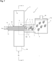
- Figs. 7 to 10 will be used to describe a producing apparatus 1 which can be used to produce the powder.
- the producing apparatus 1 comprises a burner 2, a raw material supplying unit 3, a reaction tube 4, a collector 5, and a gas reservoir 6.
- the raw material supplying unit 3 comprises an outer tube 13 and a raw material distribution tube 14.
- the burner 2 is tubular in shape, and the raw material supplying unit 3 is arranged in the burner 2.
- Burner gas 2a is distributed between the burner 2 and the outer tube 13.
- the burner gas 2a is used to form a flame 7 at the tip of the burner 2 by ignition.
- the flame 7 creates a high temperature region of 1000°C or more.
- the burner gas 2a preferably contains a combustible gas such as propane, methane, acetylene, hydrogen, or nitrous oxide.
- a gas mixture of oxygen and propane gas can be used as the burner gas 2a.
- the temperature in the high temperature region is, for example, 1000 to 2000°C, and is particularly, for example, 1000, 1100, 1200, 1300, 1400, 1500, 1600, 1700, 1800, 1900, or 2000°C, and may be in the range between the two values exemplified herein.
- a raw material solution 14a for producing the powder is distributed in the raw material distribution tube 14.
- a solution containing a Ni compound and, if necessary, a compound of transition metals (e.g., Co, Fe) is used as the raw material solution 14a.
- the compounds include fatty acid metal salts (e.g., fatty acid Ni, fatty acid Co, fatty acid Fe).
- the carbon number of the fatty acid is, for example, 2 to 20, preferably 4 to 15, and even more preferably 6 to 12.
- Octylic acid is preferrable as the fatty acid.
- the fatty acid metal salt is preferably dissolved or dispersed in a non-aqueous solvent.
- the non-aqueous solvent include organic solvents represented by turpentine. If moisture is contained in the raw material solution 14a, the fatty acid metal salts may undergo hydrolysis and degrade.
- Mist gas 13a which is used to mist the raw material solution 14a, is distributed between the outer tube 13 and the raw material distribution tube 14.
- the mist gas 13a and the raw material solution 14a are jetted together from the tip of the raw material supplying unit 3, the raw material solution 14a is misted.
- the mist 14b of the raw material solution 14a is sprayed into the flame 7, and the fatty acid metal salt in the raw material solution 14a undergoes a thermal decompose reaction in the flame 7 to produce an oxide powder, which is an aggregate of oxide particles 9 having the chain parts structured by fusion bonding crystallites 8 of an oxide into a chain.
- the crystallites 8, the oxide particles 9, and the oxide powder undergo the reducing and surface oxidizing process to yield the primary particles 82, the fine particles 80, and the powder 70, respectively.
- the mist gas 13a is, in one example, oxygen.
- the reaction tube 4 is provided between the collector 5 and the gas reservoir 6.
- the flame 7 is formed in the reaction tube 4.
- the collector 5 is provided with a filter 5a and a gas discharging portion 5b. A negative pressure is applied to the gas discharging portion 5b. This generates a flow that flows towards the gas discharging portion 5b in the collector 5 and the reaction tube 4.
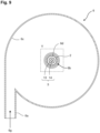
- the gas reservoir 6 is tubular in shape and comprises a cold gas introducing portion 6a and a slit 6b.
- a cold gas 6g is introduced into the gas reservoir 6 from the cold gas introducing portion 6a. Since the cold gas introducing portion 6a is oriented along the tangent line of the inner peripheral wall 6c of the gas reservoir 6, the cold gas 6g introduced into the gas reservoir 6 through the cold gas introducing portion 6a swirls along the inner peripheral wall 6c.
- a burner insertion hole 6d is provided in the center of the gas reservoir 6. The burner 2 is inserted through the burner insertion hole 6d.
- the slit 6b is provided at a position adjacent to the burner insertion hole 6d so as to surround the burner insertion hole 6d.
- the slit 6b is disposed to surround the burner 2.
- the cold gas 6g in the gas reservoir 6 is driven by the negative pressure applied to the gas discharging portion 5b and is discharged through the slit 6b toward the reaction tube 4.
- the cold gas 6g can be any gas capable of cooling the generated metal oxide, preferably an inert gas, e.g., air.
- the oxide particles 9 After the oxide particles 9 exit the flame 7, the oxide particles 9 are immediately cooled by the cold gas 6g, thus allowing to maintain the structure having the chain part.
- the cooled oxide particles 9 are captured and collected by the filter 5a.
- the captured oxide particles 9 may be subjected to heat treatment at 400 to 1000°C to adjust to the desired primary particle diameter.
- the oxide particles 9, which constitute the oxide powder obtained in the above step, are entirely oxide and have poor electrical conductivity. Therefore, in this step, after reducing the oxide particles 9 so that their entirety becomes metal, only the surface is oxidized to form the metal core part 90 and the oxide skin layer 91. Consequently, the electrode catalyst 50 structured with the powder 70, which is the aggregate of the fine particles 80 with the fused-aggregate network structure can be obtained.
- the reduction of the oxide particles 9 can be performed by heat treatment of the oxide particles 9 under a hydrogen-containing atmosphere.
- the hydrogen-containing atmosphere is an atmosphere containing hydrogen, preferably one in which the hydrogen is diluted with an inert gas (e.g., nitrogen).
- a hydrogen content in the atmosphere is, for example, 0.5 to 50 %.
- a heat treatment temperature is preferably 20 to 500 °C. This process reduces the oxide particles 9 to obtain the metal fine particles.
- the surface of the metal fine particles can be oxidized by holding them in nitrogen that contains trace amounts of oxygen during slow cooling to room temperature.
- a concentration of oxygen is preferably 0.5 to 50 ppm.
- the electrode catalysts were produced by the following method, and various evaluations were conducted.
- the electrode catalyst 50 was produced.
- gas prepared by blending 5 L/min of oxygen and 1 L/min of propane gas was used as the burner gas 2a. This gas was ignited to form the flame (chemical flame) 7 of 1600 °C or more at the tip of the burner 2.
- the raw material solution 14a was prepared by blending Ni octylate and Co octylate by a predetermined ratio, and then the blend was further combined with mineral spirit turpentine and dissolved.
- Ni octylate and Co octylate were blended so that the atomic ratio x of Co to the total of Ni and Co was 0, 0.2, 0.4, or 0.6 (Example 1, Example 2, Example 3, and Example 4, respectively).
- Oxygen was used as the mist gas 13a.
- 9 L/min of the mist gas 13a and 3 g/min of the raw material solution 14a were blended and sprayed from the tip of the raw material supplying unit 3, which is a spray nozzle (atomizer), towards the central part of the flame, thereby allowing combustion of the blend and generation of the oxide powder which is the aggregate of the particles 9.
- the raw material supplying unit 3 has a double-tube structure (overall length of 322.3 mm). Oxygen gas is supplied from the outer tube 13, and the raw material solution 14a is supplied to the raw material distribution tube 14. A fluid nozzle and an air nozzle were provided at the tip of the raw material distribution tube 14, and the raw material solution 14a was converted into mist 14b at the nozzles.
- the general formula of the oxide powder obtained is Ni 1-x Co x O.
- the reduction and surface oxidation were performed on the oxide powder obtained in the above process to form the metal core part 90 and the oxide skin layer 91.
- the electrode catalyst 50 structured with the powder 70 which is the aggregate of the fine particles 80 with the fused-aggregate network structure was obtained.
- the oxide particles 9 was reduced by heat treatment at 400°C for 2 hours in the hydrogen-containing atmosphere ( atmosphere of the gas mixture containing hydrogen and nitrogen, the hydrogen content of 1%.).
- the surface oxidation was performed by holding them in nitrogen that contains trace amounts of oxygen during slow cooling to room temperature after reduction.
- the concentration of oxygen was set at 5 ppm.
- Example 5 Ni 0.8 Mn 0.2 O
- Example 6 Ni 0.8 Fe 0.2 O
- the electrode catalysts 50 of Examples 5 to 6 were produced under the same condition as in Example 2, except that Mn octylate (Example 5) or Fe octylate (Example 6) was used instead of Co octylate.
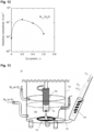
- the electrical conductivity of the electrode catalysts 50 of Examples 1 to 4 obtained by the above method was measured by the following method. The results are shown in Fig. 12 . As shown in Fig. 12 , the electrical conductivity was found to be particularly high, reaching 0.1 S/cm or more, when the Co content x is near 0.2.
- subject sample 8 samples of the electrode catalyst (hereinafter, "subject sample”) were weighed precisely using a precision electronic balance and were each filled into 8 sample folders (3 mm in diameter, 5 mm in depth) in a measurement jig.
- the measurement jig filled with the subject samples was set in a pressing device, and the subject samples were compressed with a force of 1.1 kN.
- the resistance of the subject samples was measured by the DC two-terminal method during powder compression, and the length of the subject samples during powder compression was also measured at the same time.
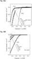
- the apparatus 15 comprises a glass cell 15a, a working electrode 15b, a counter electrode 15c, and a reference electrode 15d.
- the potential of the working electrode 15b relative to the reference electrode 15d can be adjusted by an unshown potentiostat.
- a KOH solution 15e with a concentration of 0.1 mol/L is contained in the glass cell 15a. Nitrogen or oxygen can be blown into the KOH solution 15e.
- the working electrode 15b is made of glassy carbon (GC) and is columnar in shape, and the electrode catalyst 50 is applied to its lower surface. The lower surface of the working electrode 15b and the counter electrode 15c are immersed in the KOH solution 15e.
- the reference electrode 15d is in a liquid junction with the KOH solution 15e through a salt bridge 15f.
- the electrode catalyst 50 in a state of being dispersed in a mixture of 80 wt% water and 20 wt% ethanol was applied to the lower surface of the working electrode 15b and then dried. Nitrogen was blown into the KOH solution 15e before the measurement to purge the KOH solution 15e. During the measurement, oxygen was blown in at a flow rate of 100 ml/min, and the reference electrode 15d was rotated around its central axis. Under these conditions, the current values were measured while changing the potential of the working electrode 15b relative to the reference electrode 15d (Potential /V vs RHE). The results are shown in Fig. 14A and Fig. 14B (Examples 1 to 4) and Fig.
- Fig. 14 A and Fig. 14B also show the results when the catalyst is the Pt/C (manufactured by Tanaka Kikinzoku Kogyo K.K., TEC10E50E), and is IrO x (manufactured by Tanaka Kikinzoku Kogyo K.K.).
- the electrode catalyst 50 was found to have a catalytic activity comparable to that of IrO x .
- the performance was also improved by adding Co and was particularly high when the Co content x was near 0.2.
- Fig. 16A and Fig. 16B Examples 1 to 4
- Fig. 17 Examples 1, 2, 5, and 6
- the electrode catalyst 50 was found to have excellent catalytic activity at the level intermediate between IrO x and Pt/C.
- the addition of Fe or Co significantly improved the performance, and the addition of Fe improved the performance particularly significantly.
- Co was added, the performance was particularly high when the Co content x was near 0.4.
- the anode catalyst was the electrode catalyst 50 (Ni 0.8 Co 0.2 O) of Example 2.
Landscapes
- Chemical & Material Sciences (AREA)
- Chemical Kinetics & Catalysis (AREA)
- Electrochemistry (AREA)
- Engineering & Computer Science (AREA)
- Materials Engineering (AREA)
- General Chemical & Material Sciences (AREA)
- Metallurgy (AREA)
- Organic Chemistry (AREA)
- Composite Materials (AREA)
- Inorganic Chemistry (AREA)
- Catalysts (AREA)
- Electrolytic Production Of Non-Metals, Compounds, Apparatuses Therefor (AREA)
Claims (7)
- Catalyseur d'électrode (50) sous la forme d'un matériau contenant des vides, dans lequel :le matériau contenant des vides est une poudre (70), qui est un agrégat de particules fines (80), le vide étant un espace (81) entre les particules fines (80) et un espace (84) à l'intérieur des particules fines (80) ;chacune des particules fines (80) comprend une partie centrale (90) et une couche de peau (91) recouvrant la partie centrale (90) ;la partie centrale (90) est structurée avec du métal ;la couche de peau (91) est structurée avec un oxyde contenant du Ni ; etles particules fines (80) agissent elles-mêmes comme un catalyseur,les particules fines (80) sont structurées avec une pluralité de particules primaires (82) liées par fusion pour former une chaîne (83).
- Catalyseur d'électrode (50) selon la revendication 1, dans lequel l'oxyde contient un métal de transition dont le numéro atomique est inférieur à celui du Ni.
- Catalyseur d'électrode (50) selon la revendication 2, dans lequel le métal de transition est le Co ou le Fe.
- Catalyseur d'électrode (50) selon l'une quelconque des revendications 1 à 3, dans lequel le corps contenant des vides présente un rapport de vides de 20 % ou plus.
- Cellule électrochimique à membrane échangeuse d'anions (10), comprenant une cathode (20), une anode (30) et une membrane échangeuse d'anions (40) disposées entre elles, dans laquelle au moins l'une des cathodes (20) et anodes (30) comprend une couche catalytique (23, 33) structurée avec le catalyseur d'électrode (50) selon l'une quelconque des revendications 1 à 4.
- Cellule électrochimique à membrane échangeuse d'anions (10) selon la revendication 5, dans laquelle la cellule électrochimique à membrane échangeuse d'anions (10) est une cellule d'électrolyse de l'eau.
- Cellule électrochimique à membrane échangeuse d'anions (10) selon la revendication 5, dans laquelle la cellule électrochimique à membrane échangeuse d'anions (10) est une pile à combustible.
Applications Claiming Priority (3)
| Application Number | Priority Date | Filing Date | Title |
|---|---|---|---|
| JP2020101517 | 2020-06-11 | ||
| JP2021045028 | 2021-03-18 | ||
| PCT/JP2021/021582 WO2021251341A1 (fr) | 2020-06-11 | 2021-06-07 | Catalyseur d'électrode et cellule électrochimique à membrane échangeuse d'anions |
Publications (3)
| Publication Number | Publication Date |
|---|---|
| EP4166692A1 EP4166692A1 (fr) | 2023-04-19 |
| EP4166692A4 EP4166692A4 (fr) | 2024-02-21 |
| EP4166692B1 true EP4166692B1 (fr) | 2024-09-11 |
Family
ID=78846276
Family Applications (1)
| Application Number | Title | Priority Date | Filing Date |
|---|---|---|---|
| EP21820086.3A Active EP4166692B1 (fr) | 2020-06-11 | 2021-06-07 | Catalyseur d'électrode et cellule électrochimique à membrane échangeuse d'anions |
Country Status (5)
| Country | Link |
|---|---|
| US (1) | US12548781B2 (fr) |
| EP (1) | EP4166692B1 (fr) |
| JP (1) | JP7730169B2 (fr) |
| CN (1) | CN115698386A (fr) |
| WO (1) | WO2021251341A1 (fr) |
Families Citing this family (7)
| Publication number | Priority date | Publication date | Assignee | Title |
|---|---|---|---|---|
| KR102679486B1 (ko) * | 2022-04-04 | 2024-07-01 | 국립금오공과대학교 산학협력단 | 음이온 교환막 수전해 장치 및 그의 제조방법 |
| JP2023177957A (ja) * | 2022-06-03 | 2023-12-14 | 三菱重工業株式会社 | 膜電極接合体、電解セル、電解装置、および膜電極接合体の製造方法 |
| WO2024143230A1 (fr) * | 2022-12-28 | 2024-07-04 | 国立大学法人山梨大学 | Catalyseur d'électrode et cellule électrochimique de type à membrane échangeuse d'anions |
| JP7664957B2 (ja) * | 2023-03-03 | 2025-04-18 | 三菱重工業株式会社 | 電解セルおよび電解装置 |
| WO2025183169A1 (fr) * | 2024-03-01 | 2025-09-04 | 国立大学法人東京科学大学 | Stratifié, assemblage membrane-électrode, dispositif d'électrolyse de l'eau et procédé de production de stratifié |
| WO2026063370A1 (fr) * | 2024-09-18 | 2026-03-26 | 国立大学法人山梨大学 | Catalyseur d'électrode et cellule électrochimique de type à membrane échangeuse d'anions |
| CN119736654A (zh) * | 2024-12-23 | 2025-04-01 | 上海交通大学 | 用于阴离子交换膜水电解制氢的气体扩散阴极及其制备和应用 |
Family Cites Families (20)
| Publication number | Priority date | Publication date | Assignee | Title |
|---|---|---|---|---|
| JP3940817B2 (ja) * | 2005-05-30 | 2007-07-04 | 松下電器産業株式会社 | デンドライト的構造を有するニッケル含有ナノ構造体を活性層に適用した電気化学電極及びその製造方法 |
| US20070092784A1 (en) | 2005-10-20 | 2007-04-26 | Dopp Robert B | Gas diffusion cathode using nanometer sized particles of transition metals for catalysis |
| US20080280190A1 (en) | 2005-10-20 | 2008-11-13 | Robert Brian Dopp | Electrochemical catalysts |
| WO2010035691A1 (fr) | 2008-09-24 | 2010-04-01 | 住友電気工業株式会社 | Réacteur électrochimique, procédé pour la fabrication du réacteur électrochimique, élément de décomposition de gaz, élément de décomposition d'ammoniac et groupe électrogène |
| JP2010201387A (ja) * | 2009-03-05 | 2010-09-16 | Sumitomo Electric Ind Ltd | ガス分解素子および発電装置 |
| WO2011065471A1 (fr) | 2009-11-27 | 2011-06-03 | 国立大学法人山梨大学 | Porteur de charge à haut potentiel stable à base d'oxyde destiné à une pile à combustible polymère solide |
| JP5648344B2 (ja) * | 2010-07-01 | 2015-01-07 | 住友電気工業株式会社 | 触媒、電極、燃料電池、ガス除害装置、並びに触媒および電極の製造方法 |
| KR101459403B1 (ko) | 2010-07-01 | 2014-11-07 | 스미토모덴키고교가부시키가이샤 | 막 전극 복합체, 연료 전지, 가스 제해 장치 및, 막 전극 복합체의 제조 방법 |
| DE102012200606A1 (de) * | 2012-01-17 | 2013-07-18 | Robert Bosch Gmbh | Elektrisch leitfähiges Material |
| KR102143571B1 (ko) * | 2013-07-02 | 2020-08-12 | 다이킨 고교 가부시키가이샤 | 전해질 용액 및 그 제조 방법, 연속 용해 장치, 전해질막, 전극 촉매층, 막 전극 접합체, 및 연료 전지 |
| AU2015289518B2 (en) | 2014-07-17 | 2019-09-26 | The Board Of Trustees Of The Leland Stanford Junior University | Heterostructures for ultra-active hydrogen evolution electrocatalysis |
| JP6581342B2 (ja) * | 2014-10-21 | 2019-09-25 | ダイハツ工業株式会社 | 燃料電池 |
| CN106999912B (zh) | 2014-12-25 | 2019-09-27 | 昭和电工株式会社 | 催化剂载体、其制造方法及其用途 |
| JP2019083085A (ja) * | 2016-03-17 | 2019-05-30 | 株式会社トクヤマ | 電極触媒層形成用ペースト及びその製造方法、並びに膜−電極触媒層接合体、ガス拡散電極、固体高分子型燃料電池及び固体高分子型水電解セルの製造方法 |
| WO2019021904A1 (fr) * | 2017-07-25 | 2019-01-31 | 国立大学法人山梨大学 | Poudre de support ainsi que procédé de fabrication de celle-ci, et catalyseur métallique sur support ainsi que procédé de fabrication de celle-ci |
| DK3763849T3 (da) | 2018-03-07 | 2022-12-12 | De Nora Permelec Ltd | Elektrolyseelektrode og fremgangsmåde til fremstilling af samme |
| CN108855184B (zh) | 2018-06-14 | 2020-03-13 | 中南大学 | 一种高性能析氧CoO@Co-NC/C复合催化剂及其制备方法和应用 |
| WO2020080400A1 (fr) * | 2018-10-19 | 2020-04-23 | 日本化学産業株式会社 | Catalyseur métallique sur support et son procédé de production |
| WO2020196236A1 (fr) * | 2019-03-27 | 2020-10-01 | 国立大学法人山梨大学 | Cellule d'électrolyse à oxyde solide, et procédé et système de fonctionnement de celle-ci |
| AU2023206867A1 (en) * | 2022-01-14 | 2024-06-27 | EvolOH, Inc. | Scalable electrode flow fields for water electrolyzers and method of high-speed manufacturing the same |
-
2021
- 2021-06-07 EP EP21820086.3A patent/EP4166692B1/fr active Active
- 2021-06-07 US US18/007,844 patent/US12548781B2/en active Active
- 2021-06-07 JP JP2022530555A patent/JP7730169B2/ja active Active
- 2021-06-07 WO PCT/JP2021/021582 patent/WO2021251341A1/fr not_active Ceased
- 2021-06-07 CN CN202180040419.8A patent/CN115698386A/zh active Pending
Also Published As
| Publication number | Publication date |
|---|---|
| US12548781B2 (en) | 2026-02-10 |
| EP4166692A4 (fr) | 2024-02-21 |
| EP4166692A1 (fr) | 2023-04-19 |
| CN115698386A (zh) | 2023-02-03 |
| WO2021251341A1 (fr) | 2021-12-16 |
| JPWO2021251341A1 (fr) | 2021-12-16 |
| US20230299307A1 (en) | 2023-09-21 |
| JP7730169B2 (ja) | 2025-08-27 |
Similar Documents
| Publication | Publication Date | Title |
|---|---|---|
| EP4166692B1 (fr) | Catalyseur d'électrode et cellule électrochimique à membrane échangeuse d'anions | |
| KR101864967B1 (ko) | 연료 전지용 전극 촉매 및 연료 전지용 전극 촉매의 제조 방법 | |
| Amin et al. | Electrocatalytic activity of nanostructured Ni and Pd–Ni on Vulcan XC-72R carbon black for methanol oxidation in alkaline medium | |
| JP6608800B2 (ja) | 燃料電池用電極触媒 | |
| EP2506350A1 (fr) | Porteur de charge à haut potentiel stable à base d'oxyde destiné à une pile à combustible polymère solide | |
| Rostami et al. | On the role of electrodeposited nanostructured Pd–Co alloy on Au for the electrocatalytic oxidation of glycerol in alkaline media | |
| CN102844465A (zh) | 核壳型金属纳米微粒及核壳型金属纳米微粒的制造方法 | |
| Habibi et al. | Carbon–ceramic supported bimetallic Pt–Ni nanoparticles as an electrocatalyst for oxidation of formic acid | |
| Pittayaporn et al. | Au/C catalysts promoted with Ni for glycerol electrooxidation in alkaline media | |
| Fu et al. | Enhanced electrocatalytic activities of three dimensional PtCu@ Pt bimetallic alloy nanofoams for oxygen reduction reaction | |
| Ribeiro et al. | Carbon-supported Pt and Pt–Ir nanowires for methanol electro-oxidation in acidic media | |
| KR101994088B1 (ko) | 팔라듐계 연료전지용 촉매의 제조방법 및 이에 의해 제조된 팔라듐계 연료전지용 촉매 | |
| JP2005005257A (ja) | 燃料電池用空気極触媒及びその製造方法 | |
| Asokan et al. | Insights Into the Effect of Nickel Doping on ZIF‐Derived Oxygen Reduction Catalysts for Zinc− Air Batteries | |
| KR20200085653A (ko) | 연료전지용 전극 촉매, 이의 제조방법 및 이를 구비하는 연료전지의 전극 구조물 | |
| Mahmoodi et al. | Novel electrocatalysts for borohydride fuel cells: enhanced power generation by optimizing anodic core–shell nanoparticles on reduced graphene oxide | |
| JP7678452B2 (ja) | 担持金属触媒、電気化学セル | |
| KR20230091951A (ko) | 연료 전지 전극 촉매 | |
| WO2024143230A1 (fr) | Catalyseur d'électrode et cellule électrochimique de type à membrane échangeuse d'anions | |
| JP5205434B2 (ja) | カソード触媒層、膜電極接合体、および燃料電池 | |
| US20230321633A1 (en) | Supported metal catalyst | |
| JP2009158253A (ja) | アルカリ型燃料電池用電極触媒及びアルカリ型燃料電池 | |
| JP2022114486A (ja) | 合金微粒子担持触媒の製造方法、電極、燃料電池、合金微粒子の製造方法、合金微粒子担持触媒、合金微粒子、膜電極接合体の製造方法、及び燃料電池の製造方法 | |
| Singh et al. | Solvothermal synthesis of Pt-Co/C cathode electrocatalyst for oxygen reduction reaction (ORR) in low temperature fuel cells. | |
| US20240055616A1 (en) | Supported metal catalyst |
Legal Events
| Date | Code | Title | Description |
|---|---|---|---|
| STAA | Information on the status of an ep patent application or granted ep patent |
Free format text: STATUS: THE INTERNATIONAL PUBLICATION HAS BEEN MADE |
|
| PUAI | Public reference made under article 153(3) epc to a published international application that has entered the european phase |
Free format text: ORIGINAL CODE: 0009012 |
|
| STAA | Information on the status of an ep patent application or granted ep patent |
Free format text: STATUS: REQUEST FOR EXAMINATION WAS MADE |
|
| 17P | Request for examination filed |
Effective date: 20221221 |
|
| AK | Designated contracting states |
Kind code of ref document: A1 Designated state(s): AL AT BE BG CH CY CZ DE DK EE ES FI FR GB GR HR HU IE IS IT LI LT LU LV MC MK MT NL NO PL PT RO RS SE SI SK SM TR |
|
| DAV | Request for validation of the european patent (deleted) | ||
| DAX | Request for extension of the european patent (deleted) | ||
| REG | Reference to a national code |
Ref country code: DE Ref legal event code: R079 Free format text: PREVIOUS MAIN CLASS: C25B0011091000 Ipc: C25B0001040000 Ref document number: 602021018776 Country of ref document: DE |
|
| A4 | Supplementary search report drawn up and despatched |
Effective date: 20240124 |
|
| RIC1 | Information provided on ipc code assigned before grant |
Ipc: H01M 4/90 20060101ALI20240118BHEP Ipc: C25B 11/077 20210101ALI20240118BHEP Ipc: C25B 11/061 20210101ALI20240118BHEP Ipc: C25B 11/031 20210101ALI20240118BHEP Ipc: C25B 11/03 20210101ALI20240118BHEP Ipc: C25B 9/23 20210101ALI20240118BHEP Ipc: C25B 1/04 20210101AFI20240118BHEP |
|
| GRAP | Despatch of communication of intention to grant a patent |
Free format text: ORIGINAL CODE: EPIDOSNIGR1 |
|
| STAA | Information on the status of an ep patent application or granted ep patent |
Free format text: STATUS: GRANT OF PATENT IS INTENDED |
|
| RIC1 | Information provided on ipc code assigned before grant |
Ipc: H01M 4/90 20060101ALI20240523BHEP Ipc: C25B 11/077 20210101ALI20240523BHEP Ipc: C25B 11/061 20210101ALI20240523BHEP Ipc: C25B 11/031 20210101ALI20240523BHEP Ipc: C25B 11/03 20210101ALI20240523BHEP Ipc: C25B 9/23 20210101ALI20240523BHEP Ipc: C25B 1/04 20210101AFI20240523BHEP |
|
| INTG | Intention to grant announced |
Effective date: 20240619 |
|
| GRAS | Grant fee paid |
Free format text: ORIGINAL CODE: EPIDOSNIGR3 |
|
| GRAA | (expected) grant |
Free format text: ORIGINAL CODE: 0009210 |
|
| STAA | Information on the status of an ep patent application or granted ep patent |
Free format text: STATUS: THE PATENT HAS BEEN GRANTED |
|
| AK | Designated contracting states |
Kind code of ref document: B1 Designated state(s): AL AT BE BG CH CY CZ DE DK EE ES FI FR GB GR HR HU IE IS IT LI LT LU LV MC MK MT NL NO PL PT RO RS SE SI SK SM TR |
|
| REG | Reference to a national code |
Ref country code: GB Ref legal event code: FG4D |
|
| REG | Reference to a national code |
Ref country code: CH Ref legal event code: EP |
|
| REG | Reference to a national code |
Ref country code: DE Ref legal event code: R096 Ref document number: 602021018776 Country of ref document: DE |
|
| P01 | Opt-out of the competence of the unified patent court (upc) registered |
Free format text: CASE NUMBER: APP_49325/2024 Effective date: 20240830 |
|
| REG | Reference to a national code |
Ref country code: IE Ref legal event code: FG4D |
|
| REG | Reference to a national code |
Ref country code: LT Ref legal event code: MG9D |
|
| PG25 | Lapsed in a contracting state [announced via postgrant information from national office to epo] |
Ref country code: NO Free format text: LAPSE BECAUSE OF FAILURE TO SUBMIT A TRANSLATION OF THE DESCRIPTION OR TO PAY THE FEE WITHIN THE PRESCRIBED TIME-LIMIT Effective date: 20241211 |
|
| REG | Reference to a national code |
Ref country code: NL Ref legal event code: MP Effective date: 20240911 |
|
| PG25 | Lapsed in a contracting state [announced via postgrant information from national office to epo] |
Ref country code: GR Free format text: LAPSE BECAUSE OF FAILURE TO SUBMIT A TRANSLATION OF THE DESCRIPTION OR TO PAY THE FEE WITHIN THE PRESCRIBED TIME-LIMIT Effective date: 20241212 Ref country code: FI Free format text: LAPSE BECAUSE OF FAILURE TO SUBMIT A TRANSLATION OF THE DESCRIPTION OR TO PAY THE FEE WITHIN THE PRESCRIBED TIME-LIMIT Effective date: 20240911 |
|
| PG25 | Lapsed in a contracting state [announced via postgrant information from national office to epo] |
Ref country code: BG Free format text: LAPSE BECAUSE OF FAILURE TO SUBMIT A TRANSLATION OF THE DESCRIPTION OR TO PAY THE FEE WITHIN THE PRESCRIBED TIME-LIMIT Effective date: 20240911 |
|
| PG25 | Lapsed in a contracting state [announced via postgrant information from national office to epo] |
Ref country code: LV Free format text: LAPSE BECAUSE OF FAILURE TO SUBMIT A TRANSLATION OF THE DESCRIPTION OR TO PAY THE FEE WITHIN THE PRESCRIBED TIME-LIMIT Effective date: 20240911 |
|
| PG25 | Lapsed in a contracting state [announced via postgrant information from national office to epo] |
Ref country code: HR Free format text: LAPSE BECAUSE OF FAILURE TO SUBMIT A TRANSLATION OF THE DESCRIPTION OR TO PAY THE FEE WITHIN THE PRESCRIBED TIME-LIMIT Effective date: 20240911 |
|
| PG25 | Lapsed in a contracting state [announced via postgrant information from national office to epo] |
Ref country code: ES Free format text: LAPSE BECAUSE OF FAILURE TO SUBMIT A TRANSLATION OF THE DESCRIPTION OR TO PAY THE FEE WITHIN THE PRESCRIBED TIME-LIMIT Effective date: 20240911 Ref country code: RS Free format text: LAPSE BECAUSE OF FAILURE TO SUBMIT A TRANSLATION OF THE DESCRIPTION OR TO PAY THE FEE WITHIN THE PRESCRIBED TIME-LIMIT Effective date: 20241211 |
|
| PG25 | Lapsed in a contracting state [announced via postgrant information from national office to epo] |
Ref country code: RS Free format text: LAPSE BECAUSE OF FAILURE TO SUBMIT A TRANSLATION OF THE DESCRIPTION OR TO PAY THE FEE WITHIN THE PRESCRIBED TIME-LIMIT Effective date: 20241211 Ref country code: NO Free format text: LAPSE BECAUSE OF FAILURE TO SUBMIT A TRANSLATION OF THE DESCRIPTION OR TO PAY THE FEE WITHIN THE PRESCRIBED TIME-LIMIT Effective date: 20241211 Ref country code: LV Free format text: LAPSE BECAUSE OF FAILURE TO SUBMIT A TRANSLATION OF THE DESCRIPTION OR TO PAY THE FEE WITHIN THE PRESCRIBED TIME-LIMIT Effective date: 20240911 Ref country code: HR Free format text: LAPSE BECAUSE OF FAILURE TO SUBMIT A TRANSLATION OF THE DESCRIPTION OR TO PAY THE FEE WITHIN THE PRESCRIBED TIME-LIMIT Effective date: 20240911 Ref country code: GR Free format text: LAPSE BECAUSE OF FAILURE TO SUBMIT A TRANSLATION OF THE DESCRIPTION OR TO PAY THE FEE WITHIN THE PRESCRIBED TIME-LIMIT Effective date: 20241212 Ref country code: FI Free format text: LAPSE BECAUSE OF FAILURE TO SUBMIT A TRANSLATION OF THE DESCRIPTION OR TO PAY THE FEE WITHIN THE PRESCRIBED TIME-LIMIT Effective date: 20240911 Ref country code: ES Free format text: LAPSE BECAUSE OF FAILURE TO SUBMIT A TRANSLATION OF THE DESCRIPTION OR TO PAY THE FEE WITHIN THE PRESCRIBED TIME-LIMIT Effective date: 20240911 Ref country code: BG Free format text: LAPSE BECAUSE OF FAILURE TO SUBMIT A TRANSLATION OF THE DESCRIPTION OR TO PAY THE FEE WITHIN THE PRESCRIBED TIME-LIMIT Effective date: 20240911 |
|
| REG | Reference to a national code |
Ref country code: AT Ref legal event code: MK05 Ref document number: 1722739 Country of ref document: AT Kind code of ref document: T Effective date: 20240911 |
|
| PG25 | Lapsed in a contracting state [announced via postgrant information from national office to epo] |
Ref country code: NL Free format text: LAPSE BECAUSE OF FAILURE TO SUBMIT A TRANSLATION OF THE DESCRIPTION OR TO PAY THE FEE WITHIN THE PRESCRIBED TIME-LIMIT Effective date: 20240911 |
|
| PG25 | Lapsed in a contracting state [announced via postgrant information from national office to epo] |
Ref country code: IS Free format text: LAPSE BECAUSE OF FAILURE TO SUBMIT A TRANSLATION OF THE DESCRIPTION OR TO PAY THE FEE WITHIN THE PRESCRIBED TIME-LIMIT Effective date: 20250111 Ref country code: PT Free format text: LAPSE BECAUSE OF FAILURE TO SUBMIT A TRANSLATION OF THE DESCRIPTION OR TO PAY THE FEE WITHIN THE PRESCRIBED TIME-LIMIT Effective date: 20250113 |
|
| PG25 | Lapsed in a contracting state [announced via postgrant information from national office to epo] |
Ref country code: RO Free format text: LAPSE BECAUSE OF FAILURE TO SUBMIT A TRANSLATION OF THE DESCRIPTION OR TO PAY THE FEE WITHIN THE PRESCRIBED TIME-LIMIT Effective date: 20240911 Ref country code: SM Free format text: LAPSE BECAUSE OF FAILURE TO SUBMIT A TRANSLATION OF THE DESCRIPTION OR TO PAY THE FEE WITHIN THE PRESCRIBED TIME-LIMIT Effective date: 20240911 |
|
| PG25 | Lapsed in a contracting state [announced via postgrant information from national office to epo] |
Ref country code: AT Free format text: LAPSE BECAUSE OF FAILURE TO SUBMIT A TRANSLATION OF THE DESCRIPTION OR TO PAY THE FEE WITHIN THE PRESCRIBED TIME-LIMIT Effective date: 20240911 Ref country code: EE Free format text: LAPSE BECAUSE OF FAILURE TO SUBMIT A TRANSLATION OF THE DESCRIPTION OR TO PAY THE FEE WITHIN THE PRESCRIBED TIME-LIMIT Effective date: 20240911 |
|
| PG25 | Lapsed in a contracting state [announced via postgrant information from national office to epo] |
Ref country code: PL Free format text: LAPSE BECAUSE OF FAILURE TO SUBMIT A TRANSLATION OF THE DESCRIPTION OR TO PAY THE FEE WITHIN THE PRESCRIBED TIME-LIMIT Effective date: 20240911 Ref country code: CZ Free format text: LAPSE BECAUSE OF FAILURE TO SUBMIT A TRANSLATION OF THE DESCRIPTION OR TO PAY THE FEE WITHIN THE PRESCRIBED TIME-LIMIT Effective date: 20240911 |
|
| PG25 | Lapsed in a contracting state [announced via postgrant information from national office to epo] |
Ref country code: IT Free format text: LAPSE BECAUSE OF FAILURE TO SUBMIT A TRANSLATION OF THE DESCRIPTION OR TO PAY THE FEE WITHIN THE PRESCRIBED TIME-LIMIT Effective date: 20240911 Ref country code: SK Free format text: LAPSE BECAUSE OF FAILURE TO SUBMIT A TRANSLATION OF THE DESCRIPTION OR TO PAY THE FEE WITHIN THE PRESCRIBED TIME-LIMIT Effective date: 20240911 |
|
| REG | Reference to a national code |
Ref country code: DE Ref legal event code: R097 Ref document number: 602021018776 Country of ref document: DE |
|
| PGFP | Annual fee paid to national office [announced via postgrant information from national office to epo] |
Ref country code: DE Payment date: 20250429 Year of fee payment: 5 |
|
| PG25 | Lapsed in a contracting state [announced via postgrant information from national office to epo] |
Ref country code: DK Free format text: LAPSE BECAUSE OF FAILURE TO SUBMIT A TRANSLATION OF THE DESCRIPTION OR TO PAY THE FEE WITHIN THE PRESCRIBED TIME-LIMIT Effective date: 20240911 |
|
| PLBE | No opposition filed within time limit |
Free format text: ORIGINAL CODE: 0009261 |
|
| STAA | Information on the status of an ep patent application or granted ep patent |
Free format text: STATUS: NO OPPOSITION FILED WITHIN TIME LIMIT |
|
| 26N | No opposition filed |
Effective date: 20250612 |
|
| PG25 | Lapsed in a contracting state [announced via postgrant information from national office to epo] |
Ref country code: SE Free format text: LAPSE BECAUSE OF FAILURE TO SUBMIT A TRANSLATION OF THE DESCRIPTION OR TO PAY THE FEE WITHIN THE PRESCRIBED TIME-LIMIT Effective date: 20240911 |
|
| REG | Reference to a national code |
Ref country code: CH Ref legal event code: H13 Free format text: ST27 STATUS EVENT CODE: U-0-0-H10-H13 (AS PROVIDED BY THE NATIONAL OFFICE) Effective date: 20260127 |
|
| PG25 | Lapsed in a contracting state [announced via postgrant information from national office to epo] |
Ref country code: MC Free format text: LAPSE BECAUSE OF FAILURE TO SUBMIT A TRANSLATION OF THE DESCRIPTION OR TO PAY THE FEE WITHIN THE PRESCRIBED TIME-LIMIT Effective date: 20240911 |
|
| PG25 | Lapsed in a contracting state [announced via postgrant information from national office to epo] |
Ref country code: LU Free format text: LAPSE BECAUSE OF NON-PAYMENT OF DUE FEES Effective date: 20250607 |
|
| GBPC | Gb: european patent ceased through non-payment of renewal fee |
Effective date: 20250607 |
|
| REG | Reference to a national code |
Ref country code: BE Ref legal event code: MM Effective date: 20250630 |
|
| PG25 | Lapsed in a contracting state [announced via postgrant information from national office to epo] |
Ref country code: GB Free format text: LAPSE BECAUSE OF NON-PAYMENT OF DUE FEES Effective date: 20250607 |
|
| PG25 | Lapsed in a contracting state [announced via postgrant information from national office to epo] |
Ref country code: IE Free format text: LAPSE BECAUSE OF NON-PAYMENT OF DUE FEES Effective date: 20250607 |
|
| PG25 | Lapsed in a contracting state [announced via postgrant information from national office to epo] |
Ref country code: BE Free format text: LAPSE BECAUSE OF NON-PAYMENT OF DUE FEES Effective date: 20250630 |
|
| PG25 | Lapsed in a contracting state [announced via postgrant information from national office to epo] |
Ref country code: FR Free format text: LAPSE BECAUSE OF NON-PAYMENT OF DUE FEES Effective date: 20250630 |
|
| PG25 | Lapsed in a contracting state [announced via postgrant information from national office to epo] |
Ref country code: CH Free format text: LAPSE BECAUSE OF NON-PAYMENT OF DUE FEES Effective date: 20250630 |