EP4166745B1 - Rollladen-/raffstore-kasten - Google Patents
Rollladen-/raffstore-kasten Download PDFInfo
- Publication number
- EP4166745B1 EP4166745B1 EP22201240.3A EP22201240A EP4166745B1 EP 4166745 B1 EP4166745 B1 EP 4166745B1 EP 22201240 A EP22201240 A EP 22201240A EP 4166745 B1 EP4166745 B1 EP 4166745B1
- Authority
- EP
- European Patent Office
- Prior art keywords
- roller shutter
- leg
- venetian blind
- free end
- base body
- Prior art date
- Legal status (The legal status is an assumption and is not a legal conclusion. Google has not performed a legal analysis and makes no representation as to the accuracy of the status listed.)
- Active
Links
Images




Classifications
-
- E—FIXED CONSTRUCTIONS
- E06—DOORS, WINDOWS, SHUTTERS, OR ROLLER BLINDS IN GENERAL; LADDERS
- E06B—FIXED OR MOVABLE CLOSURES FOR OPENINGS IN BUILDINGS, VEHICLES, FENCES OR LIKE ENCLOSURES IN GENERAL, e.g. DOORS, WINDOWS, BLINDS, GATES
- E06B9/00—Screening or protective devices for wall or similar openings, with or without operating or securing mechanisms; Closures of similar construction
- E06B9/02—Shutters, movable grilles, or other safety closing devices, e.g. against burglary
- E06B9/08—Roll-type closures
- E06B9/11—Roller shutters
- E06B9/17—Parts or details of roller shutters, e.g. suspension devices, shutter boxes, wicket doors, ventilation openings
- E06B9/17007—Shutter boxes; Details or component parts thereof
-
- E—FIXED CONSTRUCTIONS
- E06—DOORS, WINDOWS, SHUTTERS, OR ROLLER BLINDS IN GENERAL; LADDERS
- E06B—FIXED OR MOVABLE CLOSURES FOR OPENINGS IN BUILDINGS, VEHICLES, FENCES OR LIKE ENCLOSURES IN GENERAL, e.g. DOORS, WINDOWS, BLINDS, GATES
- E06B9/00—Screening or protective devices for wall or similar openings, with or without operating or securing mechanisms; Closures of similar construction
- E06B9/02—Shutters, movable grilles, or other safety closing devices, e.g. against burglary
- E06B9/08—Roll-type closures
- E06B9/11—Roller shutters
- E06B9/17—Parts or details of roller shutters, e.g. suspension devices, shutter boxes, wicket doors, ventilation openings
- E06B9/17007—Shutter boxes; Details or component parts thereof
- E06B9/17015—Shutter boxes; Details or component parts thereof made of at most two pieces; Front opening details
-
- E—FIXED CONSTRUCTIONS
- E06—DOORS, WINDOWS, SHUTTERS, OR ROLLER BLINDS IN GENERAL; LADDERS
- E06B—FIXED OR MOVABLE CLOSURES FOR OPENINGS IN BUILDINGS, VEHICLES, FENCES OR LIKE ENCLOSURES IN GENERAL, e.g. DOORS, WINDOWS, BLINDS, GATES
- E06B9/00—Screening or protective devices for wall or similar openings, with or without operating or securing mechanisms; Closures of similar construction
- E06B9/24—Screens or other constructions affording protection against light, especially against sunshine; Similar screens for privacy or appearance; Slat blinds
- E06B9/26—Lamellar or like blinds, e.g. venetian blinds
- E06B9/28—Lamellar or like blinds, e.g. venetian blinds with horizontal lamellae, e.g. non-liftable
- E06B9/30—Lamellar or like blinds, e.g. venetian blinds with horizontal lamellae, e.g. non-liftable liftable
- E06B9/32—Operating, guiding, or securing devices therefor
- E06B9/323—Structure or support of upper box
-
- E—FIXED CONSTRUCTIONS
- E06—DOORS, WINDOWS, SHUTTERS, OR ROLLER BLINDS IN GENERAL; LADDERS
- E06B—FIXED OR MOVABLE CLOSURES FOR OPENINGS IN BUILDINGS, VEHICLES, FENCES OR LIKE ENCLOSURES IN GENERAL, e.g. DOORS, WINDOWS, BLINDS, GATES
- E06B9/00—Screening or protective devices for wall or similar openings, with or without operating or securing mechanisms; Closures of similar construction
- E06B9/02—Shutters, movable grilles, or other safety closing devices, e.g. against burglary
- E06B9/08—Roll-type closures
- E06B9/11—Roller shutters
- E06B9/17—Parts or details of roller shutters, e.g. suspension devices, shutter boxes, wicket doors, ventilation openings
- E06B2009/17069—Insulation
Definitions
- the present invention relates generally to devices for receiving roller shutters or venetian blinds and the like.
- roller shutter/Venetian blind boxes that are integrated into the building's outer wall above a window or door are well known. It is also known to equip such roller shutter/Venetian blind boxes with a decentralized room ventilation system that can transport air from the inside of the building through the roller shutter/Venetian blind box to the outside and vice versa.
- the document EN 20 2020 005414 U1 shows a roller shutter/Venetian blind box according to the preamble of claim 1.
- the present invention provides a roller shutter/venetian blind box according to the independent claim. Embodiments and variants thereof are specified in the dependent claims.
- the invention relates to a roller shutter/Venetian blind box for accommodating a roller shutter or Venetian blind, comprising a base body which provides a roller shutter/Venetian blind space for arranging the roller shutter or Venetian blind and an air duct.
- the roller shutter/Venetian blind box can have an insulating crescent that separates the roller shutter/Venetian blind space and the air duct.
- the use of an insulating crescent is intended in particular for designs in which the roller shutter/Venetian blind box is used for roller shutters.
- An insulating crescent can also be used for Venetian blinds. However, designs without an insulating crescent are also possible for Venetian blinds.
- the base body comprises a first leg with a free end.
- the roller shutter/venetian blind box comprises an air guide element which is arranged on an inner side of the first leg and is in fluid communication with the air duct, wherein the air guide element is designed to guide air from the air duct into the roller shutter/venetian blind space Air from the roller shutter/venetian blind area can also be directed into the air duct via the air guide element.
- the air guiding element can be arranged detachably.
- a force-fitting, form-fitting, clamping, locking, snap-in, screw or adhesive connection(s) or combinations thereof can be used.
- the air guiding element can be arranged on the inner side of the first leg at a distance from the free end of the first leg.
- the first leg tapers from its free end in the direction of the air guide element. This can be understood in particular to mean that the width of the first leg at or adjacent to the free end is greater than the width of the first leg in a region remote therefrom, preferably in the region of the air guide element.
- the tapering of the first leg can be achieved by a corresponding design of its inner side, whereas an outer side of the first leg is designed in such a way that it does not contribute to the tapering.
- the insulating crescent can be supported with a first end on the inside of the first leg and/or the air guide element.
- the support can be detachable.
- a force-fitting, form-fitting, clamping, locking, snap-on, screw or adhesive connection(s) or combinations thereof can be used to support the insulating crescent.
- the insulation crescent can be supported with a second end on a stop formed in or on the base body.
- the support can be detachable.
- a force-fitting, form-fitting, clamping, locking, snap-on, screw or adhesive connection(s) or combinations thereof can be used to support the insulation crescent.
- the stop can, for example, be formed on an inner side of the base body, which limits the roller shutter/venetian blind space.
- the stop can be a recess in the base body.
- the base body may have a second leg with a free end.
- An insulating wedge may be provided which is arranged at the free end of the second leg.
- the insulating wedge can comprise a part extending away from the free end of the second leg, which determines the size of an opening that extends between a free end of the insulating wedge and the free end of the first leg.
- the curtain of a roller shutter or slats of a Venetian blind can be moved through this opening.
- the opening can have a width in the range of 50-150 millimeters, preferably in the range of 70-90 millimeters or 130-150 millimeters.
- the base body may have an inspection opening extending between the free end of the first leg and the free end of the second leg.
- the inspection opening can have a width in the range of 180-230 millimetres
- the roller shutter/Venetian blind box can have an installation height in the range of 300-350 millimeters, preferably in the range of 330 millimeters.
- the roller shutter/venetian blind space can comprise a hollow cylindrical space, the cross section of which has a radius transverse to the longitudinal axis in the range of 80-110 millimeters, preferably in the range of 105 millimeters.
- the arrangement of the roller shutter or venetian blind can have a cross section with respect to its longitudinal axis, the cutting surface of which has an inner circle radius in the range of mm.
- a filler piece can be provided in the roller shutter/venetian blind space, which partially fills the roller shutter/venetian blind space.
- Fig.1 shows schematically a roller shutter/venetian blind box 2 which is installed above a window 4 in an external building wall 6.
- the roller shutter/venetian blind box 2 can also be arranged below or on any other side of the window. Furthermore, the roller shutter/venetian blind box 2 can also be used for a door or another type of wall opening in an external wall 6 of a building.
- the roller shutter/venetian blind box 2 is integrated into the building wall 6, preferably in such a way that the outside of the roller shutter/venetian blind box 2 or the plaster and/or insulation applied to it are essentially in the same plane as the building's outer wall 6, thus creating a continuous surface.
- the roller shutter/venetian blind box 2 can at least partially protrude outwards from the building's outer wall 6 or be attached to the outside of it.
- roller shutter/venetian blind box 2 is cuboid-shaped with a length L and a height H as well as a Fig.2 specified width B.
- the roller shutter/Venetian blind box 2 can be shaped so that it can be used, for example, for a window or door whose glare and/or sash is curved at the top, or for a window or door used in conjunction with an arched lintel.
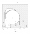
- Fig.2 shows a cross-section of the roller shutter/venetian blind box 2 along section AA of Fig.1 .
- the embodiment in Fig.2 comprises a base body 8, an air guiding element 10, an insulating crescent 12, an air duct 14 and a roller shutter/venetian blind space 16.
- the base body 8 is preferably manufactured using one or more materials with good thermal and preferably also acoustic insulation properties.
- materials include, for example, EPS, XPS, NEOPOR, as well as all types of polystyrene.
- the base body 8 comprises a first leg 18, which is formed by the part of the base body 8 which, with reference to the drawings, begins slightly above a first end 12a of the insulating crescent 12 and extends downwards from there.
- the first leg 18 has a free end 20.
- the free end 20 has a substantially planar end surface which extends substantially in the direction of the width B.
- the end surface of the free end 20 extends in a direction which encloses an angle with the width B.
- the end surface of the free end 20 can be substantially planar and extend obliquely from bottom right to top left or top right to bottom left with respect to the plane of the drawing.
- the free end 20 can have an end surface which is curved in the plane formed by the height H and the width B.
- the end surface can be U-shaped in order to be able to accommodate, for example, a sealing element and/or cabling or a fastening for a plaster rail which is explained in more detail below.
- the first leg 18 has a smaller width (i.e. cross-section in the direction of width B) at its upper end as shown, i.e. the free end 20, than at its free end 20.
- this is achieved on the inner side 22 of the first leg 18 by the inner side 22 extending from a location 22a where the first leg 18 has a first width to a location 22b where the first leg 18 has a second width that is smaller than the second width.
- the inner side 22 is essentially flat and extends - in the cross-section shown - in a straight line between the point 22a and the point 22b.
- the inner side 22 can be curved, for example in such a way that it is concave or convex in plan view (i.e. when looking at the inner side 22 in the direction of the width B as shown).
- the point 22a is spaced from the free end 20, the width of the leg between the point 22a and the free end 20 being essentially constant.
- the first leg 18 can be made more stable and/or stiffer in the area of its free end 20.
- This variant can also make it easier to attach further components to the first leg 18 at and/or adjacent to the free end 20.
- the location 22A is located at the free end 20. In this way, the space created by reducing the width of the first leg 18 in the direction of the air guide element 10 can be increased.
- the outer side 24 of the first leg 18 forms part of the outer side 26 of the base body 8, which, when used as intended, forms part of the outer surface of the building wall 6. This ensures that the building wall 6 has a substantially continuous surface on the outside.
- the air guiding element 10 is arranged on the inner side 22 of the first leg 18 at a distance from the free end of the first leg 18.
- the air guiding element 10 can be attached there by means of a force-fitting, form-fitting, clamping, locking, snap-on, screw or adhesive connection or a combination of two or more such connections.
- the air guiding element 10 provides a fluid connection, in particular for air, between the air duct 14 and the roller shutter/venetian blind space 16.
- the air duct 14 can be connected to a so-called decentralized living space ventilation system (not shown), which has a fan (or other means) for conveying air from the interior of the building to the outside, e.g. to remove warmer air from the interior of the building for interior cooling and to supply colder air from the outside to the interior of the building and/or to remove colder air from the interior of the building and to supply warmer air from the outside to the interior of the building for interior heating.
- a fan or other means for conveying air from the interior of the building to the outside, e.g. to remove warmer air from the interior of the building for interior cooling and to supply colder air from the outside to the interior of the building and/or to remove colder air from the interior of the building and to supply warmer air from the outside to the interior of the building for interior heating.
- the fan can be used to transport air from the air duct 14 through the air guide element 10 into the roller shutter/venetian blind room 16. In this way, air can be removed from the interior of the building. Conversely, it is possible to use the fan to transport air from the roller shutter/venetian blind room 16 through the air guide element 10 into the air duct 14, allowing outside air to reach the interior of the building.
- the air guiding element 10 is designed as a double-wall plate.
- a double-wall plate comprises two essentially parallel plates which are connected by webs extending perpendicularly to them.
- a double-wall plate thus provides channels which are rectangular in cross section.
- the air guiding element 10 can have one or more channels provided in another way (which can, for example, be round in cross section).
- the insulating crescent 12 separates the air duct 14 and the roller shutter/venetian blind space 16, preferably in such a way that a fluid connection between the air duct 14 and the roller shutter/venetian blind space 16 only exists via the air guide element 10.
- the insulating crescent 12 interacts with the first end 12a and the inner side 22 of the first leg 18 above the air guiding element 10 and/or the air guiding element 10.
- the first end 12a of the insulating crescent 12 can be attached to the inner side 22 of the first leg 18 above the air guiding element 10 and/or to the air guiding element 10 by means of a force-fitting, form-fitting, clamping, locking, snap-on, screw or adhesive connection or a combination of two or more such connections.
- the first end 12a of the insulating crescent has a shoulder 12c, by means of which the insulating crescent is supported on the inner side 22 of the first leg 18 above the air guiding element 10 and on the air guiding element 10.
- the support can be designed to be detachable.
- the base body 8 has an inner side 28 which has a substantially circular segment-shaped cross-section and, when roller shutters are used, forms part of the boundary of the roller shutter/venetian blind space 16. At the upper end of the inner side 28 as shown, a stop 30 is formed in the base body 8.
- the insulating crescent 12 interacts with the stop 30 formed on the inner side 28 of the base body 8.
- the second end 12b of the insulating crescent 12 can interact with the stop 28 by means of a force-fitting, form-fitting, clamping, locking, snap-on, screw or adhesive connection or a combination of two or more such connections.
- the insulating crescent 12 has an inner side 12d which has a substantially circular segment-shaped cross-section and forms part of the boundary of the roller shutter/venetian blind space 16.
- the insulating crescent 12, the stop 28 and the inner side 28 of the base body 8 are shaped and/or arranged such that the inner side 12d of the insulating crescent 12 and the inner side 28 of the base body 8 form a substantially uninterrupted surface (apart from the area where the two inner sides adjoin one another), in particular such that the cross section of this surface also has a substantially circular segment-shaped cross section.
- the insulating crescent 12 can be firmly connected to the base body 8 and, if necessary, the air guiding element 10.
- the insulating crescent 12 in a detachable manner.
- this can be achieved by an insulating crescent 12 made of an at least partially elastic material, which allows the insulating crescent 12 to be supported, latched or the like at the first end 12a by means of its shoulder 12c on the inner side 22 of the first leg above the air guiding element 10 and/or the air guiding element 10 and the second end 12b of the insulating crescent 12 on the stop 30 of the base body 8.
- the base body 8 has a second leg 32.
- the second leg 32 of the base body has an inner side 32a and an outer side 32b, as well as a free end 32c.
- the inner side 32a of the second leg 32 adjoins the inner side 28 of the base body and can have a step 32d.
- the inner side 34 of the base body 8 i.e. the side of the base body which forms part of the inner surface of the building wall 6 when the roller shutter/venetian blind box 2 is used as intended, comprises the inner side 32b of the second leg 32. This ensures that the building wall 6 also has a substantially continuous surface on the outside.
- the free end 32c of the second leg 32 may have a protruding structure 36.
- the inspection opening 38 is an opening through which the roller shutter/venetian blind space 16 can be accessed, for example to install/remove a roller shutter or to maintain it.
- Fig.3 illustrates embodiments in which a plaster rail 40 already mentioned above and an insulating wedge 42 are present, which can be used when using the roller shutter/venetian blind box 2 for roller shutters.
- the plaster rail 40 can serve as a plaster finishing profile for a plaster applied to the outside of the first leg 18. Likewise or additionally, the plaster rail 40 can be designed as a drip edge.
- the insulating wedge 42 has a fastening area 42a, a free end 42b, an inner side 42c delimiting the roller shutter/venetian blind space 16, and a lower side 42d.
- the fastening area 42a serves for the preferably detachable connection (e.g. by means of screws) of the insulation wedge 42 to the second leg 32 of the base body 8.
- the fastening region 42a is designed such that it has surfaces which are complementary to the inner side 32a and the free end 32c of the second leg 32 of the base body 8.
- the part of the insulating wedge 42 between the free end 42b of the insulating wedge 42 and the surface of the fastening area 42a that is complementary to the inner side 32a of the second leg 32 of the base body 8 has a length LD.
- the length LD determines the size of an outlet opening 44 of the roller shutter/venetian blind box 2.
- the outlet opening 44 extends between the free end 20 of the first leg 18 of the base body 8 and the free end 44b of the insulating wedge 42.
- the outlet opening 44 is the opening through which a roller shutter can be lowered and pulled up.
- the inner side 42c of the insulating wedge 42 has a circular segment-shaped cross-section.
- the circular segment-shaped cross-sections of the inner side 12d of the insulating crescent 12, the inner side 28 of the base body 8 and the inner side 42c of the insulating wedge are circular segments with a common center point M.
- these inner sides, considered together, have a circular segment-shaped cross-section that lies on a circle around the center point M.
- Fig.4 illustrates embodiments in which a plaster rail 40 and an insulating wedge 42 are also used, whereby the insulating wedge 42 is intended here for use with the roller shutter/venetian blind box 2 for venetian blinds.
- the above statements apply to Fig.3 for the Fig.4 accordingly, unless expressly stated otherwise.
- the outlet opening 44 of Fig.4 is the opening through which a venetian blind can be lowered and pulled up.
- a filler piece 46 can be provided.
- the filler piece 46 can fill the part of the roller shutter/Venetian blind space 16 that is not required for Venetian blinds.
- the present invention may further have the following features and advantages.
- the air guide element can have a length in the range of 30 to 90, preferably 60 millimeters. This means that an air guide element can be used that is significantly shorter than previously known air guide elements. This reduces "flow losses" when air is transported through the air guide element.
- the height H of the roller shutter/venetian blind box also known as the installation height, can be in the range of 300 to 350, preferably 330 millimeters. This makes it possible to provide roller shutter/venetian blind boxes with installation heights that can simplify the integration of a roller shutter/venetian blind box into predefined brickwork grids (e.g. standard grids). The use of door and window frames with standard dimensions is also supported.
- the width B of the roller shutter/venetian blind box also known as the installation width, can be in the range of 250 to 490 millimeters.
- the roller shutter/venetian blind box can be installed flush on the inside and outside of the building's exterior wall.
- a brick box 48 is used for the base body 8, which has a substantially U-shaped cross-section transverse to the longitudinal axis with respect to the longitudinal axis L.
- the brick box 48 can be referred to as a "housing”.
- the filling material 50 is arranged in the brick box 48.
- the filling material 50 can comprise, for example, EPS, XPS, NEOPOR, as well as all types of polystyrene, as well as mixtures or combinations of two or more such materials.
- the filling material 50 is designed in such a way that the brick box 48 and the filling material 50, considered together, result in a cross section transverse to the longitudinal axis which corresponds to the cross section of the base body of Fig.2 corresponds to, or at least is comparable with, the features described as usable in the invention. Therefore, unless otherwise stated below, reference is made to the above statements, which also apply here without repetition.
- the first leg 18 of the base body 8 is provided by the left leg of the brick box 48 as shown.
- the second leg 32 of the base body 8 is provided by the right leg of the brick box 48 as shown and the filling material arranged there.
- the stop 30 of the base body 8 is formed in the filling material 50.
- the base body 8 comprising the brick box 48 and the filling material 50 can also, as explained above, be used with an insulating wedge 42, which allows the accommodation and use of a roller shutter or a Venetian blind.
- Fig.5 which refer to the use of the base body 8 comprising the brick box 48 and the filling material 50 with an insulating wedge 42 for roller shutters.
- Fig.3 apply here accordingly.
- Fig.4 apply here accordingly if the base body 8 comprising the brick box 48 and the filling material 50 is used with an insulating wedge 42 for Venetian blinds.
Landscapes
- Engineering & Computer Science (AREA)
- Structural Engineering (AREA)
- Architecture (AREA)
- Civil Engineering (AREA)
- Blinds (AREA)
Applications Claiming Priority (1)
| Application Number | Priority Date | Filing Date | Title |
|---|---|---|---|
| DE102021126526.6A DE102021126526A1 (de) | 2021-10-13 | 2021-10-13 | Rollladen-/Raffstore-Kasten |
Publications (3)
| Publication Number | Publication Date |
|---|---|
| EP4166745A1 EP4166745A1 (de) | 2023-04-19 |
| EP4166745C0 EP4166745C0 (de) | 2024-08-14 |
| EP4166745B1 true EP4166745B1 (de) | 2024-08-14 |
Family
ID=83691190
Family Applications (1)
| Application Number | Title | Priority Date | Filing Date |
|---|---|---|---|
| EP22201240.3A Active EP4166745B1 (de) | 2021-10-13 | 2022-10-13 | Rollladen-/raffstore-kasten |
Country Status (3)
| Country | Link |
|---|---|
| EP (1) | EP4166745B1 (pl) |
| DE (1) | DE102021126526A1 (pl) |
| PL (1) | PL4166745T3 (pl) |
Family Cites Families (4)
| Publication number | Priority date | Publication date | Assignee | Title |
|---|---|---|---|---|
| DE8102063U1 (de) | 1981-01-28 | 1981-07-16 | Ingenieur Klaus Blaurock Bau- und Raumtechnik, 8741 Salz | Rolladen |
| DE19654704A1 (de) | 1996-12-30 | 1998-07-02 | Walter Foeckersperger | Raumbelüftungsverfahren |
| DE102017112908A1 (de) | 2017-06-12 | 2018-01-11 | Duotherm Rolladen Gmbh | Rollladenkasten oder Raffstorekasten |
| DE202020005414U1 (de) * | 2020-01-28 | 2021-02-19 | impruf GmbH | Rollladenkasten-Anordnung zur Verwendung in einem System zur dezentralen Wohnraumlüftung |
-
2021
- 2021-10-13 DE DE102021126526.6A patent/DE102021126526A1/de active Pending
-
2022
- 2022-10-13 EP EP22201240.3A patent/EP4166745B1/de active Active
- 2022-10-13 PL PL22201240.3T patent/PL4166745T3/pl unknown
Also Published As
| Publication number | Publication date |
|---|---|
| EP4166745A1 (de) | 2023-04-19 |
| PL4166745T3 (pl) | 2025-01-20 |
| DE102021126526A1 (de) | 2023-04-13 |
| EP4166745C0 (de) | 2024-08-14 |
Similar Documents
| Publication | Publication Date | Title |
|---|---|---|
| EP2594725B1 (de) | Fenster | |
| EP2348187B1 (de) | Rollladenkasten | |
| EP2850272B1 (de) | Rahmenlueftungsgeraet, fensteranordnung und eingebautes fenster mit lüftungsgeraet zum lueften und zum erhalt der regulaeren verglasungsgroesse und auch rahmenabmessungen | |
| EP0658662B1 (de) | Glasfassade mit Fenster | |
| DE3101551C2 (de) | Türzarge | |
| EP2780529B1 (de) | Lueftungsgeraet fuer den profilierten blendrahmen eines fluegels und luft-austauschverfahren am fenster | |
| EP4166745B1 (de) | Rollladen-/raffstore-kasten | |
| EP2354431B1 (de) | Rollladenkasten mit Lamellenführungsteilen | |
| CH620026A5 (en) | Device intended for installation in the region of a window for the forced ventilation of rooms | |
| DE202021004338U1 (de) | Rollladen-/Raffstore-Kasten | |
| EP2843179A1 (de) | Rollladenkastenbaugruppe, sowie Kastenwandprofil und Zusatzprofil dafür | |
| EP0479234A1 (de) | Seitensektionaltor, Deckensektionaltor oder Rundlauftor | |
| EP2907961A2 (de) | Modularer Rollladenkasten | |
| EP0180163A2 (de) | Flügel für Klappläden, Haus- und Zimmertüren und Schranktüren mit Jalousieteil | |
| EP3299534B1 (de) | Dachfenster | |
| EP4198248B1 (de) | Bordstück eines rollladenkastens | |
| EP1260669B1 (de) | Rolladenaufsatzkasten | |
| EP4102021B1 (de) | Fenster- oder tür-hohlkammerprofil, system mit einem solchen hohlkammerprofil und daraus hergestellter rahmen | |
| DE202017104941U1 (de) | Seitenteil für einen Aufnahmekasten zum Einbau in Fenster- oder Türöffnungen und Aufnahmekasten zum Einbau in Fenster- oder Türöffnungen mit einem solchen Seitenteil | |
| EP0723063A1 (de) | Vorrichtung zum Befestigen einer Türschwelle am Blendrahmen einer nach aussen öffnenden Türe | |
| EP2369118B1 (de) | Rollladenkasten sowie Isolationsteil für einen Rollladenkasten | |
| DE202010016979U1 (de) | Lichtband und Hallenwand mit einem Lichtband | |
| DE102010064687B3 (de) | Verfahren zur Herstellung eines Rollladenkastens | |
| EP4411098A1 (de) | Verglasungseinheit mit einem funktionselement und verfahren zu dessen herstellung | |
| DE9016617U1 (de) | Hebeschiebetür |
Legal Events
| Date | Code | Title | Description |
|---|---|---|---|
| PUAI | Public reference made under article 153(3) epc to a published international application that has entered the european phase |
Free format text: ORIGINAL CODE: 0009012 |
|
| STAA | Information on the status of an ep patent application or granted ep patent |
Free format text: STATUS: THE APPLICATION HAS BEEN PUBLISHED |
|
| AK | Designated contracting states |
Kind code of ref document: A1 Designated state(s): AL AT BE BG CH CY CZ DE DK EE ES FI FR GB GR HR HU IE IS IT LI LT LU LV MC ME MK MT NL NO PL PT RO RS SE SI SK SM TR |
|
| STAA | Information on the status of an ep patent application or granted ep patent |
Free format text: STATUS: REQUEST FOR EXAMINATION WAS MADE |
|
| 17P | Request for examination filed |
Effective date: 20231016 |
|
| RBV | Designated contracting states (corrected) |
Designated state(s): AL AT BE BG CH CY CZ DE DK EE ES FI FR GB GR HR HU IE IS IT LI LT LU LV MC ME MK MT NL NO PL PT RO RS SE SI SK SM TR |
|
| GRAP | Despatch of communication of intention to grant a patent |
Free format text: ORIGINAL CODE: EPIDOSNIGR1 |
|
| STAA | Information on the status of an ep patent application or granted ep patent |
Free format text: STATUS: GRANT OF PATENT IS INTENDED |
|
| INTG | Intention to grant announced |
Effective date: 20231222 |
|
| GRAS | Grant fee paid |
Free format text: ORIGINAL CODE: EPIDOSNIGR3 |
|
| GRAJ | Information related to disapproval of communication of intention to grant by the applicant or resumption of examination proceedings by the epo deleted |
Free format text: ORIGINAL CODE: EPIDOSDIGR1 |
|
| GRAL | Information related to payment of fee for publishing/printing deleted |
Free format text: ORIGINAL CODE: EPIDOSDIGR3 |
|
| STAA | Information on the status of an ep patent application or granted ep patent |
Free format text: STATUS: REQUEST FOR EXAMINATION WAS MADE |
|
| GRAP | Despatch of communication of intention to grant a patent |
Free format text: ORIGINAL CODE: EPIDOSNIGR1 |
|
| STAA | Information on the status of an ep patent application or granted ep patent |
Free format text: STATUS: GRANT OF PATENT IS INTENDED |
|
| INTC | Intention to grant announced (deleted) | ||
| INTG | Intention to grant announced |
Effective date: 20240506 |
|
| GRAA | (expected) grant |
Free format text: ORIGINAL CODE: 0009210 |
|
| STAA | Information on the status of an ep patent application or granted ep patent |
Free format text: STATUS: THE PATENT HAS BEEN GRANTED |
|
| AK | Designated contracting states |
Kind code of ref document: B1 Designated state(s): AL AT BE BG CH CY CZ DE DK EE ES FI FR GB GR HR HU IE IS IT LI LT LU LV MC ME MK MT NL NO PL PT RO RS SE SI SK SM TR |
|
| REG | Reference to a national code |
Ref country code: GB Ref legal event code: FG4D Free format text: NOT ENGLISH |
|
| REG | Reference to a national code |
Ref country code: CH Ref legal event code: EP |
|
| REG | Reference to a national code |
Ref country code: DE Ref legal event code: R096 Ref document number: 502022001456 Country of ref document: DE |
|
| REG | Reference to a national code |
Ref country code: IE Ref legal event code: FG4D Free format text: LANGUAGE OF EP DOCUMENT: GERMAN |
|
| U01 | Request for unitary effect filed |
Effective date: 20240814 |
|
| U07 | Unitary effect registered |
Designated state(s): AT BE BG DE DK EE FI FR IT LT LU LV MT NL PT SE SI Effective date: 20240827 |
|
| U20 | Renewal fee for the european patent with unitary effect paid |
Year of fee payment: 3 Effective date: 20241108 |
|
| PG25 | Lapsed in a contracting state [announced via postgrant information from national office to epo] |
Ref country code: NO Free format text: LAPSE BECAUSE OF FAILURE TO SUBMIT A TRANSLATION OF THE DESCRIPTION OR TO PAY THE FEE WITHIN THE PRESCRIBED TIME-LIMIT Effective date: 20241114 |
|
| PG25 | Lapsed in a contracting state [announced via postgrant information from national office to epo] |
Ref country code: IS Free format text: LAPSE BECAUSE OF FAILURE TO SUBMIT A TRANSLATION OF THE DESCRIPTION OR TO PAY THE FEE WITHIN THE PRESCRIBED TIME-LIMIT Effective date: 20241214 |
|
| PG25 | Lapsed in a contracting state [announced via postgrant information from national office to epo] |
Ref country code: HR Free format text: LAPSE BECAUSE OF FAILURE TO SUBMIT A TRANSLATION OF THE DESCRIPTION OR TO PAY THE FEE WITHIN THE PRESCRIBED TIME-LIMIT Effective date: 20240814 |
|
| PG25 | Lapsed in a contracting state [announced via postgrant information from national office to epo] |
Ref country code: ES Free format text: LAPSE BECAUSE OF FAILURE TO SUBMIT A TRANSLATION OF THE DESCRIPTION OR TO PAY THE FEE WITHIN THE PRESCRIBED TIME-LIMIT Effective date: 20240814 Ref country code: RS Free format text: LAPSE BECAUSE OF FAILURE TO SUBMIT A TRANSLATION OF THE DESCRIPTION OR TO PAY THE FEE WITHIN THE PRESCRIBED TIME-LIMIT Effective date: 20241114 |
|
| PG25 | Lapsed in a contracting state [announced via postgrant information from national office to epo] |
Ref country code: RS Free format text: LAPSE BECAUSE OF FAILURE TO SUBMIT A TRANSLATION OF THE DESCRIPTION OR TO PAY THE FEE WITHIN THE PRESCRIBED TIME-LIMIT Effective date: 20241114 Ref country code: NO Free format text: LAPSE BECAUSE OF FAILURE TO SUBMIT A TRANSLATION OF THE DESCRIPTION OR TO PAY THE FEE WITHIN THE PRESCRIBED TIME-LIMIT Effective date: 20241114 Ref country code: IS Free format text: LAPSE BECAUSE OF FAILURE TO SUBMIT A TRANSLATION OF THE DESCRIPTION OR TO PAY THE FEE WITHIN THE PRESCRIBED TIME-LIMIT Effective date: 20241214 Ref country code: HR Free format text: LAPSE BECAUSE OF FAILURE TO SUBMIT A TRANSLATION OF THE DESCRIPTION OR TO PAY THE FEE WITHIN THE PRESCRIBED TIME-LIMIT Effective date: 20240814 Ref country code: ES Free format text: LAPSE BECAUSE OF FAILURE TO SUBMIT A TRANSLATION OF THE DESCRIPTION OR TO PAY THE FEE WITHIN THE PRESCRIBED TIME-LIMIT Effective date: 20240814 |
|
| PG25 | Lapsed in a contracting state [announced via postgrant information from national office to epo] |
Ref country code: SM Free format text: LAPSE BECAUSE OF FAILURE TO SUBMIT A TRANSLATION OF THE DESCRIPTION OR TO PAY THE FEE WITHIN THE PRESCRIBED TIME-LIMIT Effective date: 20240814 |
|
| PG25 | Lapsed in a contracting state [announced via postgrant information from national office to epo] |
Ref country code: CZ Free format text: LAPSE BECAUSE OF FAILURE TO SUBMIT A TRANSLATION OF THE DESCRIPTION OR TO PAY THE FEE WITHIN THE PRESCRIBED TIME-LIMIT Effective date: 20240814 |
|
| PG25 | Lapsed in a contracting state [announced via postgrant information from national office to epo] |
Ref country code: SK Free format text: LAPSE BECAUSE OF FAILURE TO SUBMIT A TRANSLATION OF THE DESCRIPTION OR TO PAY THE FEE WITHIN THE PRESCRIBED TIME-LIMIT Effective date: 20240814 |
|
| PLBE | No opposition filed within time limit |
Free format text: ORIGINAL CODE: 0009261 |
|
| STAA | Information on the status of an ep patent application or granted ep patent |
Free format text: STATUS: NO OPPOSITION FILED WITHIN TIME LIMIT |
|
| PG25 | Lapsed in a contracting state [announced via postgrant information from national office to epo] |
Ref country code: MC Free format text: LAPSE BECAUSE OF FAILURE TO SUBMIT A TRANSLATION OF THE DESCRIPTION OR TO PAY THE FEE WITHIN THE PRESCRIBED TIME-LIMIT Effective date: 20240814 |
|
| 26N | No opposition filed |
Effective date: 20250515 |
|
| PG25 | Lapsed in a contracting state [announced via postgrant information from national office to epo] |
Ref country code: IE Free format text: LAPSE BECAUSE OF NON-PAYMENT OF DUE FEES Effective date: 20241013 |
|
| REG | Reference to a national code |
Ref country code: CH Ref legal event code: U11 Free format text: ST27 STATUS EVENT CODE: U-0-0-U10-U11 (AS PROVIDED BY THE NATIONAL OFFICE) Effective date: 20251101 |
|
| PG25 | Lapsed in a contracting state [announced via postgrant information from national office to epo] |
Ref country code: RO Free format text: LAPSE BECAUSE OF FAILURE TO SUBMIT A TRANSLATION OF THE DESCRIPTION OR TO PAY THE FEE WITHIN THE PRESCRIBED TIME-LIMIT Effective date: 20240814 |
|
| U20 | Renewal fee for the european patent with unitary effect paid |
Year of fee payment: 4 Effective date: 20251027 |
|
| PGFP | Annual fee paid to national office [announced via postgrant information from national office to epo] |
Ref country code: CH Payment date: 20251101 Year of fee payment: 4 |
|
| PGFP | Annual fee paid to national office [announced via postgrant information from national office to epo] |
Ref country code: PL Payment date: 20251002 Year of fee payment: 4 |
|
| PG25 | Lapsed in a contracting state [announced via postgrant information from national office to epo] |
Ref country code: CY Free format text: LAPSE BECAUSE OF FAILURE TO SUBMIT A TRANSLATION OF THE DESCRIPTION OR TO PAY THE FEE WITHIN THE PRESCRIBED TIME-LIMIT; INVALID AB INITIO Effective date: 20221013 |
|
| PG25 | Lapsed in a contracting state [announced via postgrant information from national office to epo] |
Ref country code: HU Free format text: LAPSE BECAUSE OF FAILURE TO SUBMIT A TRANSLATION OF THE DESCRIPTION OR TO PAY THE FEE WITHIN THE PRESCRIBED TIME-LIMIT; INVALID AB INITIO Effective date: 20221013 |