EP4166836B1 - Schnellkupplung und verbindungsanordnung mit einer solchen schnellkupplung - Google Patents
Schnellkupplung und verbindungsanordnung mit einer solchen schnellkupplung Download PDFInfo
- Publication number
- EP4166836B1 EP4166836B1 EP22201166.0A EP22201166A EP4166836B1 EP 4166836 B1 EP4166836 B1 EP 4166836B1 EP 22201166 A EP22201166 A EP 22201166A EP 4166836 B1 EP4166836 B1 EP 4166836B1
- Authority
- EP
- European Patent Office
- Prior art keywords
- seal
- longitudinal axis
- male
- quick coupling
- diameter
- Prior art date
- Legal status (The legal status is an assumption and is not a legal conclusion. Google has not performed a legal analysis and makes no representation as to the accuracy of the status listed.)
- Active
Links
Images



Classifications
-
- F—MECHANICAL ENGINEERING; LIGHTING; HEATING; WEAPONS; BLASTING
- F16—ENGINEERING ELEMENTS AND UNITS; GENERAL MEASURES FOR PRODUCING AND MAINTAINING EFFECTIVE FUNCTIONING OF MACHINES OR INSTALLATIONS; THERMAL INSULATION IN GENERAL
- F16L—PIPES; JOINTS OR FITTINGS FOR PIPES; SUPPORTS FOR PIPES, CABLES OR PROTECTIVE TUBING; MEANS FOR THERMAL INSULATION IN GENERAL
- F16L37/00—Couplings of the quick-acting type
- F16L37/28—Couplings of the quick-acting type with fluid cut-off means
- F16L37/38—Couplings of the quick-acting type with fluid cut-off means with fluid cut-off means in only one of two pipe-end fittings
- F16L37/44—Couplings of the quick-acting type with fluid cut-off means with fluid cut-off means in only one of two pipe-end fittings with one lift valve being actuated to initiate the flow through the coupling after the two coupling parts are locked against withdrawal
-
- F—MECHANICAL ENGINEERING; LIGHTING; HEATING; WEAPONS; BLASTING
- F16—ENGINEERING ELEMENTS AND UNITS; GENERAL MEASURES FOR PRODUCING AND MAINTAINING EFFECTIVE FUNCTIONING OF MACHINES OR INSTALLATIONS; THERMAL INSULATION IN GENERAL
- F16L—PIPES; JOINTS OR FITTINGS FOR PIPES; SUPPORTS FOR PIPES, CABLES OR PROTECTIVE TUBING; MEANS FOR THERMAL INSULATION IN GENERAL
- F16L37/00—Couplings of the quick-acting type
- F16L37/28—Couplings of the quick-acting type with fluid cut-off means
- F16L37/30—Couplings of the quick-acting type with fluid cut-off means with fluid cut-off means in each of two pipe-end fittings
- F16L37/32—Couplings of the quick-acting type with fluid cut-off means with fluid cut-off means in each of two pipe-end fittings at least one of two lift valves being opened automatically when the coupling is applied
- F16L37/34—Couplings of the quick-acting type with fluid cut-off means with fluid cut-off means in each of two pipe-end fittings at least one of two lift valves being opened automatically when the coupling is applied at least one of the lift valves being of the sleeve type, i.e. a sleeve being telescoped over an inner cylindrical wall
-
- F—MECHANICAL ENGINEERING; LIGHTING; HEATING; WEAPONS; BLASTING
- F16—ENGINEERING ELEMENTS AND UNITS; GENERAL MEASURES FOR PRODUCING AND MAINTAINING EFFECTIVE FUNCTIONING OF MACHINES OR INSTALLATIONS; THERMAL INSULATION IN GENERAL
- F16L—PIPES; JOINTS OR FITTINGS FOR PIPES; SUPPORTS FOR PIPES, CABLES OR PROTECTIVE TUBING; MEANS FOR THERMAL INSULATION IN GENERAL
- F16L33/00—Arrangements for connecting hoses to rigid members; Rigid hose-connectors, i.e. single members engaging both hoses
-
- F—MECHANICAL ENGINEERING; LIGHTING; HEATING; WEAPONS; BLASTING
- F16—ENGINEERING ELEMENTS AND UNITS; GENERAL MEASURES FOR PRODUCING AND MAINTAINING EFFECTIVE FUNCTIONING OF MACHINES OR INSTALLATIONS; THERMAL INSULATION IN GENERAL
- F16L—PIPES; JOINTS OR FITTINGS FOR PIPES; SUPPORTS FOR PIPES, CABLES OR PROTECTIVE TUBING; MEANS FOR THERMAL INSULATION IN GENERAL
- F16L37/00—Couplings of the quick-acting type
- F16L37/08—Couplings of the quick-acting type in which the connection between abutting or axially overlapping ends is maintained by locking members
- F16L37/084—Couplings of the quick-acting type in which the connection between abutting or axially overlapping ends is maintained by locking members combined with automatic locking
-
- F—MECHANICAL ENGINEERING; LIGHTING; HEATING; WEAPONS; BLASTING
- F16—ENGINEERING ELEMENTS AND UNITS; GENERAL MEASURES FOR PRODUCING AND MAINTAINING EFFECTIVE FUNCTIONING OF MACHINES OR INSTALLATIONS; THERMAL INSULATION IN GENERAL
- F16L—PIPES; JOINTS OR FITTINGS FOR PIPES; SUPPORTS FOR PIPES, CABLES OR PROTECTIVE TUBING; MEANS FOR THERMAL INSULATION IN GENERAL
- F16L37/00—Couplings of the quick-acting type
- F16L37/08—Couplings of the quick-acting type in which the connection between abutting or axially overlapping ends is maintained by locking members
- F16L37/084—Couplings of the quick-acting type in which the connection between abutting or axially overlapping ends is maintained by locking members combined with automatic locking
- F16L37/098—Couplings of the quick-acting type in which the connection between abutting or axially overlapping ends is maintained by locking members combined with automatic locking by means of flexible hooks
-
- F—MECHANICAL ENGINEERING; LIGHTING; HEATING; WEAPONS; BLASTING
- F16—ENGINEERING ELEMENTS AND UNITS; GENERAL MEASURES FOR PRODUCING AND MAINTAINING EFFECTIVE FUNCTIONING OF MACHINES OR INSTALLATIONS; THERMAL INSULATION IN GENERAL
- F16L—PIPES; JOINTS OR FITTINGS FOR PIPES; SUPPORTS FOR PIPES, CABLES OR PROTECTIVE TUBING; MEANS FOR THERMAL INSULATION IN GENERAL
- F16L37/00—Couplings of the quick-acting type
- F16L37/28—Couplings of the quick-acting type with fluid cut-off means
- F16L37/30—Couplings of the quick-acting type with fluid cut-off means with fluid cut-off means in each of two pipe-end fittings
- F16L37/32—Couplings of the quick-acting type with fluid cut-off means with fluid cut-off means in each of two pipe-end fittings at least one of two lift valves being opened automatically when the coupling is applied
- F16L37/35—Couplings of the quick-acting type with fluid cut-off means with fluid cut-off means in each of two pipe-end fittings at least one of two lift valves being opened automatically when the coupling is applied at least one of the valves having an axial bore communicating with lateral apertures
Definitions
- connection assembly The advantages induced by this connection assembly are similar to those induced by the quick connector of the invention.
- the male element 4 is mounted on a connection plate 8 partially shown and on which can, in practice, be mounted several other male or female connection elements not shown.
- connection plate 10 is movable, in the sense that it can be brought closer to the connection plate 8 which is fixed, according to a translation movement represented by the arrow F10 and generally parallel to the fitting axis X2, to the coupling of elements 4 and 6, that is to say the closing of the quick connector 2.
- the movable connection plate 10 is moved away from the fixed connection plate 8 according to a movement of opposite translation to that of arrow F10.
- Connection plates 8 and 10 and connection 2 belong to connection assembly 1, as well as any other connection elements mounted on these connection plates.
- the male element 4 comprises a male tubular body 42 which extends along a longitudinal axis X4 of the male element 4, between a proximal or rear end 422 and a distal or front end 424.
- the proximal end 422 is open and arranged opposite the outlet of pipe 12 in bore 14.
- the male tubular body 42 also comprises an annular flange 426 which surrounds a tubular portion of the body 42 and which extends outwards, radially to the longitudinal axis X4, at a distance from each of the ends 422 and 424 along the longitudinal axis X4. Between the collar 426 and the end 424, the tubular body 422 is cylindrical with a constant circular section, with an external diameter ⁇ 42 and an internal diameter ⁇ 42, less than the diameter ⁇ 42 of twice the thickness of the male tubular body 42. Note S42 the internal radial surface of the male tubular body which has a diameter ⁇ 42.
- the collar 426 is arranged in a countersink 82 of the connection plate 8 which surrounds the distal mouth of the bore 14 and which is of a diameter strictly greater than that of the collar 426.
- a seal 43 is interposed between a rear face of the collar 426 and the bottom of the counterbore 82.
- a threaded flange 84 is screwed into a thread 86 of the counterbore 82 and has an L-shaped section which allows it to retain, axially along the axis X4, the collar 426 in the countersink 82.
- Means not shown make it possible to immobilize the flange 84 in rotation relative to the connection plate 8.
- the flange 84 provides space for radial translation to the flange 426 to improve the positioning of the axis X2 relative to the axis X6.
- the positioning of the male tubular body 42 can be adjusted relative to the connection plate 8 according to a movement in a plane radial to the longitudinal axis X4. This makes it possible to align the male element 4 and the female element 6 during coupling or uncoupling, by making the axes X4 and X6 coincide.
- the distal end 424 of the male tubular body 42 is closed by a valve 46 movable in translation inside the male tubular body 42, along the longitudinal axis X4, between an advanced position and a rearward position. In its advanced position, the valve 46 closes a distal mouth 428 of the male element 4, which is defined by the distal end 424 and whose diameter is noted as ⁇ 428.
- the male tubular body 42 On an internal face of its distal end 424, the male tubular body 42 has an internal peripheral groove 423.
- This groove 423 is defined, along the longitudinal axis X4, between an internal rib 425 of the distal end 424 and a annular wall 427 which tightens the distal end 424 at the level of the mouth 428.
- the volume V42 is defined, along the longitudinal axis X4, behind the groove 423.
- the seal 48 is shown outside the male tubular body 42 which shows its geometry without constraint, that is to say when it is not compressed between the elements 42 and 46.
- the seal 48 can be firmly held in place in the groove 423, by cooperation of shapes, or even by means of a slight compression of the heel 482 in the groove 423.
- the internal diameter ⁇ 486 of the seal 48 is the diameter of the surface S486 and has a variable value along the surface S486, between a maximum value, in the vicinity of the front surface S48, and a minimum value, at the level of the bead 486 when it is not constrained.
- the value of this axial offset ⁇ 4 is between 0.3 and 0.7 mm, preferably between 0.4 and 0.6 mm, more preferably l order of 0.5 mm.
- the front surface S48 When the valve 46 is in the advanced configuration, the front surface S48 is set back, along the longitudinal axis therefore perpendicular to the longitudinal axis X4, and containing the front face 462.
- the front surface S468 In the advanced configuration of the valve 46, the front surface S468 is located, along the longitudinal axis X6, between the planes P4 and ⁇ 4.
- d4 the distance, measured parallel to the axis X4, between the planes P4 and ⁇ 4, when the valve 46 is in the advanced position.
- the seal 48 occupies the volume V428.
- the female tubular body also includes an annular extra thickness 626, in other words an external flange, provided with a peripheral and external groove in which an O-ring 63 is received.
- the extra thickness 626 is configured to be positioned in an enlarged mouth of the bore 18, the seal 63 then bearing against the peripheral surface of this bore.
- the female tubular body 62 is provided with a thread 621 which cooperates with a tapping 181 of the bore 18, such that that the female tubular body 62 is screwed into the bore 18 in the vicinity of the proximal end 622.
- the longitudinal axis X6 is thus fixed relative to the connection plate 10 and aligned with the fitting axis X2.
- the female tubular body houses a pusher 64 which extends along the longitudinal axis X6 between the distal end 624 and a base 71 secured to the female tubular body 62 in the vicinity of its proximal end 622, by means of an elastic rod 72.
- the pusher 64 has a head 644 which has a front face 642, in the shape of a disc centered on the longitudinal axis X6, and a cylindrical peripheral surface external S644, also centered on this axis.
- the front face 642 has the same section as the front face 462.
- the female tubular body 62 has, in the vicinity of its distal end 624, a frustoconical internal surface 625, centered on the axis X6 and converging towards the bearing surfaces S624A and S624B. We note 629 a junction edge between the surfaces S624B and 625.
- a distal mouth 628 of the female element 6 is intended to be closed by the head 644 associated with a drawer 66 movable in translation inside the female tubular body 66, along the longitudinal axis X6, between an advanced position where it closes the mouth 628 of the female element 6 and a retracted or rear position where it does not block this second mouth.
- ⁇ 628 as the diameter of the mouth 628.
- the diameter ⁇ 628 is strictly less than the diameter ⁇ 62.
- the drawer 62 is formed of two annular parts 66A and 66B fitted one inside the other and which respectively constitute a front part and a rear part of the drawer 66.
- front and rear parts of the valve are fitted onto each other.
- other methods can be used to bring the front and rear parts together, for example screwing or crimping.
- the front part 66A of the drawer 66 defines a frustoconical surface S66A converging towards the front in the direction of the axis progress of it.
- the front part 66A comprises, on its internal side facing the head 644, an internal peripheral groove 663 of shape comparable to the groove 423 and of which we denote F663 the bottom, S663 a front edge surface and S'663 an edge surface back.
- the groove 663 is defined, along the longitudinal axis of the distal end of the drawer 66 which defines the front face 662 of the drawer 66.
- the frontal or front surface S667 of the rib 667 which is opposite the groove 663 and the volume V62, constitutes part of the face before 662.
- the edge 669 delimits the junction between the front face 662 of the drawer 66 and an internal radial surface of the rib 667, which surrounds the mouth 628.
- This internal radial surface of the rib 667 also surrounds a volume V628 defined, analogously to the volume V428, as an annular volume which extends, radially to the longitudinal axis X6, between the annular wall 667 and the external radial surface S644 of the head 644, around the pusher 64, at the level of the mouth 628, when the drawer 66 is in the advanced position.
- P6 an edge plane of the female element 6, defined as a plane radial to the longitudinal axis X6 and passing through the edge 669.
- the edge plane P6 includes the surfaces 662 and S667.
- the edge plane P6 passes through the edge 629 when the drawer is in the advanced position.
- the front part 66A defines, on the other hand, a volume V66 of annular shape and open towards the rear, radially outwards relative to the axis X6.
- a second seal 68 is mounted in the groove 663 and extends inside the front part 66A of the drawer 66.
- the seal 68 also extends around the surface S644 of the head 644 of the pusher 64, as visible at the figure 1 and in the upper and middle parts of the Figure 3 . In this position, the seal 68 rests on the wall S644, in a direction radial to the axis X6.
- the seal 68 is shown outside the female tubular body 62 to show its geometry without constraint, that is to say when it is not compressed between the elements 62 and 66.
- the section of the seal 68 is full and constant around the axis X6. It occupies volume V628.
- the seal 68 comprises a heel 682, for hooking into the groove 663, a central part 684 and a bead 686 arranged, relative to the central part and radially to the longitudinal axis X6, opposite the heel 682.
- the bead 686 has an internal diameter cp686 whose minimum value is strictly less than the diameter ⁇ 644 of the surface S644.
- the bead 686 forms a radial protrusion, or in other words a peripheral bulge, on the internal side of the seal 68, in a manner comparable to a seal lip.
- the exterior surface S682 of the heel 682 is complementary to the surface defined in the groove 663.
- the surface S682 comprises a first complementary portion of the surface F663, a second complementary portion of the surface S663 and a third complementary portion of the surface S'663.
- ⁇ 682 the minimum diameter of the surface S682. In this example, this minimum diameter ⁇ 682 is measured on the side of the second portion of the surface S682.
- the seal 68 also includes a front surface S68 facing the front of the female element 6, when the seal 68 is mounted on the drawer 66, and a rear surface S'68 oriented opposite the front surface S68 towards the rear of the female element 6, that is to say on the side of the volume V62.
- the front surface S68 can be described as the front surface or the distal surface of the seal 68.
- the seal 68 further defines an internal radial surface S686 which delimits the bead 686 opposite the intermediate part 684.
- the geometry of the internal radial surface S686 adapts then to the geometry of the external radial surface S644 which is made of a harder material than that of the seal 68.
- this adaptation of the surface S686 of the seal is not shown on the figures 1 And 3 where the joint is represented in its unconstrained configuration.
- the length L686 of the surface S686 is the same as the length L486.
- the internal diameter ⁇ 686 of the seal 68 is the diameter of the surface S686 and has a variable value along the surface S686, between a maximum value, in the vicinity of the front surface S68, and a minimum value, at the level of the bead 686 when it is not constrained.
- the rear surface S'68 connects the surfaces S682 and S686 on the rear of the seal 68 and defines a groove 688 open towards the volume V62, that is to say towards the rear.
- ⁇ S'68 as the maximum diameter of the rear surface S'68, which is equal to the maximum diameter of the groove 688.
- the diameter ⁇ S'68 is greater than the minimum diameter ⁇ 682 of the surface S682.
- the frontal surface S68 is more advanced than the edge plane P6 along the longitudinal axis X6, along the axis X6. In other words, the front surface S68 projects forward relative to the distal end of the drawer 66, along the axis X6.
- edge plane P6 is set back relative to the front surface S68 of the seal 68, just as the edge plane P4 is set back relative to the front wall S48 of the seal 48.
- the value of this axial offset ⁇ 6 is between 0.1 and 1 mm, preferably between 0.1 and 0.5 mm, more preferably l order of 0.2 mm.
- the front surface S68 When the drawer 66 is in the advanced configuration, the front surface S68 is set back, along the longitudinal axis X6, from the front face 642 of the pusher 64.
- ⁇ 6 a plane parallel to the second edge plane P6, therefore perpendicular to the longitudinal axis X6, and containing the front face 642.
- the front surface S68 In the advanced configuration of the drawer 66, the front surface S68 is located, along the longitudinal axis X6, between the planes P6 and ⁇ 6.
- d6 the distance, measured parallel to the axis X6, between the planes P6 and ⁇ 6, when the valve 46 is in the advanced position.
- the annular walls 427 and 667 cooperate with the surfaces S482S and equivalent in order to constitute forward retaining elements of the seals 48 and 68 and to prevent forward movement of these seals.
- the drawer 66 carries a third seal 88, which is mounted in the volume V66 and which is permanently supported against the internal radial surface S62 of the female tubular body 62, in the volume V62.
- This joint 88 comprises a heel 882 complementary to the front part 66A, at the level of the volume V66, and a bead 886 which is in permanent support against the surface S62.
- This seal 88 can be described as a peripheral seal because it provides a peripheral seal, more precisely a permanent peripheral seal, on the exterior of the drawer 66.
- the adjective permanent is used here to mean that contact between the seal 88 and the surface S62 is present in all positions of the seal relative to the female tubular body 62 along the axis X6.
- An elastic member 69 exerts an elastic return force on the valve 66 towards its advanced position of closing the mouth 628.
- This elastic member is, preferably, formed by a spiral spring which extends along the axis X6 , around the pusher 64 and which bears on a proximal surface S'66 of the rear part 66B of the drawer 66 and on the base 71.
- ⁇ 66 as the minimum internal diameter of the rear part 66B of the drawer 66. This minimum diameter ⁇ 66 is less than the minimum diameter ⁇ 682 of the surface S682. Thanks to this aspect of the invention, the drawer 66 can have narrow walls, while benefiting from a proximal support surface adapted to the elastic member 69 which applies a force forward and remaining compatible with the method of manufacturing the seal 48 mentioned below.
- the seals 48, 68 and 88 are obtained by overmolding an elastomer, in particular a synthetic or natural rubber, on a metal part 48 or 66A.
- an elastomer in particular a synthetic or natural rubber
- the nature of the elastomer makes it possible to combine properties of elasticity, adhesion, sealing and compression fatigue wear, which are generally satisfactory.
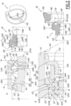
- FIG. 4 shows a way of producing the seals 48, 68 and 88 by overmolding, respectively on the body 42 and on the valve 66, more particularly on its front part 66A.
- Insert C represents the manufacture of the seal 48
- insert D represents the manufacture of seals 68 and 88.
- the upper part shows a situation before injection of the material intended to constitute the joints
- the lower part shows the molded joints. Channels, used to guide the injected material towards molding cavities of the seals, are not shown.
- the seal 48 is overmolded on the male tubular body 42 within a cavity C48 defined between parts 42, 102 and 104, while the seals 68 and 88 are overmolded on the front part 66A of the valve 66 in cavities C68 and C88 defined respectively between parts 66A, 202 and 204, for cavity C68, and between parts 66A, 202 and 203, for cavity C88.
- connection plate 10 When the male and female elements 4 and 6 are coupled, they are gradually brought together, by moving the connection plate 10 towards the connection plate 8, in the direction of the arrow F10, to pass successively of the uncoupled configuration shown in figure 1 in the three configurations shown in Figure 3 .
- a guide cone provided at the front distal end 624 of the female tubular body 62 makes it possible to align the axis X4 with the fitting axis X2, subject to possible movement of the male tubular body 42 in the bore 14.
- the guide surfaces formed by the surfaces S624A and S624B contribute to the correct alignment of the axes X4 and X6 on the axis X2, during coupling.
- the respective front surfaces S48 and S68 of the seals 48 and 68 bear against each other parallel to the fitting axis X2, this being obtained by means of a retraction of the valve 46 to the inside the male tubular body 42, under the action of the head 644 of the pusher 64 which pushes the valve 46 from its advanced position towards its retracted position against the force exerted by the elastic member 49.
- the first S48 and second S68 front surfaces of the first 48 and second 68 seals are capable of coming into contact with each other at the fitting of the male and female elements of the quick connector 2.
- the valve has left its seat formed by the split ring 50 and moves back into the cavity formed by the volume V42.
- the frontal sealing of the first and second frontal surfaces S48 and S68 in some way takes over from the loss of sealing of the radial surfaces 486 and 686 of the seals 48 and 68 on the valve 46 and the pusher 64 respectively.
- the fluid passage between volumes V42 and V62 is optimized.
- this fluid circulates in the annular volume delimited by the seals 48 and 68 around the rod of the pusher 64, through the distal mouths 428 and 628 which are surrounded radially by the internal radial surfaces S486 and S686 of the seals sealing 48 and 68 whose front surfaces S48 and S68 are in axial support, parallel to the fitting axis X2.
- this phase of return of the elements 644 and 42 into the interior volume defined by the seals 48 and 68 has the effect of cleaning the walls external cylindrical parts of the valve 46 and the head 644 of the pusher 64, before the front surfaces S48 and S68 of the seals are separated from each other and the valve 46 comes to rest again on its seat formed by the molten ring 50.
- the cylindrical and external walls S46B of the valve and S644 of the pusher are free of any drop of fluid which has passed between the longitudinal cavities V42 and V62, in the coupled configuration of the quick connector 2.
- the outer seal 88 mounted on the drawer 66 ensures the sealing of the movable drawer 66 with the female tubular body 62, while remaining in contact with the surface S62.
- the male element 4 of the quick connector 2 is fixedly mounted in the connection plate 8, by means of a thread and a tapping provided respectively on the exterior of the male tubular body 42 and in the bore 14, in which opens the pipe 12.
- a seal 43 is interposed between parts 4 and 8 and a collar 426 provided outside the male tubular body 42 bears against a front face 81 of the connection plate 8.
- the front part of the male element in particular the distal end 424 of the male tubular body 42, is similar to that of the first embodiment and comprises a valve 46, a seal 48 whose front surface S48 is arranged in front of an edge plane P4 defined as in the first embodiment, along a longitudinal axis X4 of the male element 4.
- no split ring is provided and the frustoconical surface S46A of the valve 46 bears against a corresponding frustoconical surface 425 formed on the inside of the distal end 424, when the valve 46 closes the distal mouth 428.
- the seal 48 differs from that of the first embodiment in that its rear surface S'48 has a more marked concavity.
- connection plate 10 is bipartite and comprises a front plate part 10A and a rear part of plate 10B which are assembled, by means not shown, so as to accommodate both a rear part of the female tubular body 62 and a front part thereof which has a diameter greater than that of the rear part due to the existence of a collar 626 in which two orifices 627 are provided forming passages for cleaning air from any drippings formed at the interface between the male and female elements 4 and 6.
- the orifices 627 are aligned with orifices 107 provided in the front part of plate 10A, these orifices being themselves selectively supplied with air under pressure according to needs, as explained below, thanks to an air source and valves not shown.
- the flange 626 of the female element 6 is equipped with two seals 63 mounted on its front and rear faces and respectively bearing against two flat faces of the parts 10A and 10B of the connection plate.
- the seals 63 provide a seal between the passages 107 and 627, on the one hand, and the part of the bore 18 located between these orifices, on the other hand, with respect to the rest of the bore 18.
- An O-ring 65 is housed in an internal peripheral groove 623 of the female tubular body 62 and intended to come into contact with the external peripheral surface of the male tubular body 42, in front of the collar 426.
- the second seal 68 and the third seal 88 are in one piece together.
- the joints 68 and 88 are made in a single piece by being connected by four oblique holes made in the valve 66, two of which are located in the plane of the figures 5 And 6 and in the plane of the upper part of the figure 7 but not in the plane of the lower part of this figure 7 . These holes correspond to the grayed volume bearing the reference 78 in the Figure 6 .
- Another difference compared to the first embodiment concerns the fact that the drawer is here in one piece, such that the elastic return member 69 comes to bear directly against the part of the valve on which the seals 68 and 88 are overmolded.
- the manufacture of the seals 68 and 88 comprises a machining step complementary to those of the first embodiment and consisting of producing, after the overmolding of the seal 68, a groove 688 on the rear of this seal.
- sealing 68 which gives the rear surface concavity S'68 a more pronounced character than in the first embodiment, as clearly visible at the Figure 6 .
- the rear surface S'48 of the seal 48 is provided with a machined groove 488, which gives it a more pronounced concavity.
- the grooves 488 and 688 are made by turning, using an angled tool. This method of obtaining the concavity of the surfaces S'48 and S'68 is interesting when the overmolding processes do not allow the use of a counter-form to produce the concave rear surfaces S'48 and S'68, particularly when the diameters of the grooves 488 and 688 are greater than the internal diameters of the seals, as considered below.
- grooves 488 and 688 give good flexibility to the joints 48 and 68 which can thus easily adapt to the geometry of the mouth 428 or 628 into which they penetrate.
- the pressure in the grooves 488 and 688 has the effect of holding the surfaces S48 and S68 against each other and confirming the sealing barrier with the outside in the coupled configuration.
- ⁇ 488 the maximum diameter of the groove 488 and ⁇ 688 the maximum diameter of the groove 688.
- the diameters ⁇ 488 and ⁇ 688 are respectively equal to the diameters maximum of surfaces S'48 and S'68.
- the diameter ⁇ 488 is greater than the diameter ⁇ 486, while the diameter ⁇ 688 is greater than the diameter ⁇ 686.
- the diameter ⁇ 42 is greater than the diameter ⁇ 486, therefore the maximum diameter of the surface S'48.
- four radial holes 666 are provided in the drawer 666 and allow pressure balancing between the internal volume V62 of the female tubular body 62 and a groove 669 formed in the rear and external part of the seal 88.
- This groove 669 can be manufactured in the same way as the groove 668 or in another way.
- the respective front faces S48 and S68 of the seals 48 and 68 are each more advanced than an edge plane P4 or P6 defined as in the first embodiment.
- Axial offsets ⁇ 4 and ⁇ 6 defined as in the first embodiment each have a non-zero value.
- the external diameter ⁇ 644 of the head 644 is 9.4 mm and the maximum internal diameter ⁇ 686 of the seal 68 defined by its surface S686 has a variable value between a maximum value of 9.1 mm and a minimum value of 8.9 mm, the minimum value being present at the level of the bead 686.
- the internal wall S686 of the seal 68 has a length L686 parallel to the axis X6 equal to 2 mm, while the S68 front wall is 1 mm thick.
- the operation of the second embodiment is comparable to that of the first embodiment, except with regard to the fact that air can be injected into the ports 107 and 627, before the front surfaces S48 and S68 of the seals seals 48 and 68 do not come into contact. This makes it possible to clean the front faces 462 and 642 and the front surfaces S48 and S68 of any pollution potentially present before coupling the quick connector.
- the effect of the fluid pressure on the rear surfaces S'48 and S'68 of the seals 48 and 68 is increased compared to the first mode in uncoupled configuration.
- the pressure in the grooves 488 and 688 has the effect of holding the surfaces S48 and S68 against each other and of confirming the sealing barrier with the outside, in coupled configuration.
- the elements 4 and 6 of the quick connector 2 are not mounted on connection plates but each comprise a rear body 42', respectively 62', screwed onto the male or female tubular body 42 or 62 and adapted to fit directly with a flexible or rigid pipe forming a pipe 12 or 16, by means of clamps not shown.
- the two seals 48 and 68 are here identical to those of the second embodiment, as well as the internal structure of the male and female elements 4 and 6, in particular with regard to the valve 46, the drawer 44 and the pusher 64 .
- the respective front faces S48 and S68 of the seals 48 and 68 are each more advanced than an edge plane P4 or P6 defined as in the first embodiment.
- Axial offsets ⁇ 4 and ⁇ 6 defined as in the first embodiment each have a non-zero value.
- locking means are provided for locking the male and female elements in the coupled configuration of the quick connector.
- These locking means comprise locking balls 202 housed in radial spaces 204 of the female tubular body 62, while the male tubular body 42 is provided with an external peripheral groove 206 for partially receiving these locking balls, in coupled configuration of the quick connector 2.
- the locking balls 202 are controlled by means of an external ring 208 movably mounted around the female tubular body 62, along the longitudinal axis X6.
- the locking ring 208 When coupling or uncoupling the male and female elements 4 and 6, the locking ring 208 must be maneuvered, against an elastic force exerted by a spring 210, in order to allow a centripetal radial movement and limited amplitude of the balls 202 in the radial spaces 204.
- the external radial surface of the male tubular body 42 in the vicinity of its distal end 424 has a diameter ⁇ 42 equal to the internal diameter ⁇ 623 of an internal flange 623 of the female tubular body 62.
- the axial movements of the male and female elements 4 and 6 are exerted by acting directly on their respective bodies or on the rear parts 42' and 62'.
- the operation is identical to that of the first embodiment.
- the invention offers a quick connection solution which limits, or even completely eliminates, the risks of dripping due to the fact that there is no of space between the external radial walls S46B of the valve and S644 of the pusher head when their front faces 462 and 642 are in contact, which avoids creating a fluid retention zone.
- the invention is also remarkable in that it uses a limited number of valve seals, apart from the seals 48, 68 and 88. This is appreciable in terms of cost price and complexity of manufacturing and maintenance.
- the sealing produced between the seals 48 and 68 at the connection and disconnection of the quick connector 2, that is to say at the coupling and uncoupling of elements 4 and 6, avoids the risk of dripping throughout these operations, as well as the inclusion of air in the fluid vein during connection.
- seals 48 and 68 have identical or similar geometries, they can be produced, in certain cases at least, from the same overmolding and/or machining tools.
- the seal 48 and/or 68 is devoid of beads 486 and 686.
- their internal surface 486 and/or 686 is cylindrical with a rectilinear generatrix.
- the seals 48 and 68 can be obtained by molding, by overmolding, by machining or by any other process accessible to those skilled in the art and have shapes of seal walls adapted to those of the parts with which they interact.
- the value of the distances d4 and d6 can be adapted according to the other dimensions of the male and female elements of the connection. For example, for an application requiring a connecting element with a diameter ⁇ 42 of 20m and a connecting element with a diameter ⁇ 624 of 20mm, the values of d4 and d6 will be adapted between 1 and 3mm, preferably to 1.5mm.
- Maintaining the coupling elements in the coupled configuration, as well as moving them between the uncoupled and coupled configurations, can be carried out by means other than the connection plates 8 and 10 and the ball locking system 202 mentioned above.
- the seals 48 and 68 can be made of any material compatible with their function and with contact with the fluid passing through the quick connector 2, in particular in elastomer, as envisaged above, in silicone or in polytetrafluoroethylene.
Landscapes
- Engineering & Computer Science (AREA)
- General Engineering & Computer Science (AREA)
- Mechanical Engineering (AREA)
- Quick-Acting Or Multi-Walled Pipe Joints (AREA)
Claims (17)
- Schnellkupplung (2) zur lösbaren Verbindung zweier Leitungen (12, 16), die von einem unter Druck stehenden Fluid durchströmt werden,- diese Schnellkupplung umfassend ein Steckelement (4) und ein Buchsenelement (6), die geeignet sind, um entlang einer Einsteckachse (X2) zwischen einer entkuppelten Konfiguration und einer gekuppelten Konfiguration der Schnellkupplung zusammengesteckt zu werden,- das Steckelement (4) umfassend∘ einen rohrförmigen Steckkörper (42), der sich entlang einer ersten Längsachse (X4) zwischen einem proximalen Ende (422) und einem distalen Ende (424) erstreckt und der Folgendes aufweist▪ einen ersten Längshohlraum (V42) für den Durchgang von unter Druck stehendem Fluid in der gekoppelten Konfiguration der Schnellkupplung,▪ eine erste Randebene (P4), die an der Außenseite des distalen Endes (424) des rohrförmigen Steckkörpers ausgebildet ist und senkrecht zu der ersten Längsachse ist;∘ eine erste distale Mündung (428), die durch das distale Ende (424) des rohrförmigen Steckkörpers definiert ist und deren Durchmesser (ϕ428) kleiner ist als ein Durchmesser (ϕ42) des ersten Längshohlraums;o eine Klappe (46), die entlang der ersten Längsachse (X4) zwischen einer vorgeschobenen Position, in der es das erste distale Mundstück (428) verschließt, und einer zurückgezogenen Position, in der es das erste distale Mundstück nicht verschließt, beweglich ist;o eine erste Dichtung (48);- das Buchsenelement (6) umfassend∘ einen rohrförmigen Buchsenkörper (62), der sich entlang einer zweiten Längsachse (X6) zwischen einem proximalen Ende (622) und einem distalen Ende (624) erstreckt und Folgendes umfasst▪ einen zweiten Längshohlraum (V62) für den Durchgang von unter Druck stehendem Fluid in der gekoppelten Konfiguration der Schnellkupplung,∘ ein zweites distales Mundstück (628), dessen Durchmesser (cp628) kleiner ist als ein Durchmesser (cp62) des zweiten Längshohlraums;o einen Stößel (64), der geeignet ist, um die bewegliche Klappe (46) aus ihrer vorgeschobenen Position in ihre zurückgezogene Position entlang der ersten Längsachse (X4) zu drücken;o einen Schieber (66),▪ der um den Stößel montiert ist,▪ der entlang der zweiten Längsachse (X6) zwischen einer vorgeschobenen Position, in der er das zweite distale Mundstück (628) verschließt, und einer zurückgezogenen Position, in der er das zweite distale Mundstück nicht verschließt, beweglich ist, und▪ der eine zweite Randebene (P6) aufweist, die an der Außenseite eines distalen Endes (667) des Schiebers ausgebildet ist und senkrecht zu der zweiten Längsachse (X6) ist;o eine zweite Dichtung (68), die teilweise in einer Kehle (663) des Schiebers untergebracht ist und an einer Wand (S644) des Schiebers (64) anliegt, wenn der Schieber (66) in der vorgeschobenen Position ist,- wobei die erste Dichtung auf einer zylindrischen Oberfläche (S46B) der beweglichen Klappe (46) in einer Richtung radial zu der ersten Längsachse (X4) anliegt, wenn diese bewegliche Klappe in der vorgeschobenen Position ist;- die zweite Dichtung umfassend eine zweite Stirnfläche (S68), die entlang der zweiten Längsachse (X6) weiter vorsteht ist als die zweite Randebene (P6);dadurch gekennzeichnet, dass- die erste Dichtung (48) teilweise in einer Kehle (423) des rohrförmigen Steckkörpers (42) untergebracht ist;- wenn der Schieber (66) in der vorgeschobenen Position ist, die zweite Dichtung (68) an einer zylindrischen Wand (S644) des Schiebers (64) in einer Richtung radial zu der zweiten Längsachse (X6) anliegt;- die erste Dichtung eine erste Stirnfläche (S48) umfasst, die entlang der ersten Längsachse (X4) weiter vorsteht als die erste Randebene (P4); und- die erste (S48) und die zweite (S68) Stirnfläche der ersten (48) und der zweiten (68) Dichtung geeignet sind, um beim Zusammenstecken des Steck- (4) und des Buchsenelements (6) der Schnellkupplung (2) miteinander in Kontakt zu kommen.
- Schnellkupplung nach Anspruch 1, dadurch gekennzeichnet, dass- wenn die Klappe (46) in der vorgeschobenen Position ist, die erste Dichtung (48) ein ringförmiges Volumen (V428) einnimmt, das radial zu der ersten Längsachse (X4) zwischen dem rohrförmigen Steckkörper (42) und der Klappe und axial entlang der ersten Längsachse vor der Kehle (423) des rohrförmigen Steckkörpers (42) und hinter der ersten Randebene (P4) definiert ist und/oder- wenn der Schieber (66) in der vorgeschobenen Position ist, die zweite Dichtung (68) ein ringförmiges Volumen (V628) einnimmt, das radial zu der zweiten Längsachse (X6) zwischen dem Schieber (64) und dem distalen Ende (667) des Schiebers und axial entlang der zweiten Längsachse vor der Kehle (663) des Schiebers und hinter der zweiten Randebene (P6) definiert ist.
- Schnellkupplung nach einem der vorherigen Ansprüche, dadurch gekennzeichnet, dass- die Klappe (46) eine Vorderseite (462) aufweist, die von dem ersten Hohlraum (V42) wegweist und axial entlang der ersten Längsachse (X4) vor der ersten Stirnfläche (S48) in der vorgeschobenen Position der Klappe angeordnet ist, und/oder- der Schieber (64) eine Vorderseite (642) aufweist, die von dem zweiten Hohlraum (V62) wegweist und axial entlang der zweiten Längsachse (X6) vor der zweiten Stirnfläche (S68) in der vorgeschobenen Position der Schieber (66) angeordnet ist.
- Schnellkupplung nach einem der vorherigen Ansprüche, dadurch gekennzeichnet, dass- die erste Dichtung (48) Folgendes umfasst∘ einen ersten Blockierabsatz (482) in der Kehle (423) des rohrförmigen Steckkörpers (42), wobei dieser erste Absatz durch eine erste Kontaktfläche (S482) mit der Kehle des rohrförmigen Steckkörpers begrenzt ist,∘ eine erste Innenfläche (S486), die bereitgestellt ist, um an der zylindrischen Wand (S46B) der Klappe anzuliegen, und∘ einen Wulst (486), dessen unbelasteter Durchmesser (ϕ486) kleiner ist als ein Außendurchmesser (ϕ46B) der Klappe (46) und der von der ersten Innenfläche begrenzt ist; und/oder- wobei die zweite Dichtung (68) Folgendes umfassto einen zweiten Blockierabsatz (682) in der Kehle (663) des Schieber (66), wobei dieser zweite Absatz durch eine zweite Kontaktfläche (S682) mit dieser Kehle des Schiebers begrenzt ist,∘ eine zweite Innenfläche (S686), die bereitgestellt ist, um an der zylindrischen Wand (S644) des Stößels anzuliegen, und∘ einen Wulst (686), dessen unbelasteter Durchmesser (ϕ686) kleiner ist als ein Außendurchmesser (Φ644) des Stößels (64) und der durch die zweite Innenfläche begrenzt ist.
- Schnellkupplung nach dem vorherigen Anspruch, dadurch gekennzeichnet, dass- die erste Dichtung (48) eine erste hintere Fläche (S'48) umfasst, die∘ dem ersten Längshohlraum (V42) zugewandt ist,∘ mit der ersten Kontaktfläche (S482) mit der ersten Innenfläche (S486) verbunden ist, und∘ konkav geformt ist, und/oder- die zweite Dichtung (68) eine zweite hintere Fläche (S'68) umfasst, die∘ dem zweiten Längshohlraum (V62) zugewandt ist,∘ mit der zweiten Kontaktfläche (S682) mit der zweiten Innenfläche (S686) verbunden ist, und∘ konkav geformt ist.
- Schnellkupplung nach dem vorherigen Anspruch, dadurch gekennzeichnet, dass- die erste hintere Fläche (S'48), die eine erste Nut (488) begrenzt, die in der vorgeschobenen Position der Klappe zu dem ersten Längshohlraum (V42) hin offen ist und deren maximaler Durchmesser (ϕ488) größer ist als ein minimaler Durchmesser (ϕ482) der ersten Kontaktfläche (482), und/oder- die zweite hintere Fläche (S'68), die eine zweite Nut (688) begrenzt, die in der vorgeschobenen Position der Klappe zu dem zweiten Längshohlraum (V62) hin offen ist und deren maximaler Durchmesser (ϕ688) größer ist als ein minimaler Durchmesser (ϕ682) der zweiten Kontaktfläche (S682), und/oder.
- Schnellkupplung nach einem der Ansprüche 5 oder 6, dadurch gekennzeichnet, dass hinter der Kehle (423) der rohrförmige Steckkörper (42) einen Innendurchmesser (ϕ42) aufweist, der größer ist als ein maximaler Durchmesser (ΦS'48) der ersten hinteren Fläche (S'48).
- Schnellkupplung nach dem vorherigen Anspruch, dadurch gekennzeichnet, dass das Steckelement (4) einen Ring (50) umfasst,- der in den rohrförmigen Steckkörper (42) eingesetzt ist;- konfiguriert ist, um einen Sitz (S50) zur Anlage der Klappe (46) in der vorgeschobenen Position zu bilden, und- dessen Innendurchmesser (ϕS50) kleiner ist als ein maximaler Durchmesser (ΦS'48) der ersten hinteren Fläche (S'48).
- Schnellkupplung nach einem der vorherigen Ansprüche, dadurch gekennzeichnet, dass das Steckelement (4) ein erstes elastisches Rückstellglied (49) umfasst, das konfiguriert ist, um die Klappe (46) in die vorgeschobene Position zurückzustellen, und das Buchsenelement ein zweites elastisches Rückstellglied (69) umfasst, das konfiguriert ist, um den Schieber (66) in die vorgeschobene Position zurückzustellen.
- Schnellkupplung nach dem vorherigen Anspruch, dadurch gekennzeichnet, dass der Schieber (66) aus einem vorderen Abschnitt (66A), der die Kehle (663) umfasst, in der die zweite Dichtung (68) teilweise aufgenommen ist, und einem hinteren Abschnitt (66B) gebildet ist, der an den vorderen Abschnitt angesetzt ist, der eine proximale Auflagefläche (S'66) für das zweite elastische Rückstellglied umfasst und dessen Innendurchmesser (ϕ66) kleiner ist als ein minimaler Durchmesser (ϕ682) der zweiten Kontaktfläche (S682).
- Schnellkupplung nach einem der vorherigen Ansprüche, dadurch gekennzeichnet, dass der Schieber (66) eine dritte Dichtung (88) trägt, die in der vorgeschobenen und in der zurückgezogenen Position des Schiebers mit dem rohrförmigen Buchsenkörper (62) in Kontakt ist.
- Schnellkupplung nach einem der vorherigen Ansprüche, dadurch gekennzeichnet, dass in der gekuppelten Konfiguration der Schnellkupplung (2) die erste Stirnfläche (S48) parallel zu der Einsteckachse (X2) axial an der zweiten Stirnfläche (S68) anliegt.
- Schnellkupplung nach Anspruch 3, dadurch gekennzeichnet, dass- wenn die Klappe (46) in der vorgeschobenen Position ist, sich die erste Stirnfläche (S48) entlang der ersten Längsachse (X4) zwischen der ersten Randebene (P4) und einer ersten Ebene (π4) parallel zu der ersten Randebene, senkrecht zu der ersten Längsachse (X4) und durch die Vorderseite (462) der Klappe befindet, und- wenn die Klappe in der vorgeschobenen Position ist, die erste Randebene (P4) und die erste parallele Ebene (π4) durch einen Abstand (d4) von weniger als oder gleich wie 1 mm entlang dieser Achse getrennt sind, und/oder- wenn der Schieber (66) in der vorgeschobenen Position ist, sich die zweite Stirnfläche (S68) entlang der zweiten Längsachse X6 zwischen der zweiten Randebene (P4) und einer zweiten Ebene parallel (π6) zu der ersten Randebene, senkrecht zur zweiten Längsachse (X6) und durch die Vorderseite (642) des Stößels (64) befindet, und- wenn der Schieber in der vorgeschobenen Position ist, die zweite Randebene (P6) und die zweite parallele Ebene (π6) durch einen Abstand (d6) von weniger als oder gleich wie 1 mm entlang dieser Achse getrennt sind.
- Schnellkupplung nach einem der Ansprüche 3 und 13, dadurch gekennzeichnet, dass in der gekoppelten Konfiguration der Schnellkupplung (2),- der Stößel (64) die Klappe (46) in der zurückgezogenen Position hält;- das unter Druck stehende Fluid frei zwischen dem ersten und dem zweiten Längshohlraum (V42, V62) fließen kann (E); und- das distale Ende (424) des rohrförmigen Steckkörpers (42) und eine Vorderseite (662) des Schiebers (66) entlang der Einsteckachse (X2) um einen Abstand (d46) ungleich Null voneinander beabstandet sind.
- Schnellkupplung nach einem der vorherigen Ansprüche, dadurch gekennzeichnet, dass die erste Dichtung (48) und die zweite Dichtung (68) identisch sind.
- Schnellkupplung nach einem der vorherigen Ansprüche, dadurch gekennzeichnet, dass- das Buchsenelement (6) mindestens zwei Lagerflächen (S624A, S624B) umfasst, die auf der zweiten Längsachse (X6) zentriert sind;- die Lagerflächen konfiguriert sind, um das Steckelement (4) beim Einstecken zu führen; und- die Lagerflächen einen gemeinsamen Führungsdurchmesser (ϕ624) aufweisen und entlang der zweiten Längsachse um einen Abstand (d624) versetzt sind, der größer als oder gleich wie ein Fünftel des gemeinsamen Führungsdurchmessers ist.
- Anordnung (1) zum Verbinden einer beweglichen Kupplungsplatte (10) mit mindestens einer festen Kupplungsplatte (8), insbesondere zum Verbinden von Kreisläufen vom Typ Hydraulik, dadurch gekennzeichnet, dass- die Verbindungsanordnung mindestens eine Schnellkupplung (2) nach einem der vorherigen Ansprüche umfasst;- das Steckelement (4) der Schnellkupplung und das Buchsenelement (6) der Schnellkupplung jeweils an einer von der beweglichen und der festen Platte montiert sind, die von einer Leitung (12, 16) durchquert wird, die fluidisch mit dem ersten oder dem zweiten Längshohlraum (V42, V62) des Kupplungselements verbunden ist; und- eine erste Platte (8; 10) von der beweglichen Platte und der festen Platte mit einem Halteflansch (84; 10A) des auf dieser ersten Platte montierten Steck- oder Buchsenelements ausgestattet ist, wobei dieser Halteflansch eine Bewegung Steck- oder Buchsenelements in Bezug auf die erste Platte in einer Ebene senkrecht zu der ersten oder der zweiten Längsachse (X4; X6) des auf dieser ersten Platte montierten Steck- oder Buchsenelements ermöglicht.
Applications Claiming Priority (1)
| Application Number | Priority Date | Filing Date | Title |
|---|---|---|---|
| FR2110833A FR3128001B1 (fr) | 2021-10-13 | 2021-10-13 | Raccord rapide et ensemble de connexion comprenant un tel raccord rapide |
Publications (2)
| Publication Number | Publication Date |
|---|---|
| EP4166836A1 EP4166836A1 (de) | 2023-04-19 |
| EP4166836B1 true EP4166836B1 (de) | 2024-07-17 |
Family
ID=79831361
Family Applications (1)
| Application Number | Title | Priority Date | Filing Date |
|---|---|---|---|
| EP22201166.0A Active EP4166836B1 (de) | 2021-10-13 | 2022-10-12 | Schnellkupplung und verbindungsanordnung mit einer solchen schnellkupplung |
Country Status (7)
| Country | Link |
|---|---|
| US (1) | US11873934B2 (de) |
| EP (1) | EP4166836B1 (de) |
| KR (1) | KR20230052830A (de) |
| CN (1) | CN115962357A (de) |
| CA (1) | CA3178597A1 (de) |
| FR (1) | FR3128001B1 (de) |
| PT (1) | PT4166836T (de) |
Families Citing this family (2)
| Publication number | Priority date | Publication date | Assignee | Title |
|---|---|---|---|---|
| CN110500463B (zh) * | 2019-07-17 | 2021-08-20 | 华为技术有限公司 | 一种接头、冷却系统和计算机装置 |
| TWI860241B (zh) * | 2024-02-01 | 2024-10-21 | 富世達股份有限公司 | 快速接頭總成 |
Family Cites Families (28)
| Publication number | Priority date | Publication date | Assignee | Title |
|---|---|---|---|---|
| US2319015A (en) * | 1941-02-11 | 1943-05-11 | Cleveland Pneumatic Tool Co | Valve coupling |
| US4991627A (en) * | 1986-08-25 | 1991-02-12 | Automotive Products Plc | Connector for modular prefilled hydraulic control apparatus |
| US4886301A (en) * | 1988-05-05 | 1989-12-12 | Preece Incorporated | Quick disconnect with a position compensating seal |
| US5215122A (en) * | 1991-12-09 | 1993-06-01 | Aeroquip Corporation | Quick disconnect fluid coupling with integral pressure relief feature |
| JP2559233Y2 (ja) * | 1993-07-07 | 1998-01-14 | 日東工器株式会社 | 管継手 |
| US5398723A (en) * | 1994-02-28 | 1995-03-21 | Aeroquip Corporation | Fluid coupling with adjustable pressure relief valve |
| US5709243A (en) * | 1995-11-20 | 1998-01-20 | Aeroquip Corporation | Low spill female coupling |
| US5911403A (en) * | 1996-04-12 | 1999-06-15 | Colder Products Company | Valve and method for assembling the same |
| US7547047B2 (en) * | 2003-07-02 | 2009-06-16 | Colder Products Company | Coupler and method of making molded coupler |
| JP4499553B2 (ja) * | 2004-12-28 | 2010-07-07 | 日東工器株式会社 | 管継手の継手部材 |
| ITMI20060863A1 (it) * | 2006-05-03 | 2007-11-04 | Faster Spa | Innesto rapido |
| FR2919706B1 (fr) * | 2007-07-30 | 2009-10-09 | Staubli Faverges Sca | Element de raccord rapide et raccord rapide comprenant un tel element |
| FR2933162B1 (fr) * | 2008-06-30 | 2010-08-20 | Staubli Sa Ets | Element de raccord a griffes et raccord incorporant un tel element |
| US20130312846A1 (en) * | 2012-05-25 | 2013-11-28 | André Sloth Eriksen | Fluid connector for a cooling system |
| ITMI20130525A1 (it) * | 2013-04-05 | 2014-10-06 | Alfa Gomma S P A | Dispositivo di innesto rapido per fluido in pressione |
| FR3007817B1 (fr) | 2013-06-28 | 2015-07-17 | Staubli Sa Ets | Element femelle de raccord rapide et raccord rapide comprenant un tel element |
| CA2896454C (en) * | 2014-07-08 | 2021-12-07 | Staubli Faverges | Connecting plug, cooling circuit equipped with such a connecting plug and method for connecting such a cooling circuit and a cold plate |
| DE102014010570B4 (de) * | 2014-07-16 | 2023-10-12 | U.M. Gewerbeimmobilien Gmbh & Co. Kg | Kupplungsteil für eine Kupplung für Druckmittelleitungen |
| KR102155496B1 (ko) * | 2016-05-24 | 2020-09-14 | 니토 코키 가부시키가이샤 | 암형 커플링 부재와 수형 커플링 부재로 이루어지는 관 커플링 |
| FR3052226B1 (fr) * | 2016-06-07 | 2019-05-10 | Staubli Faverges | Element de raccord rapide avec organe de decharge et raccord rapide comprenant un tel element |
| US10781957B2 (en) * | 2017-01-24 | 2020-09-22 | Staubli Faverges | Fluid coupling element and fluid-coupling comprising such an element |
| SE544207C2 (en) * | 2017-09-08 | 2022-03-01 | Steelwrist Ab | Hydraulic coupling device and method of mounting the same |
| SE542889C2 (en) * | 2017-09-08 | 2020-08-11 | Steelwrist Ab | Hydraulic coupling device and female coupling unit |
| FR3084437B1 (fr) | 2018-07-24 | 2020-10-16 | Staubli Sa Ets | Raccord rapide pour la jonction amovible de deux canalisations parcourues par un fluide sous pression |
| FR3101389B1 (fr) * | 2019-09-30 | 2021-10-22 | Staubli Sa Ets | Raccord fluidique |
| US11486528B2 (en) * | 2019-11-15 | 2022-11-01 | Parker-Hannifin Corporation | Quick-coupling with automatic locking mechanism |
| US11619334B2 (en) * | 2019-12-31 | 2023-04-04 | Colder Products Company | Fluid couplings |
| WO2021252197A1 (en) * | 2020-06-12 | 2021-12-16 | Colder Products Company | Fluid couplings |
-
2021
- 2021-10-13 FR FR2110833A patent/FR3128001B1/fr active Active
-
2022
- 2022-10-07 CA CA3178597A patent/CA3178597A1/fr active Pending
- 2022-10-12 KR KR1020220130404A patent/KR20230052830A/ko active Pending
- 2022-10-12 PT PT222011660T patent/PT4166836T/pt unknown
- 2022-10-12 EP EP22201166.0A patent/EP4166836B1/de active Active
- 2022-10-13 US US17/965,741 patent/US11873934B2/en active Active
- 2022-10-13 CN CN202211255713.3A patent/CN115962357A/zh active Pending
Also Published As
| Publication number | Publication date |
|---|---|
| US11873934B2 (en) | 2024-01-16 |
| EP4166836A1 (de) | 2023-04-19 |
| FR3128001B1 (fr) | 2023-10-27 |
| US20230250909A1 (en) | 2023-08-10 |
| FR3128001A1 (fr) | 2023-04-14 |
| KR20230052830A (ko) | 2023-04-20 |
| CN115962357A (zh) | 2023-04-14 |
| CA3178597A1 (fr) | 2023-04-13 |
| PT4166836T (pt) | 2024-08-27 |
Similar Documents
| Publication | Publication Date | Title |
|---|---|---|
| EP2439440B1 (de) | Anschlussvorrichtung mit Verriegelung durch Gewindegriffe, und Anschluss, der eine solche Vorrichtung enthält | |
| FR2473152A1 (fr) | Dispositif de couplage deconnectable pour un tuyau | |
| EP2088358B1 (de) | Verbindungssteckerelement und Schnellverbindung, die ein solches Element beinhaltet | |
| EP3670992B1 (de) | Anschlussbuchse und fluidanschluss, der ein steckanschlusselement sowie diese anschlussbuchse umfasst | |
| EP2278205B1 (de) | Kupplungsaufnahme und diese beinhaltende Schnellkupplung | |
| EP3220034B1 (de) | Kupplungselement für die verbindung von flüssigkeitsführenden bauteilen und kupplung mit einem solchen element. | |
| EP3196526B1 (de) | Schnellkupplung für die lösbare verbindung von leitungen für fluide unter druck | |
| FR2786848A1 (fr) | Coupleur a billes | |
| FR2933162A1 (fr) | Element de raccord a griffes et raccord incorporant un tel element | |
| EP3184870B1 (de) | Buchse eines schnellanschlusses, und eine solche buchse umfassender schnellanschluss | |
| FR3007818A1 (fr) | Connecteur fluidique avec serrage de tube integre. | |
| EP4166836A1 (de) | Schnellkupplung und verbindungsanordnung mit einer solchen schnellkupplung | |
| EP3599408B1 (de) | Schnellkupplung für die lösbare verbindung von zwei rohren, durch die eine flüssigkeit unter druck fliesst | |
| EP3742037B1 (de) | Anschlussbuchse eines fluidanschlusses, untereinheit zum anschliessen und anschluss, der eine solche anschlussbuchse umfasst | |
| EP4306837B1 (de) | Anschlusselement für eine fluidverbindung an ein endgerät | |
| FR3120675A1 (fr) | Élément femelle de raccord rapide, et raccord rapide comprenant un tel élément femelle et un élément mâle associé | |
| EP4124788A1 (de) | Steckanschlusselement eines fluidanschlusses und ein solches steckelement umfassender fluidanschluss | |
| CA3050196A1 (fr) | Raccord rapide pour la jonction amovible de deux canalisations parcourues par un fluide sous pression | |
| EP3798490A1 (de) | Fluidanschlusselement | |
| EP4227566B1 (de) | Fluidanschlussbuchse und fluidkupplung mit einer solchen buchse | |
| EP4497986B1 (de) | Verbindungselement und verfahren zur herstellung eines solchen verbindungselements | |
| FR3165054A1 (fr) | Elément et ensemble de raccord fluidique | |
| EP4497987A1 (de) | Verbindungselement und verfahren zur herstellung eines solchen verbindungselements | |
| FR2790057A1 (fr) | Coupleur a billes | |
| FR2865790A1 (fr) | Element male ou femelle de raccord rapide et raccord rapide comprenant un tel element |
Legal Events
| Date | Code | Title | Description |
|---|---|---|---|
| PUAI | Public reference made under article 153(3) epc to a published international application that has entered the european phase |
Free format text: ORIGINAL CODE: 0009012 |
|
| STAA | Information on the status of an ep patent application or granted ep patent |
Free format text: STATUS: THE APPLICATION HAS BEEN PUBLISHED |
|
| AK | Designated contracting states |
Kind code of ref document: A1 Designated state(s): AL AT BE BG CH CY CZ DE DK EE ES FI FR GB GR HR HU IE IS IT LI LT LU LV MC ME MK MT NL NO PL PT RO RS SE SI SK SM TR |
|
| STAA | Information on the status of an ep patent application or granted ep patent |
Free format text: STATUS: REQUEST FOR EXAMINATION WAS MADE |
|
| 17P | Request for examination filed |
Effective date: 20230921 |
|
| RBV | Designated contracting states (corrected) |
Designated state(s): AL AT BE BG CH CY CZ DE DK EE ES FI FR GB GR HR HU IE IS IT LI LT LU LV MC ME MK MT NL NO PL PT RO RS SE SI SK SM TR |
|
| GRAP | Despatch of communication of intention to grant a patent |
Free format text: ORIGINAL CODE: EPIDOSNIGR1 |
|
| STAA | Information on the status of an ep patent application or granted ep patent |
Free format text: STATUS: GRANT OF PATENT IS INTENDED |
|
| INTG | Intention to grant announced |
Effective date: 20240207 |
|
| P01 | Opt-out of the competence of the unified patent court (upc) registered |
Effective date: 20240420 |
|
| GRAS | Grant fee paid |
Free format text: ORIGINAL CODE: EPIDOSNIGR3 |
|
| GRAA | (expected) grant |
Free format text: ORIGINAL CODE: 0009210 |
|
| STAA | Information on the status of an ep patent application or granted ep patent |
Free format text: STATUS: THE PATENT HAS BEEN GRANTED |
|
| AK | Designated contracting states |
Kind code of ref document: B1 Designated state(s): AL AT BE BG CH CY CZ DE DK EE ES FI FR GB GR HR HU IE IS IT LI LT LU LV MC ME MK MT NL NO PL PT RO RS SE SI SK SM TR |
|
| REG | Reference to a national code |
Ref country code: CH Ref legal event code: EP |
|
| REG | Reference to a national code |
Ref country code: DE Ref legal event code: R096 Ref document number: 602022004614 Country of ref document: DE |
|
| REG | Reference to a national code |
Ref country code: IE Ref legal event code: FG4D Free format text: LANGUAGE OF EP DOCUMENT: FRENCH |
|
| REG | Reference to a national code |
Ref country code: PT Ref legal event code: SC4A Ref document number: 4166836 Country of ref document: PT Date of ref document: 20240827 Kind code of ref document: T Free format text: AVAILABILITY OF NATIONAL TRANSLATION Effective date: 20240822 |
|
| REG | Reference to a national code |
Ref country code: SE Ref legal event code: TRGR |
|
| REG | Reference to a national code |
Ref country code: LT Ref legal event code: MG9D |
|
| REG | Reference to a national code |
Ref country code: AT Ref legal event code: UEP Ref document number: 1704443 Country of ref document: AT Kind code of ref document: T Effective date: 20240717 |
|
| REG | Reference to a national code |
Ref country code: NL Ref legal event code: MP Effective date: 20240717 |
|
| PG25 | Lapsed in a contracting state [announced via postgrant information from national office to epo] |
Ref country code: NL Free format text: LAPSE BECAUSE OF FAILURE TO SUBMIT A TRANSLATION OF THE DESCRIPTION OR TO PAY THE FEE WITHIN THE PRESCRIBED TIME-LIMIT Effective date: 20240717 |
|
| PG25 | Lapsed in a contracting state [announced via postgrant information from national office to epo] |
Ref country code: NL Free format text: LAPSE BECAUSE OF FAILURE TO SUBMIT A TRANSLATION OF THE DESCRIPTION OR TO PAY THE FEE WITHIN THE PRESCRIBED TIME-LIMIT Effective date: 20240717 |
|
| PG25 | Lapsed in a contracting state [announced via postgrant information from national office to epo] |
Ref country code: NO Free format text: LAPSE BECAUSE OF FAILURE TO SUBMIT A TRANSLATION OF THE DESCRIPTION OR TO PAY THE FEE WITHIN THE PRESCRIBED TIME-LIMIT Effective date: 20241017 |
|
| PG25 | Lapsed in a contracting state [announced via postgrant information from national office to epo] |
Ref country code: GR Free format text: LAPSE BECAUSE OF FAILURE TO SUBMIT A TRANSLATION OF THE DESCRIPTION OR TO PAY THE FEE WITHIN THE PRESCRIBED TIME-LIMIT Effective date: 20241018 Ref country code: FI Free format text: LAPSE BECAUSE OF FAILURE TO SUBMIT A TRANSLATION OF THE DESCRIPTION OR TO PAY THE FEE WITHIN THE PRESCRIBED TIME-LIMIT Effective date: 20240717 Ref country code: PL Free format text: LAPSE BECAUSE OF FAILURE TO SUBMIT A TRANSLATION OF THE DESCRIPTION OR TO PAY THE FEE WITHIN THE PRESCRIBED TIME-LIMIT Effective date: 20240717 |
|
| PG25 | Lapsed in a contracting state [announced via postgrant information from national office to epo] |
Ref country code: BG Free format text: LAPSE BECAUSE OF FAILURE TO SUBMIT A TRANSLATION OF THE DESCRIPTION OR TO PAY THE FEE WITHIN THE PRESCRIBED TIME-LIMIT Effective date: 20240717 |
|
| PG25 | Lapsed in a contracting state [announced via postgrant information from national office to epo] |
Ref country code: LV Free format text: LAPSE BECAUSE OF FAILURE TO SUBMIT A TRANSLATION OF THE DESCRIPTION OR TO PAY THE FEE WITHIN THE PRESCRIBED TIME-LIMIT Effective date: 20240717 |
|
| PG25 | Lapsed in a contracting state [announced via postgrant information from national office to epo] |
Ref country code: IS Free format text: LAPSE BECAUSE OF FAILURE TO SUBMIT A TRANSLATION OF THE DESCRIPTION OR TO PAY THE FEE WITHIN THE PRESCRIBED TIME-LIMIT Effective date: 20241117 |
|
| PG25 | Lapsed in a contracting state [announced via postgrant information from national office to epo] |
Ref country code: HR Free format text: LAPSE BECAUSE OF FAILURE TO SUBMIT A TRANSLATION OF THE DESCRIPTION OR TO PAY THE FEE WITHIN THE PRESCRIBED TIME-LIMIT Effective date: 20240717 |
|
| PG25 | Lapsed in a contracting state [announced via postgrant information from national office to epo] |
Ref country code: RS Free format text: LAPSE BECAUSE OF FAILURE TO SUBMIT A TRANSLATION OF THE DESCRIPTION OR TO PAY THE FEE WITHIN THE PRESCRIBED TIME-LIMIT Effective date: 20241017 Ref country code: ES Free format text: LAPSE BECAUSE OF FAILURE TO SUBMIT A TRANSLATION OF THE DESCRIPTION OR TO PAY THE FEE WITHIN THE PRESCRIBED TIME-LIMIT Effective date: 20240717 |
|
| PG25 | Lapsed in a contracting state [announced via postgrant information from national office to epo] |
Ref country code: RS Free format text: LAPSE BECAUSE OF FAILURE TO SUBMIT A TRANSLATION OF THE DESCRIPTION OR TO PAY THE FEE WITHIN THE PRESCRIBED TIME-LIMIT Effective date: 20241017 Ref country code: PL Free format text: LAPSE BECAUSE OF FAILURE TO SUBMIT A TRANSLATION OF THE DESCRIPTION OR TO PAY THE FEE WITHIN THE PRESCRIBED TIME-LIMIT Effective date: 20240717 Ref country code: NO Free format text: LAPSE BECAUSE OF FAILURE TO SUBMIT A TRANSLATION OF THE DESCRIPTION OR TO PAY THE FEE WITHIN THE PRESCRIBED TIME-LIMIT Effective date: 20241017 Ref country code: LV Free format text: LAPSE BECAUSE OF FAILURE TO SUBMIT A TRANSLATION OF THE DESCRIPTION OR TO PAY THE FEE WITHIN THE PRESCRIBED TIME-LIMIT Effective date: 20240717 Ref country code: IS Free format text: LAPSE BECAUSE OF FAILURE TO SUBMIT A TRANSLATION OF THE DESCRIPTION OR TO PAY THE FEE WITHIN THE PRESCRIBED TIME-LIMIT Effective date: 20241117 Ref country code: HR Free format text: LAPSE BECAUSE OF FAILURE TO SUBMIT A TRANSLATION OF THE DESCRIPTION OR TO PAY THE FEE WITHIN THE PRESCRIBED TIME-LIMIT Effective date: 20240717 Ref country code: GR Free format text: LAPSE BECAUSE OF FAILURE TO SUBMIT A TRANSLATION OF THE DESCRIPTION OR TO PAY THE FEE WITHIN THE PRESCRIBED TIME-LIMIT Effective date: 20241018 Ref country code: FI Free format text: LAPSE BECAUSE OF FAILURE TO SUBMIT A TRANSLATION OF THE DESCRIPTION OR TO PAY THE FEE WITHIN THE PRESCRIBED TIME-LIMIT Effective date: 20240717 Ref country code: ES Free format text: LAPSE BECAUSE OF FAILURE TO SUBMIT A TRANSLATION OF THE DESCRIPTION OR TO PAY THE FEE WITHIN THE PRESCRIBED TIME-LIMIT Effective date: 20240717 Ref country code: BG Free format text: LAPSE BECAUSE OF FAILURE TO SUBMIT A TRANSLATION OF THE DESCRIPTION OR TO PAY THE FEE WITHIN THE PRESCRIBED TIME-LIMIT Effective date: 20240717 |
|
| PG25 | Lapsed in a contracting state [announced via postgrant information from national office to epo] |
Ref country code: RO Free format text: LAPSE BECAUSE OF FAILURE TO SUBMIT A TRANSLATION OF THE DESCRIPTION OR TO PAY THE FEE WITHIN THE PRESCRIBED TIME-LIMIT Effective date: 20240717 Ref country code: DK Free format text: LAPSE BECAUSE OF FAILURE TO SUBMIT A TRANSLATION OF THE DESCRIPTION OR TO PAY THE FEE WITHIN THE PRESCRIBED TIME-LIMIT Effective date: 20240717 Ref country code: SM Free format text: LAPSE BECAUSE OF FAILURE TO SUBMIT A TRANSLATION OF THE DESCRIPTION OR TO PAY THE FEE WITHIN THE PRESCRIBED TIME-LIMIT Effective date: 20240717 |
|
| REG | Reference to a national code |
Ref country code: DE Ref legal event code: R097 Ref document number: 602022004614 Country of ref document: DE |
|
| PG25 | Lapsed in a contracting state [announced via postgrant information from national office to epo] |
Ref country code: EE Free format text: LAPSE BECAUSE OF FAILURE TO SUBMIT A TRANSLATION OF THE DESCRIPTION OR TO PAY THE FEE WITHIN THE PRESCRIBED TIME-LIMIT Effective date: 20240717 |
|
| PG25 | Lapsed in a contracting state [announced via postgrant information from national office to epo] |
Ref country code: SK Free format text: LAPSE BECAUSE OF FAILURE TO SUBMIT A TRANSLATION OF THE DESCRIPTION OR TO PAY THE FEE WITHIN THE PRESCRIBED TIME-LIMIT Effective date: 20240717 |
|
| PLBE | No opposition filed within time limit |
Free format text: ORIGINAL CODE: 0009261 |
|
| STAA | Information on the status of an ep patent application or granted ep patent |
Free format text: STATUS: NO OPPOSITION FILED WITHIN TIME LIMIT |
|
| 26N | No opposition filed |
Effective date: 20250422 |
|
| PG25 | Lapsed in a contracting state [announced via postgrant information from national office to epo] |
Ref country code: MC Free format text: LAPSE BECAUSE OF FAILURE TO SUBMIT A TRANSLATION OF THE DESCRIPTION OR TO PAY THE FEE WITHIN THE PRESCRIBED TIME-LIMIT Effective date: 20240717 |
|
| PG25 | Lapsed in a contracting state [announced via postgrant information from national office to epo] |
Ref country code: LU Free format text: LAPSE BECAUSE OF NON-PAYMENT OF DUE FEES Effective date: 20241012 Ref country code: BE Free format text: LAPSE BECAUSE OF NON-PAYMENT OF DUE FEES Effective date: 20241031 |
|
| REG | Reference to a national code |
Ref country code: BE Ref legal event code: MM Effective date: 20241031 |
|
| PGFP | Annual fee paid to national office [announced via postgrant information from national office to epo] |
Ref country code: PT Payment date: 20250923 Year of fee payment: 4 |
|
| PGFP | Annual fee paid to national office [announced via postgrant information from national office to epo] |
Ref country code: TR Payment date: 20250925 Year of fee payment: 4 |
|
| PG25 | Lapsed in a contracting state [announced via postgrant information from national office to epo] |
Ref country code: IE Free format text: LAPSE BECAUSE OF NON-PAYMENT OF DUE FEES Effective date: 20241012 |
|
| PGFP | Annual fee paid to national office [announced via postgrant information from national office to epo] |
Ref country code: CZ Payment date: 20250924 Year of fee payment: 4 |
|
| REG | Reference to a national code |
Ref country code: CH Ref legal event code: U11 Free format text: ST27 STATUS EVENT CODE: U-0-0-U10-U11 (AS PROVIDED BY THE NATIONAL OFFICE) Effective date: 20251101 |
|
| PGFP | Annual fee paid to national office [announced via postgrant information from national office to epo] |
Ref country code: DE Payment date: 20251029 Year of fee payment: 4 |
|
| PGFP | Annual fee paid to national office [announced via postgrant information from national office to epo] |
Ref country code: AT Payment date: 20260113 Year of fee payment: 4 |
|
| PGFP | Annual fee paid to national office [announced via postgrant information from national office to epo] |
Ref country code: IT Payment date: 20251031 Year of fee payment: 4 |
|
| PG25 | Lapsed in a contracting state [announced via postgrant information from national office to epo] |
Ref country code: IT Free format text: LAPSE BECAUSE OF NON-PAYMENT OF DUE FEES Effective date: 20241012 |
|
| PGFP | Annual fee paid to national office [announced via postgrant information from national office to epo] |
Ref country code: FR Payment date: 20251027 Year of fee payment: 4 |
|
| PGFP | Annual fee paid to national office [announced via postgrant information from national office to epo] |
Ref country code: CH Payment date: 20251101 Year of fee payment: 4 Ref country code: SE Payment date: 20251027 Year of fee payment: 4 |
|
| PG25 | Lapsed in a contracting state [announced via postgrant information from national office to epo] |
Ref country code: CY Free format text: LAPSE BECAUSE OF FAILURE TO SUBMIT A TRANSLATION OF THE DESCRIPTION OR TO PAY THE FEE WITHIN THE PRESCRIBED TIME-LIMIT; INVALID AB INITIO Effective date: 20221012 |
|
| PG25 | Lapsed in a contracting state [announced via postgrant information from national office to epo] |
Ref country code: HU Free format text: LAPSE BECAUSE OF FAILURE TO SUBMIT A TRANSLATION OF THE DESCRIPTION OR TO PAY THE FEE WITHIN THE PRESCRIBED TIME-LIMIT; INVALID AB INITIO Effective date: 20221012 |
|
| PG25 | Lapsed in a contracting state [announced via postgrant information from national office to epo] |
Ref country code: IT Free format text: LAPSE BECAUSE OF NON-PAYMENT OF DUE FEES Effective date: 20241012 |
|
| PGRI | Patent reinstated in contracting state [announced from national office to epo] |
Ref country code: IT Effective date: 20241031 |