EP4306837B1 - Anschlusselement für eine fluidverbindung an ein endgerät - Google Patents
Anschlusselement für eine fluidverbindung an ein endgerät Download PDFInfo
- Publication number
- EP4306837B1 EP4306837B1 EP23185309.4A EP23185309A EP4306837B1 EP 4306837 B1 EP4306837 B1 EP 4306837B1 EP 23185309 A EP23185309 A EP 23185309A EP 4306837 B1 EP4306837 B1 EP 4306837B1
- Authority
- EP
- European Patent Office
- Prior art keywords
- valve
- radial
- coupling
- clamping
- pads
- Prior art date
- Legal status (The legal status is an assumption and is not a legal conclusion. Google has not performed a legal analysis and makes no representation as to the accuracy of the status listed.)
- Active
Links
Images







Classifications
-
- F—MECHANICAL ENGINEERING; LIGHTING; HEATING; WEAPONS; BLASTING
- F16—ENGINEERING ELEMENTS AND UNITS; GENERAL MEASURES FOR PRODUCING AND MAINTAINING EFFECTIVE FUNCTIONING OF MACHINES OR INSTALLATIONS; THERMAL INSULATION IN GENERAL
- F16L—PIPES; JOINTS OR FITTINGS FOR PIPES; SUPPORTS FOR PIPES, CABLES OR PROTECTIVE TUBING; MEANS FOR THERMAL INSULATION IN GENERAL
- F16L37/00—Couplings of the quick-acting type
- F16L37/08—Couplings of the quick-acting type in which the connection between abutting or axially overlapping ends is maintained by locking members
- F16L37/084—Couplings of the quick-acting type in which the connection between abutting or axially overlapping ends is maintained by locking members combined with automatic locking
- F16L37/092—Couplings of the quick-acting type in which the connection between abutting or axially overlapping ends is maintained by locking members combined with automatic locking by means of elements wedged between the pipe and the frusto-conical surface of the body of the connector
- F16L37/0927—Couplings of the quick-acting type in which the connection between abutting or axially overlapping ends is maintained by locking members combined with automatic locking by means of elements wedged between the pipe and the frusto-conical surface of the body of the connector the wedge element being axially displaceable for releasing the coupling
-
- F—MECHANICAL ENGINEERING; LIGHTING; HEATING; WEAPONS; BLASTING
- F16—ENGINEERING ELEMENTS AND UNITS; GENERAL MEASURES FOR PRODUCING AND MAINTAINING EFFECTIVE FUNCTIONING OF MACHINES OR INSTALLATIONS; THERMAL INSULATION IN GENERAL
- F16L—PIPES; JOINTS OR FITTINGS FOR PIPES; SUPPORTS FOR PIPES, CABLES OR PROTECTIVE TUBING; MEANS FOR THERMAL INSULATION IN GENERAL
- F16L37/00—Couplings of the quick-acting type
- F16L37/08—Couplings of the quick-acting type in which the connection between abutting or axially overlapping ends is maintained by locking members
- F16L37/12—Couplings of the quick-acting type in which the connection between abutting or axially overlapping ends is maintained by locking members using hooks, pawls, or other movable or insertable locking members
- F16L37/1215—Couplings of the quick-acting type in which the connection between abutting or axially overlapping ends is maintained by locking members using hooks, pawls, or other movable or insertable locking members using hooks provided with a screw-thread adapted to engage and mesh with an appropriate corresponding part
-
- F—MECHANICAL ENGINEERING; LIGHTING; HEATING; WEAPONS; BLASTING
- F16—ENGINEERING ELEMENTS AND UNITS; GENERAL MEASURES FOR PRODUCING AND MAINTAINING EFFECTIVE FUNCTIONING OF MACHINES OR INSTALLATIONS; THERMAL INSULATION IN GENERAL
- F16L—PIPES; JOINTS OR FITTINGS FOR PIPES; SUPPORTS FOR PIPES, CABLES OR PROTECTIVE TUBING; MEANS FOR THERMAL INSULATION IN GENERAL
- F16L37/00—Couplings of the quick-acting type
- F16L37/28—Couplings of the quick-acting type with fluid cut-off means
- F16L37/38—Couplings of the quick-acting type with fluid cut-off means with fluid cut-off means in only one of two pipe-end fittings
-
- F—MECHANICAL ENGINEERING; LIGHTING; HEATING; WEAPONS; BLASTING
- F16—ENGINEERING ELEMENTS AND UNITS; GENERAL MEASURES FOR PRODUCING AND MAINTAINING EFFECTIVE FUNCTIONING OF MACHINES OR INSTALLATIONS; THERMAL INSULATION IN GENERAL
- F16L—PIPES; JOINTS OR FITTINGS FOR PIPES; SUPPORTS FOR PIPES, CABLES OR PROTECTIVE TUBING; MEANS FOR THERMAL INSULATION IN GENERAL
- F16L37/00—Couplings of the quick-acting type
- F16L37/28—Couplings of the quick-acting type with fluid cut-off means
- F16L37/38—Couplings of the quick-acting type with fluid cut-off means with fluid cut-off means in only one of two pipe-end fittings
- F16L37/40—Couplings of the quick-acting type with fluid cut-off means with fluid cut-off means in only one of two pipe-end fittings with a lift valve being opened automatically when the coupling is applied
-
- F—MECHANICAL ENGINEERING; LIGHTING; HEATING; WEAPONS; BLASTING
- F16—ENGINEERING ELEMENTS AND UNITS; GENERAL MEASURES FOR PRODUCING AND MAINTAINING EFFECTIVE FUNCTIONING OF MACHINES OR INSTALLATIONS; THERMAL INSULATION IN GENERAL
- F16L—PIPES; JOINTS OR FITTINGS FOR PIPES; SUPPORTS FOR PIPES, CABLES OR PROTECTIVE TUBING; MEANS FOR THERMAL INSULATION IN GENERAL
- F16L37/00—Couplings of the quick-acting type
- F16L37/28—Couplings of the quick-acting type with fluid cut-off means
- F16L37/38—Couplings of the quick-acting type with fluid cut-off means with fluid cut-off means in only one of two pipe-end fittings
- F16L37/40—Couplings of the quick-acting type with fluid cut-off means with fluid cut-off means in only one of two pipe-end fittings with a lift valve being opened automatically when the coupling is applied
- F16L37/42—Couplings of the quick-acting type with fluid cut-off means with fluid cut-off means in only one of two pipe-end fittings with a lift valve being opened automatically when the coupling is applied the valve having an axial bore communicating with lateral apertures
-
- F—MECHANICAL ENGINEERING; LIGHTING; HEATING; WEAPONS; BLASTING
- F16—ENGINEERING ELEMENTS AND UNITS; GENERAL MEASURES FOR PRODUCING AND MAINTAINING EFFECTIVE FUNCTIONING OF MACHINES OR INSTALLATIONS; THERMAL INSULATION IN GENERAL
- F16L—PIPES; JOINTS OR FITTINGS FOR PIPES; SUPPORTS FOR PIPES, CABLES OR PROTECTIVE TUBING; MEANS FOR THERMAL INSULATION IN GENERAL
- F16L37/00—Couplings of the quick-acting type
- F16L37/28—Couplings of the quick-acting type with fluid cut-off means
- F16L37/38—Couplings of the quick-acting type with fluid cut-off means with fluid cut-off means in only one of two pipe-end fittings
- F16L37/44—Couplings of the quick-acting type with fluid cut-off means with fluid cut-off means in only one of two pipe-end fittings with one lift valve being actuated to initiate the flow through the coupling after the two coupling parts are locked against withdrawal
Definitions
- the present invention relates to a connection element, for a fluid connection to a terminal having a cylindrical shell interface.
- the French patent application FR2101122 unpublished at the relevant date, describes a coupling element with pads, received in respective housings of a socket, and sliding along a body with a conical portion.
- the axial position of the pads along the conical portion determines the radial position of the pads.
- the pads serve to secure a terminal with a cylindrical interface.
- This construction makes the coupling element capable of coupling with terminals of different dimensions, since the pads adapt to the size of the received terminal by positioning themselves axially along the conical portion during coupling.
- the pads when in the radial clamping position to hold a coupled terminal, are in an axial position which is intermediate between, on the one hand, the axial position of the pads when the coupling element is uncoupled, and on the other hand, the axial position of the pads allowing the terminal which was coupled to be removed.
- the geometry of the terminal conditions the axial and radial position of the pads, and therefore also the position of the terminal within the coupling element when it is coupled thereto.
- the conical portion and the pads are rotated radially outward to maintain a terminal with an internal cylindrical interface in a coupled configuration. In this example, the coupling element remains open, i.e.
- the coupling element comprises a ring which plays the role of a valve, to automatically close the coupling element when it is uncoupled.
- the driving of the valve ring by the support ring is dependent on the depth of engagement of the interface on the pads as well as on the diameter of the external interface.
- US6375152B1 describes a quick-connect coupling element, capable of coupling with a connector from the inside of said connector.
- the coupling element comprises a tubular body, retaining teeth hooked to an outlet end of the tubular body, a sliding sleeve received inside the body for actuating the teeth, a valve, for closing the tubular body, and a sealing piston, mounted on the valve via a ball joint.
- the coupling element also comprises a spring for returning the valve forward, in a closed position against the sleeve, a spring for returning the sliding sleeve forward to a position where the sleeve maintains the teeth in a locking position of the connector, and an annular spring returning the teeth radially inwards, in a unlocking position of the connector, when the sliding sleeve does not oppose it.
- a spring for returning the valve forward in a closed position against the sleeve
- a spring for returning the sliding sleeve forward to a position where the sleeve maintains the teeth in a locking position of the connector
- an annular spring returning the teeth radially inwards, in a unlocking position of the connector, when the sliding sleeve does not oppose it.
- the teeth retain the connector from the inside, being held in position by the sliding sleeve, which is in an advanced position, radially inside the teeth.
- the sliding sleeve is moved to the retracted position against the action of the spring, which allows the teeth to be brought back radially inward under the action of the annular spring, the teeth then releasing the connector.
- the sleeve being pulled rearward, it comes into abutment against the valve, which closes the connection element.
- the uncoupled connector no longer retains the valve rearward.
- the position of the valve defining whether the connection element is open or not, depends entirely on the geometry of the connector coupled to it, since the opening of the valve is carried out by pressing the connector on the valve via the sealing piston. Furthermore, in the event that the geometry of the connector is imprecise, or if the connector is worn, it is not guaranteed that the opening of the valve is optimal. Finally, this construction requires that the terminal has an internal front wall to actuate the valve, which only allows a very reduced passage section for the fluid and/or a large radial size for the connection element.
- the invention aims to propose a novel connection element which, while being suitable for fluid connection with a terminal having a casing interface cylindrical, subject to dimensional variations, opens automatically and closes automatically when uncoupled from the terminal and has a reduced footprint and/or an increased fluid passage section.
- An idea underlying the invention is to provide that the valve is actuated by the drive element, namely the sleeve body or at least one of the clamping pads, via the transmission means, rather than directly by a support ring or by an internal front wall of the terminal itself, as may have been provided in the prior art.
- the connection element and the terminal have surfaces that come into axial support on the coupling specifically to actuate the valve.
- the absence of such surfaces can make it possible to reduce the size, in particular radial, of both the connection element and the terminals compatible with the connection element. In other words, with equal radial size, it is advantageous to obtain a larger passage section for the fluid or to provide other functions within the connection.
- the position of the valve in the coupled configuration depends only on the diameter of the interface and the depth of engagement of the interface on the pads does not come into account in the axial position of the valve in the coupled configuration, which makes it possible to limit the overtravel of the valve in the body during coupling.
- the transmission means are capable of passing longitudinally through the light(s) from the volume surrounding the first radial surface of the connector body into the internal conduit.
- the or each light has a length which is strictly less than a maximum stroke traveled by the valve, when the socket body is moved longitudinally from its position in the uncoupled configuration of the connection element to a rear stop position against the connection body.
- the transmission means are formed by one of the valve or the drive element and form a first surface capable of coming to bear along the longitudinal axis on a second surface, belonging to the other of the drive element or the valve.
- the transmission means comprise at least one longitudinal tab and the light is delimited by guide surfaces of the connecting body opposite, in a circumferential direction to the longitudinal axis, the longitudinal tab being able to come into contact with each of the guide surfaces.
- the or each longitudinal leg is formed by the valve; the first surface is formed at a front end of the valve; and the second surface is formed at a rear end of the socket body.
- the transmission means are formed by a transmission ring, distinct from the socket body, the clamping pads and the valve, the transmission ring having a front surface capable of coming into contact with a rear surface of the socket body or the clamping pads and having a rear surface capable of coming into contact with a front surface of the valve.
- the transmission means are longitudinally disengaged from the drive element and/or the valve.
- the transmission means are integral with the drive element and the valve parallel to the longitudinal axis; and in addition to the return of the socket body in the forward direction, the first elastic return member returns the valve to the forward position.
- the connector element is configured so that the fluid connection is made with the terminal whose interface is an internal cylindrical shell and the conical portion is formed by the first radial surface of the connector body.
- the coupling element comprises: a support ring which, when the coupling element is in the uncoupled configuration, is mounted around the socket body and the clamping pads, and a second elastic return member pushing the support ring in the forward direction.
- the volume surrounding the first radial surface of the coupling body is radially delimited on the outside by the support ring and fluidly communicates with the internal conduit through the at least one port; and a front end of the support ring has a front seal for sealing contact with the terminal, while the support ring is in radial sealing with the coupling body to the rear of the volume radially delimited by the support ring and the first radial surface of the coupling body.
- each clamping pad has a front face, which defines the engagement surface in the forward direction.
- the clamping pads are in radial abutment against an abutment surface of the socket body; and a portion of the front face of each clamping pad emerges from a surface of the socket body opposite the abutment surface and disposed forward of the clamping pads, each front face axially facing a mouth of the coupling element.
- the first elastic return member is arranged radially on the outside relative to the transmission means.
- each housing of the socket body receiving one of the clamping pads is delimited longitudinally by two parallel axial walls facing each other and circumferentially by two parallel orthoradial walls facing each other, the axial and orthoradial walls being capable of coming into contact with the clamping pad to guide the radial movement of the clamping pad relative to the socket body.
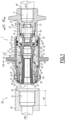
- the connecting element 1 is adapted to be removably coupled with a terminal, such as terminals 80, 80' and 80" shown respectively in figures 1 , 5 And 7 , in order to connect a fluid line 99 to the coupled terminal.
- a fitting axis, or longitudinal axis X10 is defined, which is fixed relative to the coupling body 10.
- expressions such as “axial”, “longitudinal” and “radial”, “circumferential” are defined relative to the axis X10, unless otherwise stated.
- a forward direction AV1 is defined, parallel to the axis X10, which is directed from the coupling element 1 towards the terminal to be coupled.
- a rear direction AR1 is defined, in the opposite direction.
- the expression “forward”, when it concerns the coupling element 1, is directed along the direction AV1.
- the expression “rear”, when it concerns the coupling element 1, is directed along the direction AR1.
- a radial direction is defined as a direction orthogonal and secant, that is to say perpendicular, to a longitudinal axis, here the longitudinal axis X10.
- a radial face is a face that extends around the longitudinal axis.
- a circumferential direction to a longitudinal axis is defined as a circular direction around the longitudinal axis and centered on the longitudinal axis.
- a moving point of this element moves in a circumferential direction.
- connection body 10 is connected to the fluid line 99.
- the body 10 delimits an internal conduit 11 for the fluid, which extends coaxially with the axis X10. More generally, the body 10 is centered on the axis X10 and extends along the axis X10.
- the body 10 has a shape of revolution around the axis X10.
- the terminals 80, 80' and 80" are identical, except for their interface diameter mentioned below and possibly for their interface length. Therefore, any characteristic indicated for one of the terminals 80, 80' and 80" applies to the others, unless otherwise stated.
- the terminal 80 comprises a terminal body 82, which is tubular, for conducting the circulation of fluid F.
- a central axis X82 is defined, with which the body 82 is coaxial and which is fixed relative to the body 82.
- the body 82 forms an interface 81.
- this interface 81 is internal, being formed on the inside of the body 82.
- the interface 81 has a cylindrical envelope centered on the axis X82.
- the interface 81 opens onto a front face 83 of the terminal 80.
- the interface 81 is advantageously coaxial with the axis X10.
- Expressions such as “axial”, “longitudinal” and “radial” may also be defined relative to the X82 axis when they relate to the terminal 80, unless otherwise stated.
- the expression “front”, when it relates to the terminal 80, is directed in the opposite direction to the direction AV1.
- the expression “rear”, when it relates to the terminal 80, is in the same direction as the direction AV1 of the element 1.
- the interface 81 extends over an interface length L81, measured longitudinally. From one terminal 80, 80', 80" to another, the diameter of the interface 81, called the "interface diameter", differs.
- the interface diameter of the terminal 80' of the figure 5 has a minimum value.
- the interface diameter of the 80" terminal of the figure 7 has a maximum value.
- the interface diameter of the terminal 80 of the figures 1 And 3 has an intermediate value between the minimum and maximum values. Despite this different diameter, the terminals 80, 80' and 80" can all be mated with the connecting element 1.
- the interface diameter of the terminal 80" is the maximum allowable for the connecting element 1 of the present example.
- the interface diameter of the terminal 80' is the minimum allowable for the connecting element 1 of the present example. In the following, any terminal, regardless of its interface diameter, is designated by the reference 80, unless specifically mentioned.
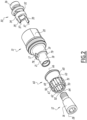
- the connecting body 10 here comprises a front part 12, an intermediate part 13 and a rear part 14 assembled.
- the intermediate part 13 and the rear part 14 are screwed together, with the interposition of a sealing gasket 15.
- the front part 12 is screwed into the intermediate part 13.
- the parts 12 and 13, or the parts 12 and 14, or the parts 13 and 14, or the parts 12, 13 and 14, could be assembled differently or formed by a single piece.
- connection body 10 is connected to the pipe 99 via the rear part 14, the pipe 99 here being received coaxially with the axis X10 inside the rear part 14, for example by being fixed there by screwing, so as to open into the internal conduit 11.
- the coupling body 10 comprises a conical front portion 16, here formed by the external radial surface of the front part 12.
- the conical portion 16 is arranged in the front direction AV1 relative to the intermediate portion 13.
- the conical portion 16 is centered on the fitting axis X10 and faces outwards.
- the conical portion 16 diverges in the front direction AV1, i.e. moves away from the axis X10 in the front direction AV1.
- the conical portion 16 is rotated in the rear direction AR1.
- the conical portion 16 defines a half-angle opening A16 measuring between 3 and 10 degrees, preferably 5 degrees.
- the half-angle A16 is the angle that the conical portion 16 makes with respect to the X10 axis. This half-angle A16 is constant over the entire length of the conical portion 16.
- the intermediate part 13 comprises, successively in the opposite direction to the direction AV1, portions 18, 19 and 20 of different diameters.
- the intermediate part 13 is connected to the front part 12 via the portion 18, here by screwing.
- the intermediate part 13 is connected to the rear part 14 via the portion 20, here by screwing.
- the portion 18 here has a smaller internal diameter than the portion 19 and the portion 19 a smaller internal diameter than the portion 20.
- the portion 18 here has a smaller external diameter than the portion 19 and the portion 19 a smaller external diameter than the portion 20.
- the intermediate part 13 is pierced with two lights 17, that is to say two openings.
- the sleeve body 60 is mounted around the internal conduit 11, around an external radial surface 21 of the body of the connector 10, at least partially around the conical portion 16.
- the external radial surface 21 is delimited by the external radial surfaces of the intermediate part 13 and of the front part 12.
- the sleeve body 60 is arranged in an interior volume 71.
- the interior volume 71 is delimited radially towards the inside by the body of the connector 10, in particular its external radial surface 21 and its conical portion 16, and, radially towards the outside, by the support ring 70.
- the sleeve body 60 is movable in translation relative to the body 10, along the axis X10, inside the interior volume 71.
- the external radial surface 21 radially guides the sleeve body 60 during its longitudinal movement relative to the body 10. More generally, the lights 17 are arranged through the connecting body 10 so as to open into the internal conduit 11 and into the internal volume 71. In other words, each light 17 connects the internal volume 71 and the internal conduit 11.
- the connecting element 1 comprises a first spring 61, which constitutes an elastic return member and which applies an elastic force recalling the socket body 60 in the forward direction AV1.
- the first spring 61 is advantageously a compression spring, which is interposed longitudinally between the connecting body 10, for example the intermediate part 13, and the socket body 60.
- the sleeve body 60 delimits housings 62. As many housings 62 are provided as there are clamping pads 50, here eight housings 62 and eight clamping pads 50. Each housing 62 receives one of the clamping pads 50. Each housing 62 has a rectangular section. Each housing 62 passes radially through the sleeve body 60. Each housing 62 opens out, towards the inside, at the height of the conical portion 16. The pads 50, and therefore their housings 62, are regularly distributed around the axis X10.
- the pads 50 being received in their respective housing 62, they are integrally movable with the sleeve body 60, for translation along the axis X10 relative to the body 10.
- the clamping pads 50 are movable relative to the sleeve body 60, in their respective housing 62, radially relative to the axis X10.
- the sleeve body 60 comprises two parallel orthoradial walls 69, visible in particular on the figure 6 , which circumferentially delimit the housing 62 and two parallel axial walls 67 and 68, which longitudinally delimit the housing 62. These walls 67, 68 and 69 guide the radial movement of the pads 50 relative to the sleeve body 60.
- Each of the axial walls 67 and 68 is able to come into contact with the pads 50 parallel to the axis X10, so that the axial position of the pads 50 corresponds to the axial position of the sleeve body 60.
- Each of the orthoradial walls 69 is able to come into contact with the pads 50 to guide the radial movement of the pads 50.
- Each clamping pad 50 is in contact with the conical portion 16.
- the radial displacement of the pads 50 is limited by the conical portion 16, which imposes on the pads 50 a radial displacement outwards as the pads 50 are moved axially in the forward direction AV1.
- the pads 50 are moved in radial translation relative to the sleeve body 60 by mechanical cooperation of the pads 50 with the conical portion 16.
- the clamping pads 50 are driven by a longitudinal movement and a radial movement in contact with the conical portion 16 between an initial position, or stop position, in the uncoupled configuration of the connection element and a retracted position then between the retracted position and a clamping position.
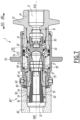
- the clamping pads 50 are movable relative to the socket body 60 between internal radial retracted positions, one of which is shown in the figure 3 , and external radial clamping positions, two of which are shown in the figures 5 And 7 , and which depend on the interface diameter of the terminal 80 which is coupled with the connecting element 1.
- the connecting element 1 When the pads 50 are in the radial withdrawal position, the connecting element 1 is in a withdrawal configuration.
- the pads 50 are in one of the radial clamping positions and cooperate with the terminal 80, the connecting element 1 is in the coupled configuration. From their radial withdrawal position to their radial clamping position, the pads 50 cooperate with the connecting body 10 by contact with the conical portion 16.
- each clamping shoe 50 comprises an internal heel 52, with a conical internal surface of a shape complementary to the conical portion 16 of the connector body 10.
- the internal heel 52 is arranged radially inwards relative to the sleeve body 60.
- the internal heel 52 is arranged in a housing, delimited by the sleeve body 60 and within from which the conical portion 16 extends, the sleeve body 60 being annular.
- the longitudinal dimension of the internal heel 52 is longer than the longitudinal dimension of the housing 62 receiving the pad 50, so that the internal heel 52 cooperates with an internal stop surface 64 of the sleeve body 60, the internal stop surface 64 delimiting the housing of the sleeve body 60 and radially facing the conical portion 16.
- the internal heel 52 and the internal stop surface 64 form a stop for the radial outward movement of the pad 50 in its housing 62.
- the pad 50 thus comes to a stop when it reaches an external radial position called the "initial radial position" or "radial stop position", adopted for an uncoupled configuration of the connecting element 1, shown in the figure figure 1 .
- the sleeve body 60 has an outer radial surface 63 that is radially turned away from the inner abutment surface 64.
- the housings 62 radially pass through the sleeve body 60 from the outer radial surface 63 to the inner radial surface 64.
- the outer radial surface 63 has a diameter smaller than the diameter of the inner interface 81 belonging to the terminal 80.
- Each clamping pad 50 has an outer surface 51 with a cylindrical shell, visible in particular on the figures 1 , 3 , 5 And 6 .
- Each external surface 51 is oriented in a radial direction opposite the internal heel 52, and therefore to the conical portion 16.
- the clamping pad 50 is designed to mechanically cooperate with the internal interface 81, which has a cylindrical envelope complementary to the external surface 51.
- the interface 81 and/or the external surface 51 may carry a respective thread complementary to each other.
- the interface 81 and/or the external surface 51 may have a surface treatment, obtained for example by laser grooving, thus increasing their mutual coefficient of friction.
- each pad 50 emerges from the socket body 60 radially outwards.
- each pad 50 has a front face 53, i.e. facing in the forward direction AV1, and a portion of which emerges radially from the socket body 60, in this uncoupled configuration.
- a portion of the front face 53 emerges radially from the external surface 63 of the socket body 60 arranged in front of the pads 50.
- the emerging portion of the front face 53 of each pad 50 faces a mouth 23 of the connecting element, parallel to the axis X10.
- each front face 53 delimits the external surface 51 in the forward direction AV1.
- the cylindrical outer surfaces 51 of the shoes 50 together delimit around the shoes 50 a virtual cylinder, the diameter of which is greater than the diameter of the external surface 63 of the sleeve body 60, in front of the shoes 50.
- the diameter of the virtual cylinder is then also greater than the maximum interface diameter of the internal interface 81.
- the socket body 60 advantageously protrudes forward of the body 10.
- the movement of the socket body 60 in the rear direction AR1 is limited by the coupling body 10.
- the socket body 60 for example comes into abutment in the rear direction AR1 against a front surface 79 of the body 10, located longitudinally at the height of the slots 17, here at the junction between the portions 18 and 19.
- this abutment is carried out by means of a rear surface 66 belonging to the socket body 60.
- the lights 17 communicate radially the internal conduit 11 and the internal volume 71 arranged radially between the connection body 10 and the support ring and in which is housed at least the rear part of the sleeve body 60.
- the lights 17 communicate in the longitudinal direction the internal conduit 11 and the internal volume 71.
- a maximum grip length L28 measured between a front face 28 of the front portion 12 of the body 10 and a rear end of the cylindrical outer surface 51 of the pads 50, when the socket body 60 is in rear abutment against the connector body 10, which happens when the connector element 1 is in the retracted configuration, is compatible with the internal dimensions of the terminal, and in particular of the interface 81.
- the front face 28 is formed in particular at the front of the conical portion 16.
- the support ring 70 is an external ring that surrounds the socket body 60, the pads 50 and the coupling body 10.
- the support ring 70 is movable in translation relative to the coupling body 10 and relative to the socket body 60 along the fitting axis X10.
- a seal 72 is interposed between an external surface of the coupling body 10, here at the front of the portion 20 of the intermediate part 13, and an internal radial face 73 of the support ring 70.
- the seal 72 is interposed between the body 10 and the ring 70 in all longitudinal positions taken by the support ring 70 relative to the body 10 during coupling and uncoupling. In other words, the support ring 70 is radially sealed with the body 10.
- a front seal 74 At a front end of the support ring 70 is housed.
- the backing ring 70 includes a rear inner surface 75 and the sleeve body 60 includes a front surface 65, formed on an outer shoulder of the sleeve body 60.
- the rear internal surface 75 is able to mechanically cooperate with the front surface 65 to drive the sleeve body 60 in the rear direction AR1, towards its axial withdrawal position, and therefore to drive the pads 50 in the rear direction AR1, so that the pads 50 adopt their internal radial withdrawal position by cooperation with the conical portion 16, the internal radial withdrawal position corresponding to the axial withdrawal position of the sleeve body 60 and the pads 50.
- the connecting element 1 comprises a second spring 76, which applies an elastic return force to the support ring 70 in the forward direction AV1 to return the ring 70 in the forward direction AV1.
- the spring 76 is a compression spring, which is interposed longitudinally between the connecting body 10 and the support ring 70.
- the spring 76 is arranged inside the ring 70 around the first spring 61.
- the connecting body 10, for example the intermediate part 13, forms a stop 24 for the movement of the support ring 70 in the forward direction AV1, when the connecting element 1 is in the uncoupled configuration as shown in the figure 1 .
- the valve 30 is mounted to move longitudinally, relative to the connection body 10, between a forward closing position, shown in the figure 1 and adopted in the uncoupled configuration of the connecting element, and the rear opening positions, shown in the figures 3 , 5 And 7 and adopted in particular in the coupled configuration of the connecting element 1.
- the valve 30 is received in the internal conduit 11.
- the connecting element 1 comprises a third spring 31, which returns the valve 30 in the forward direction AV1.
- the third spring 31 is a compression spring, which is interposed axially between the valve 30 and the body 10, in particular the rear part 14.
- the valve 30 comprises a solid central portion 32.
- the solid central portion 32 delimits, with the internal conduit 11, a passage 27 for the fluid F.
- the passage 27 is minimal and more reduced than in the rear opening position of the valve 30 in the coupled configuration.
- the valve 30 comes to bear on a seat 25 formed by the connection body 10, behind the ports 17. This bearing closes the passage 27.
- the seat 25 is formed at a junction between the portion 19 and the portion 20 of the intermediate part 13.
- This bearing of the valve 30 against the connection body 10 is carried out by means of a seal 33 between the valve 30 and the body 10, so that the closure of the passage 27 and therefore of the internal conduit 11 is watertight.
- the seal 33 is carried by the valve 30, being housed in the solid central portion 32, and comes to bear against the seat 25.
- the fluid F can pass through the internal conduit 11 around the solid portion 32 of the valve 30.
- the valve 30 comprises a front skirt 34.
- the front skirt 34 extends in the front direction AV1 from the solid central portion 32.
- the valve 30 comprises a rear skirt 36 extends in the rear direction AR1 from the solid central portion 32.
- the movement of the valve 30 relative to the body 10 is ensured by sliding of the valve 30 within the body 10.
- an external radial surface of the front skirt 34 cooperates with reduced radial clearance with a cylindrical internal surface 26 of the connection body and an external radial surface of the rear skirt 36 cooperates with reduced radial clearance with a cylindrical internal surface 29 of the connection body 10 for the radial guidance of the valve 30 in its longitudinal movement between the front position and the rear position.
- the internal radial surfaces 26 and 29 are advantageously centered on the axis X10.
- the internal radial surface 26 is advantageously formed by the portion 19 of the part 13.
- the internal radial surface 29 is advantageously formed by the rear part 14.
- the third spring 31 is interposed between a rear surface of the rear skirt 36 of the valve 30 and a front surface of the rear part 14 of the connection body 10, here arranged in the internal conduit 11.
- the front skirt 34 extends into two longitudinal legs 35, which extend parallel to the axis X10 towards the front, which are distributed at 180° from each other around the axis X10 and which form a front end of the valve 30.
- the longitudinal legs 35 are engaged in the slots 17 of the connection body 10, at least when the connection element 1 is in the coupled configuration.
- the legs 35 therefore extend partially into the interior volume 71.
- the legs 35 longitudinally pass through the slots 17 from the interior volume 71 into the internal duct 11, where the legs are attached to the front skirt 34.
- the circumferential dimensions of the slots 17 of the connecting body 10 correspond to the circumferential dimensions of the longitudinal legs 35.
- each leg 35 between the uncoupled configuration and the coupled configuration is guided by facing guide surfaces 78, here orthoradial and parallel, visible on the figure 4 and capable of coming into contact with the tab 35.
- These guide surfaces 78 belong to the connection body 10 and circumferentially delimit the light 17, in which the tab 35 is engaged.
- the longitudinal legs 35 each have a respective front end surface 37.
- the front end surfaces 37 are directed in the front direction AV1, opposite the rear surface 66 belonging to the socket body 60.
- the rear surface 66 precisely forms a rear end of the socket body 60.
- the valve 30 is in the front closing position, in front abutment against the body 10 via the seal 33, and a longitudinal clearance J35 exists between the front end surfaces 37 of the longitudinal legs 35 and the rear surface 66 of the socket body 60.
- the legs are longitudinally disengaged from the socket body and the pads.
- the longitudinal legs 35 constitute transmission means, which are interposed between the valve 30 and the sleeve body 60.
- the transmission means are directly formed by the valve 30, namely by the legs 35.
- An advantage is that the direct axial mechanical cooperation between the sleeve body 60 and the valve 30, obtained when the transmission means are in one piece either with the sleeve body 60 or with the valve 30 as is the case here, makes it possible to reduce the number of parts of the connection element 1. Indeed, it is advantageously not necessary to provide additional parts to specifically constitute the transmission means.
- the longitudinal geometry of the transmission means here in the form of the longitudinal tabs 35, reduces the longitudinal dimensions of the slots 17 made in the connection body 10. In fact, the longitudinal dimensions do not depend on the stroke and the movement of the valve 30 relative to the connection body 10. This gives better mechanical strength to the connection body 10.
- the first spring 61 is arranged radially around the longitudinal legs 35 of the valve 30 and around the intermediate part 13 of the connection body 10.
- the first spring 61 surrounds the rear end of the sleeve body 60.
- the first spring 61 is radially guided by the sleeve body 60 and by the intermediate part 13.
- the terminal 80 and the connecting element 1 are arranged to align the axes X10 and X82.
- the connecting element 1 is in the uncoupled configuration, as shown in the figure 1 .
- connection body 10 and the terminal 80 are then brought closer together along the fitting axis X10.
- the terminal 80 engages around the sleeve body 60 and its front face 83 comes into contact with the front seal 74 of the support ring 70.
- the front seal 74 then ensures, with the radial seal 72, a fluid seal between the inside and the outside of an assembly formed by the connection element 1 and the terminal 80.
- the front face 83 also comes bearing against the emerged part of the front face 53 of the pads 50.
- the pads 50 move radially inwards, towards their radial withdrawal position, in their respective housing 62, until the pads 50 are arranged inside a virtual cylinder, the diameter of which is less than the diameter of the internal interface 81.
- the terminal 80 can then come to surround the pads 50, without rubbing, or with little rubbing, and progressing in the rear direction AR1 relative to the pads 50 and the connecting body 10, until the support ring 70 comes into abutment against the front surface 65 of the sleeve body 60.
- the connecting element 1 is in a retracted configuration.
- the pads 50 reach their radial retracted position which is radially distant from the interface 81 so that the interface 81 is free from any mechanical cooperation with the pads 50.
- the first spring 61 pushes the socket body 60 in the direction AV1, in front abutment against the pads 50, via the wall 68.
- the pads 50 by mechanical cooperation with the conical portion 16, are pressed radially outwards in contact with the interface 81 of the terminal 80, which is radially opposite the external surface 51 of the pads 50.
- the clamping pads 50 cooperate with the socket body 60 in their radial outward movement from the retracted position to the clamping position, the first spring 61 pushing the socket body 60 into a forward abutment against the pads 50 between the retracted configuration of the connecting element 1 and the coupled configuration of the connecting element 1 and into the coupled configuration of the connecting element 1.
- the longitudinal legs 35 form the transmission means, which are integral with the valve 30 and integral with the valve 30.
- These transmission means allow the sleeve body 60 to drive the valve 30 from its front position to its rear position, between the uncoupled configuration and the coupled configuration of the connecting element 1.
- these transmission means are received at least partially in the slots 17, which allows the transmission of the movement between the sleeve body 60, arranged around the body 10, to the valve 30, arranged, for the most part, inside the body 10.
- the valve 30 follows this forward movement, itself pushed into a front stop against the rear surface 66 of the socket body 60 by the third spring 31, until reaching the open position during coupling or until reaching the forward closing position during uncoupling.
- the valve 30 in the coupled configuration, has a position offset in the rear direction AR1 relative to its front closing position and the passage 27, which was minimal between the connection body 10 and the valve 30 in the internal conduit 11 so as to be able to be closed by the seal 33 in the uncoupled configuration, as shown in the figure 1 , is increased.
- the internal volume 71 communicates fluidically with the internal conduit 11 through the ports 17. The internal volume 71 is therefore subjected to the pressure of the fluid F present in the internal conduit 11.
- a sealing diameter between the support ring 70 and the terminal 80, here at the level of the front seal 74, is smaller than a sealing diameter between the internal radial face 73 of the support ring 70 and the connection body 10, here at the level of the seal 72, the support ring 70 is pushed back in the forward direction AV1 relative to the connection body 10, against the terminal 80, which accentuates the sealing of the front seal 74 against the terminal 80.
- the longitudinal legs 35 are engaged longitudinally with the sleeve body 60 and with the valve 30.
- the interface 81 at least partially covers the pads 50 and the pads 50 mechanically cooperate with the interface 81 so as to prevent the withdrawal of the terminal 80, that is to say so as to prevent the interface 81 from completely uncovering the pads 50.
- the sleeve body 60 is held in the axial clamping position, in abutment towards the front against the pads 50 via the wall 68, by the first spring 61.
- the tabs 35 extend longitudinally in the slots 17 from the interior volume 71 into the internal conduit 11.
- the terminal 80 is first pushed further in the rear direction AR1 of the connecting element 1.
- the support ring 70 is driven in the rear direction AR1 relative to the body 10, such that the support ring 70 comes into rear abutment against the sleeve body 60 and thus drives the sleeve body 60 into rear abutment against the pads 50, via the wall 67.
- the pads 50 are thus driven in the rear direction AR1 by the sleeve body 60.
- the support ring 70 then forms an operating ring.
- the same ring 70 here forms both the support ring and the operating ring.
- the pads 50 follow the axial movement of the support ring 70 in the rear direction AR1 of the sleeve body 60, and, by mechanical cooperation with the conical part 16, move radially inwards towards their radial withdrawal position, until the pads 50 are arranged inside a virtual cylinder, the diameter of which is less than the interface diameter 81.
- the pads 50 are radially distant from the interface 81, while the interface 81 surrounds them.
- the interface 81 is then released from any mechanical cooperation with the pads 50, so that the terminal 80 can be removed from the connection element 1, that is to say, can completely uncover the external radial surface 51 of the pads 50.
- the clamping pads 50 cooperate with the socket body 60 in their radial movement towards the inside, from the clamping position to the withdrawal position, the socket body 60 then being in rear abutment against the pads 50.
- valve 30 From the uncoupled configuration to the coupled configuration and/or from the coupled configuration to the uncoupled configuration, the valve 30 has overtraveled in the rear direction AR1 reaching the position that was temporarily taken when the connecting element 1 passed through the withdrawal configuration, for example the withdrawal configuration shown in FIG. figure 3
- the valve 30 travels a stroke C30, called the “maximum stroke”, of the uncoupled configuration shown in the figure 1 to the withdrawal configuration with the socket body 60 in rear abutment against the body 10 shown in the figure 3 .
- the valve 30 performs a movement L30, from the uncoupled configuration of the figure 1 to the coupled configuration, for example that figure 7 with the 80" terminal whose interface diameter is maximum.
- the maximum stroke C30 is strictly greater than the displacement L30.
- the maximum stroke C30 for any 80 terminal and the displacement L30 with the 80" terminal of maximum interface diameter are strictly greater than a length L17 of the ports 17.
- the length L17 is the smallest distance, taken parallel to the X10 axis between two front and rear axial surfaces delimiting each port 17.
- the radial clamping position of the pads 50 is an intermediate radial position between the initial radial position and the radial withdrawal position, in particular the radial withdrawal position with the sleeve body 60 in rear abutment against the body 10.
- the sleeve body 60 and the pads 50 are movable longitudinally relative to the connection body 10 respectively between an initial front position, called the “axial abutment position”, shown in FIG.
- FIG 1 corresponding to the uncoupled configuration, an intermediate position, moved back along the X10 axis relative to the initial position, called the “axial clamping position”, which depends on the interface diameter, corresponding to the coupled configuration, and a rear position, called the “axial withdrawal position”, in particular the axial withdrawal position shown in the figure 3 with the socket body 60 in rear abutment against the body 10.
- Another example of axial clamping position, corresponding to a maximum interface diameter, is shown in the figure 7 .
- the larger the interface diameter the more advanced the axial clamping position of the sleeve body 60 and the pads 50.
- the cooperation surface 51 of each pad 50 in the clamping position is in a position offset radially inward and offset longitudinally in the rear direction AR11.
- the longitudinal clearance J35 preferably remains less than or equal to 20% of the maximum stroke C30, in particular less than or equal to 15% of the maximum stroke C30.
- the invention provides that the transmission means are interposed between the valve 30 and a drive element, among the sleeve body 60 and at least one of the clamping pads 50, so that this drive element can drive the valve 30 via the transmission means, from the front position to a rear position, where the valve opens the internal conduit, when the connection element 1 passes from the uncoupled configuration to the coupled configuration.
- the pads have longitudinal legs which come to bear against the valve to push it back.
- the longitudinal legs are then driven by a longitudinal movement and a radial movement between the stop position and the withdrawal position and between the withdrawal position and the clamping position.
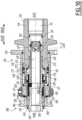
- THE figures 8 to 10 show a connecting element 101, to be connected to a terminal 80, according to another embodiment. Except for the main differences mentioned below, the connecting element 101 and the terminal 80 are similar in structure and operation to the connecting element 1 and the terminal 80, and are intended for similar use.
- the connecting element 101 comprises a connecting body 110, a valve 130, clamping pads 150, a sleeve body 160 and a support ring 170.
- the valve 130 and the sleeve body 160 are distinct.
- a fitting axis X110 is defined which is fixed relative to the connection body 110 and on which the connection body 110 is centered.
- a forward direction AV101 is defined, parallel to the axis X110, which is directed from the connection element 1 towards the terminal to be coupled.
- a rear direction AR1 is defined, in the opposite direction.
- the terminal 180 comprises a terminal body 182, which is tubular, for conducting the circulation of fluid.
- a central axis X182 is defined, with which the body 182 is coaxial and which is fixed relative to the body 182.
- the body 182 forms an interface 181.
- this interface surface 181 is internal.
- the interface 181 has a cylindrical envelope centered on the axis X182.
- the interface 181 opens onto a front face 183 of the terminal 180.
- the interface 181 is advantageously coaxial with the axis X110.
- the connecting body 110 formed here by only two assembled parts, namely a part forming a rear part 114, and a part forming both a front part 112 and an intermediate part 113.
- the body 110 delimits an internal conduit 111 for the circulation of the fluid, the internal conduit 111 passing through the parts 112, 113 and 114 along the axis X110.
- the rear portion 114 is intended to be connected to a fluid line similar to the line 99 illustrated for the embodiment of the Figures 1 to 7 and is fixed to the part forming parts 112 and 113, for example by screwing, via part 113.
- the front part 112 forms a conical front portion 116, which is centered on the axis X110, diverging in the direction AV101 and facing outwards.
- the front part 112 and the intermediate part 113 together form an external radial surface 121 of the connection body 110.
- An internal volume 171 is delimited radially between the support ring 170 and the external radial surface 121.
- connection body 110 Three ports 117, regularly distributed around the axis X110, are provided through the connection body 110, here through the intermediate part 113.
- the ports 117 open both into the internal conduit 111 and into the internal volume 171, at the level of the external radial surface 121 of the connection body 110.
- the internal volume 171 communicates fluidically with the internal conduit 111 through the ports 117, in particular when the connection element is in the coupled configuration.
- the socket body 160 is arranged around the external radial surface 121 of the connection body 110.
- the socket body 160 is movable in translation along the axis X110 relative to the connection body 110.
- the sleeve body 160 has an internal radial surface 164, radially facing the conical portion 116, an external radial surface 163, as well as radial housings 162, which connect the surfaces 163 and 164 and which are regularly distributed around the axis X110.
- Each housing 162 receives one of the clamping pads 150.
- Each housing 162 has two parallel axial walls and two parallel orthoradial walls, similarly to the housings 62, to guide a radial movement of the clamping pads 150.
- Each clamping shoe 150 has an external surface 151 with a cylindrical envelope.
- the pads 150 upon coupling, are radially movable relative to the sleeve body 160 and relative to the body 110, from an initial radial position, shown in the figure 8 , to a radial clamping position shown on the figure 10 , passing through a radial stop position, not illustrated.
- the radial displacement of the pads 150 is obtained by mechanical cooperation of a respective internal heel 152, with which each pad 150 is provided, with the conical portion 116 of the connection body 110, when the pads 150 and the sleeve body 160 translate along the axis X110.
- the pads 150 are in the radial stop position, shown in the figure 8 .
- the pads 150 are in external radial abutment against the internal abutment surface 164 of the sleeve body 160, via their respective heel 152.
- the 150 skates have a 153 front face. As shown in the figure 8 , in the uncoupled configuration of the connecting element 101, a portion of the front face 153 emerges radially from the socket body 160 from the outer surface 163 in front of the pads 150 and, thus, axially faces a mouth 123 of the connecting element 101.
- the cylindrical outer surfaces 151 of the pads 150 together delimit a virtual cylinder, the diameter of which is greater than the diameter of the outer surface 163 of the socket body 160, in front of the pads 150.
- the diameter of the virtual cylinder is also greater than the diameter of the internal interface 181.
- the external radial clamping position shown in the figure 10 is obtained when the connecting element 101 is in a coupled configuration, and is coupled with the terminal 180.
- the clamping pads 150 mechanically cooperate with the interface 181 of the terminal 180 and thus prevent removal of the terminal 180 when the connecting element 101 is in a coupled configuration.
- the sleeve body 160 is in an axial clamping position, where the sleeve body 160 abuts against the pads 150 in the direction AV101.
- the connecting element 101 comprises an elastic return member 161, namely a spring, returning the sleeve body 160 forward, in particular towards an axial clamping position.
- the clamping pad 150 is designed to mechanically cooperate with the internal interface 181 when the connecting element 101 is in the coupled configuration.
- the interface 181 has a cylindrical envelope complementary to that of the external surfaces 151.
- the pads 150 retain the coupled terminal 180 via their surface 151.
- the clamping pads 150 When the connecting element 101 is placed in the retracted configuration while the connecting element 101 was in the coupled configuration and was coupled with the terminal 180, the clamping pads 150 reach their radially inner retracted position. In this radially retracted position, the pads 150, in particular their outer surface 151, are radially disengaged inwardly from the interface 181 of the terminal 180, thereby allowing the terminal 180 to be withdrawn from the body 110.
- the valve 130 is arranged inside the body 110, in particular inside the part 113.
- the valve 130 is movable in translation relative to the connection body 110 in the internal conduit 111. Under the action of a spring 131, the valve 130 is elastically returned to a front position, where the valve 130 closes the internal conduit 111. This front position of the valve 130 is obtained for the uncoupled configuration of the connection element shown in FIG. figure 8 . In the coupled configuration, the valve 130 is in a rear position to open the conduit 111.
- valve 130 comprises a solid central portion 132 and a front skirt 134. Unlike the embodiment of the Figures 1 to 7 , no rear skirt is provided. In other words, the valve 130 is guided radially at a single zone, here via the front skirt 134, and not two axially spaced zones, as is the case for the valve 30, which is guided by the skirts 34 and 36.
- the solid central portion 132 delimits, with the internal conduit 111, in particular at the height of the part 114 of the body 110, a passage 127 for the fluid.
- the passage 127 is smaller than for the coupled configuration, where the valve 130 is in the rear position, as shown in the figure 10 .
- the reduction of the passage 127 causes the conduit 111 to be closed in the uncoupled configuration, compared to the coupled configuration where the conduit 111 is open.
- a seal 133 is provided to close the passage 127 when the valve 130 is in the front position.
- the seal 133 is advantageously carried by the solid central portion 132 and comes to bear against the rear part 114 when the valve 130 is in the front position, to close the conduit 111.
- the front skirt 134 mechanically cooperates with reduced radial clearance with an internal radial surface 126 of the connection body 110, for the radial guidance of the movement of the valve 130 between the uncoupled configuration and the coupled configuration of the connection element.
- the internal radial surface 126 delimits a portion of the internal conduit 111.
- the internal radial surface 126 is formed jointly by the intermediate portion 13 and the rear portion 114.
- the support ring 170 is mounted so as to, in the uncoupled configuration, be arranged around the socket body 160 and the pads 150, as shown in the figure 8 .
- the support ring 170 is external to the connection body 110.
- the support ring 170 is radially sealed with the connection body 110.
- a seal 172 is provided here, interposed between the rear part 114 and an internal radial face 173 of the support ring 170.
- the internal radial face 173 also delimits the internal volume 171.
- the support ring 170 comprises a front seal 174, which comes into axial contact with the front face 183 of the terminal 180, to provide axial sealing between the terminal 180 and the support ring 170, in particular in the coupled configuration, but also during coupling.
- the connecting element 101 comprises a spring 176, which applies an elastic return force to the support ring 170 in the forward direction AV101 to return the ring 170 in the forward direction AV101 relative to the body 110.
- the spring 176 is a compression spring interposed longitudinally between the connecting body 110 and the support ring 170.
- the spring 176 is arranged inside the ring 70 around the spring 161.
- the support ring 170 serves as an operating ring, operable by a technician to place the connecting element 101 in the retracted configuration, while the connecting element 101 was in the coupled configuration and was coupled with the terminal 180.
- a single ring 170 serves as both a support ring and an operating ring.
- the support ring 170 is adapted to drive the pads 150 from the radial clamping position to the radial retracted position, in that the support ring 170 drives the sleeve body 160 from the axial clamping position to the axial retracted position, when the support ring 170 is moved to its rear position.
- a rear inner surface 175 of the support ring 170 comes to bear rearwardly against a front surface 165 of the socket body 160, the support ring 170 thus driving the socket body 160 rearwardly.
- the connecting element 101 comprises a transmission ring 135, which is distinct from the valve 130, the sleeve body 160 and the pads 150, and which provides a transmission means function, by being interposed longitudinally between the valve 130 and one of the sleeve body 160 and the pads 150.
- the transmission ring 135 is interposed between the valve 130 and the pads 150, and not between the valve 130 and the sleeve body 160. In practice, the transmission ring 135 is mounted loosely between the pads 150 and the valve 130.
- the transmission ring 135 being thus interposed between the pads 150 and the valve 130, the pads 150 drive the valve 130, from the front position to the rear position by means of the transmission ring 135, when the connection element 101 evolves from the uncoupled configuration to the coupled configuration.
- the transmission ring 135 comprises a ring body 140, which extends around the body 110, in particular around the front part 112 and the intermediate part 113, and comprises pins 141, which are carried on the inside of the ring body 140, and project radially inwards, so as to pass through the slots 117.
- Each pin 141 thus extends from the volume 171 to the duct 111, whereas the ring body 140 extends only into the volume 171 without reaching the duct 111.
- the transmission means pass through the lights 117, in particular in coupled configuration.
- the elastic return member 161 is arranged radially on the outside relative to the transmission means, in particular relative to the ring body 140.
- the transmission ring 135 has a front surface 137, which comes into contact with the pads 150.
- the front surface 137 is formed by the ring body 140.
- each pad 150 comprises a respective rear surface 142, by means of which the front surface 137 comes into contact with the pads 150.
- the rear surface 142 is for example formed at the rear of the heel 152. This contacting allows the pads 150 to drive the transmission ring 135, and thus the valve 130, in the rear direction AR101.
- the transmission ring 135 also has one or more rear surfaces 138, each rear surface 138 coming into contact with the valve 130.
- each rear surface 138 is formed by one of the pins 141.
- the valve 130 comprises a front surface 139, formed at the front of the skirt 134, by means of which the rear surfaces 138 come into contact with the valve 130.
- the longitudinal dimension of the slots 117 is greater than the displacement L130 of the valve 130 between the uncoupled configuration and the coupled configuration.
- the displacement L130 is measured parallel to the axis X110.
- the transmission means are longitudinally disengaged from the pads 150 and/or the valve 130, providing a longitudinal clearance J135 between, on the one hand, the transmission ring 135 and, on the other hand, the pads 150 and/or the valve 130.
- the clearance J135 is shown between the transmission ring 135 and the pads 150, in particular between the front surface 137 and the rear surface 142, while the rear surface(s) 138 of the transmission ring 135 are in contact with the valve 130.
- the rear surface 142 of the pads 150 comes into contact with the front surface 137 of the transmission ring 135, the transmission ring 135 coming, by its rear surface(s) 138, into contact with the front surface 139 of the valve 130, to allow the pads 150 to drive the valve 130 from its front position to its rear position, between the uncoupled configuration and the coupled configuration.
- the transmission ring 135 is designed as a single piece. However, in practice, for mounting the transmission ring 135 around the body 110, in particular when the body 110 itself consists of two assembled parts as here, the transmission ring 135 can be made up of several assembled parts.
- the rear surface(s) 138 of the transmission ring 135 are formed on pins and/or lugs which are longitudinal, rather than radial like the pins 141 illustrated, in order to reduce the longitudinal dimension of the corresponding slots 117.
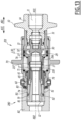
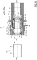
- FIGS 11 to 13 show a connecting element 201, to be connected to a terminal 280, according to another embodiment.
- the terminal 280 is identical to the terminal 80.
- the connecting element 201 is identical to the connecting element 1, except for the differences mentioned below. All the features already described above for the connecting element 1 and the terminal 80 apply to the element 201 and the terminal 280, except for the differences mentioned below, and are designated by the same reference signs in the Figures 11 to 13 that on the Figures 1 to 7 .
- the connecting element 201 is in the uncoupled configuration.
- the connecting element 201 is in a coupled configuration.
- the transmission means of the connecting element 201 are formed by the socket body 60 of the element 201.
- the socket body 60 extends for example into two longitudinal tabs 235, which extend towards the rear and form a rear end of the socket body 60.
- the valve 30 is then advantageously devoid of the tabs 35 which were provided for the connecting element 1.
- the tabs 235 are engaged in the slots 17 and pass longitudinally through these slots 17 parallel to the axis X10, from the interior volume 71 to the internal conduit 11.
- the circumferential dimensions of the slots 17 of the connecting body 10 correspond to the circumferential dimensions of the longitudinal tabs 235.
- each tab 235 is guided by surfaces parallel orthoradial, belonging to the connecting body 10 and delimiting the light 17, in which the tab 235 is engaged.
- the connecting element 201 passes from the uncoupled configuration to the coupled configuration, the sleeve body 60 drives the valve 30 via the tabs 235, from the position to the rear position, where the valve 30 opens the internal conduit 11.
- the tabs 235 therefore constitute the transmission means by which the sleeve body 60 is able to drive the valve 30 from the front closing position to the rear opening position.
- the longitudinal legs 235 each have a respective rear end surface 266.
- the rear end surfaces 266 are directed in the rear direction AR1, opposite a front surface 237 belonging to the valve 30.
- the front surface 237 is here formed at the front of the valve 30, in particular of the skirt 34.
- the valve 30 In the uncoupled configuration, the valve 30 is in the front closing position, in front abutment against the body 10, and a longitudinal clearance J235 exists between the end surfaces 237 and 266.
- the tabs 235 are longitudinally disengaged from the valve 30.
- the connecting element 1 there is a dead travel at the start of coupling, when moving the sleeve body 60 in the rear direction AR1, corresponding to the clearance J235.
- the connecting element 201 does not have the seal 33, the valve 30 of the connecting element 201 being devoid of a seal to close the passage 27. Instead, the passage 27 is reduced without being sealed when the valve 30 of the connecting element 201 is in the forward closing position, and is increased when the valve 30 is in the rear opening position.
- the solid central portion 32 of the valve 30 of the element 201 is directly in front abutment against the body 10 under the effect of the spring 31.
- the closing of the internal conduit 11 by the valve 30 is therefore not watertight in the uncoupled configuration, but the valve 30 in the forward closing position nevertheless limits the passage of fluid out of the connecting element 201. This makes it possible to limit fluid leaks in the uncoupled configuration.
- the connecting element 201 comprises housings 262, to provide the same function as the housings 62 provided for the connecting element 1.
- the housings 262 comprise an axial surface 267 which delimits the housing 262 towards the front.
- valve 30 comes into abutment against the sleeve body 60, rather than against the connector body 10, when the valve 30 is in the forward closing position. In this case, there is no longitudinal play J35 and therefore no dead travel.
- THE figures 14 And 15 show a connecting member 301, to be connected to a terminal 380, according to another embodiment. Except for the main differences mentioned below, the connecting member 301 and the terminal 380 are similar in structure and operation to the connecting member 1 and the terminal 80, and are intended for similar use.
- the connecting element 301 comprises a connecting body 310, a valve 330, clamping pads 350, a sleeve body 360, a support ring 370 and an operating ring 345.
- a fitting axis X310 which is fixed relative to the fitting body 310 and on which the fitting body 310 is centered.
- a forward direction AV301 parallel to the axis X310, which is directed from the connecting element 301 towards the terminal 380 to be coupled.
- a rear direction AR301 is defined, in the opposite direction.
- the terminal 380 comprises a terminal body 382, which is tubular, for conducting the circulation of fluid F.
- a central axis X382 is defined, with which the body 382 is coaxial and which is fixed relative to the body 382.
- the body 382 forms an interface 381.
- this interface surface 381 is external, unlike the interface 81 described above.
- the interface 381 has a cylindrical envelope centered on the axis X382.
- the interface 381 ends on a front face 383 of the terminal 380.
- the interface 381 constitutes an external thread centered on the axis X382.
- the connecting body 310 formed here by only two assembled parts, namely a part forming both an intermediate part 313 and a rear part 314, and another a part forming a front part 312.
- the body 310 delimits an internal conduit 311 for the circulation of the fluid F, the internal conduit 311 passing through the parts 312, 313 and 314 along the axis X310.
- the rear part 314 is intended to be connected to a fluid line similar to the aforementioned line 99 and is fixed to the part forming the front part 312 by screwing.
- the front part 312 forms a conical portion 316, which is centered on the axis X310, convergent along the direction AV301 and turned inwards and along the rear direction AR301.
- the intermediate portion 313 is here arranged inside the front 312 and rear 314 portions.
- the intermediate portion 313 forms an external radial surface 321 of the connecting body 310.
- the external radial surface 321 therefore faces radially the front 312 and rear 314 portions of the connecting body 310.
- An interior volume 371 is delimited, radially on the inside, by the external radial surface 321 and, radially on the outside, by the front 312 and rear 314 portions.
- the connecting element 301 comprises a slot 317, arranged through the connecting body 310.
- a blind recess formed as a hollow in an internal radial surface of the rear part 314 delimiting the conduit 311, at a junction between the rear part 314 and the intermediate part 313, houses the valve 330. From this blind recess, the slot 317 passes through the body 310 in the forward direction AV301, beyond a rear end of the intermediate part 313, so as to open into the interior volume 371.
- the slot 317 connects the blind recess of the conduit 311 to the interior volume 371.
- the slot 317 delimits the interior volume V371 on the rear.
- the valve 330 comprises a solid portion 332, which in the uncoupled configuration, is arranged at least partially inside the intermediate portion 313.
- the valve 330 also comprises radial bridges 334, which extend radially outward from the solid portion 332 to the blind recess of the body 310.
- the sleeve body 360 is arranged around the external radial surface 321 of the connector body 310, inside the interior volume 371.
- the sleeve body 360 is mounted around the support ring 370, itself arranged around the external radial surface 321 of the connector body 310.
- valve 330 and the sleeve body 360 are integral with each other parallel to the axis X310 in any configuration of the connecting element 301.
- the connecting element 301 comprises a transmission ring 335, which axially connects the sleeve body 360, in particular a rear end of the sleeve body 360, to the valve 330, in particular an external radial end of the radial bridges 334.
- the transmission ring 335 passes through the light 317 when the connecting element 301 is in the coupled configuration, as shown in FIG. figure 15 .
- the transmission ring 335 thus constitutes transmission means which are interposed between the valve 330 and the sleeve body 360, being integral with both the valve 330 and the sleeve body 360.
- the sleeve body 360 and the valve 330 drive each other along the axis X310, being integral via the transmission ring 335.
- the sleeve body 360 and the valve 330 are integrally movable in translation relative to the connection body 310, along the axis X310.
- the connection element 301 does not provide for longitudinal play such as the play J35 in the uncoupled configuration.
- the valve 330, the transmission ring 335 and the sleeve body 360 may be formed by a single piece in one piece, as shown in the figures 14 And 15 or, alternatively, by several pieces assembled and secured to each other.
- the connecting element 301 comprises an elastic return member 361.
- the member 361 is preferably a compression spring interposed between the sleeve body 360 and the connecting body 310.
- the member 361 integrally pushes the sleeve body 360, the transmission ring 335 and the valve 330 in the forward direction AV301, relative to the body 310.
- a single return member 361 pushes both the sleeve body 360 and the valve 330, unlike the valve 30 described above, which is pushed by a spring 31 independent of the elastic return member 61 returning the sleeve body 60.
- the clamping pads 350 are each received in a respective housing 362, belonging to the socket body 360, to guide their movement in radial translation.
- the clamping pads 350 are moved in translation, radially relative to the socket body 360 and relative to the connector body 310, between an external radial retraction position, not illustrated, when the connector element 301 is in the retraction configuration, an intermediate radial clamping position, shown in FIG. figure 15 , when the connecting element 301 is in the coupled configuration and an internal radial abutment position, shown in the figure 14 , when the connecting element 301 is in the uncoupled configuration.
- the housings 362 comprise two facing parallel axial walls and two facing parallel orthoradial walls, which guide the radial movement of the clamping pads 350.
- each pad 350 comprises a heel 352, which, unlike the heel 52, is formed on the outside of the pad 350, the heel 352 being in contact with the conical portion 316.
- Each pad 350 also comprises an internal surface 351 with a cylindrical envelope. This internal surface 351 is oriented radially opposite the heel 352, therefore the conical portion 316.
- the clamping pad 350 is designed to cooperate mechanically with the external interface 381, which has a cylindrical envelope complementary to the surface 351.
- the internal surface 351 advantageously carries an internal thread complementary to that of the interface 381.
- the internal radial stop position of the pads 350 corresponds to a front axial position of the pads 350, of the sleeve body 360, of the transmission ring 335 and of the valve 330.
- This front axial position is adopted in the uncoupled configuration, as shown in the figure 14 .
- the pads 350 are in radial abutment via the heel 352 against an external abutment surface 364 of the sleeve body 360 radially facing the conical portion 316.
- each pad 350 emerges from the socket body 360 radially inward.
- each pad 350 has a front face 353, facing a mouth 323 of the connecting element 301.
- a portion of the front face 353 emerges radially inward from an inner surface 363 of the socket body 360 in front of the pads 350, in this uncoupled configuration, and against which the front face 383 of the terminal 380 is intended to come axially into contact at the start of the coupling, to push in the direction AR301 an assembly comprising the pads 350, the sleeve body 360 and the valve 330.
- the valve 330 closes the conduit 311.
- the solid part 332 is preferably received at least partially inside the intermediate part 313.
- the solid part 332 advantageously carries a seal 333, to ensure radial sealing between the valve 330 and the intermediate part 313, thus sealing the conduit 311.
- the valve 330 itself, in particular the solid part 332, preferably does not come into axial support against the body 310.
- the elastic return member 361 recalling the valve 330 and the sleeve body 360 in the direction AV301, it recalls the valve 330 towards this position before closing.
- the support ring 370 is mounted inside the sleeve body 360 and the pads 350.
- a rear end of the support ring 370 is preferably mounted around the intermediate part 313, that is to say around the external radial surface 321.
- the support ring 370 is movable in translation along the axis X310 relative to the body 310 and is not integral with the assembly comprising the sleeve body 360 and the valve 330.
- a seal 372 is interposed between an internal surface of the sleeve body 360, at the rear of the pads 350, and an external radial face of the support ring 370.
- a seal 377 is interposed between, on the one hand, the sleeve body 360 or the transmission ring 335 and, on the other hand, the front part 312 or the rear part 314 of the connection body 310.
- the intermediate part 313 advantageously carries a seal 390 in sliding contact with the internal radial surface of the transmission ring 335.
- the seals 377 and 390 provide a seal at the level of the light 317, between the internal conduit 311 and the internal volume 371.
- a front seal 374 intended to come into axial support against the front face 383 of the terminal 380 during coupling and in the coupled configuration.
- the connecting element comprises a spring 376 which applies an elastic return force to the support ring 370 in the forward direction AV301 to return the ring 370 in the forward direction AV301.
- the spring 376 is a compression spring, which is interposed longitudinally between the intermediate portion 313 of the connecting body 10 and the support ring 370.
- the spring 376 is arranged radially between the intermediate part 313 and the sleeve body 360 and/or the transmission ring 335.
- the intermediate radial clamping position of the pads 350 corresponds to an intermediate axial position of the pads 350, the sleeve body 360 and the valve 330.
- the cooperation surface 351 of each pad 350 in the radial clamping position is in a position offset radially outwards and offset longitudinally in the rear direction AR301.
- the pads 350 are in the intermediate radial clamping position, so as to mechanically cooperate with the interface 381 of the terminal 380, to prevent withdrawal of the terminal 380 relative to the connecting body 310.
- the sleeve body 360 is then in the axial clamping position, where the sleeve body 360 is in abutment in the forward direction AV301 against the pads 350, under the action of the elastic return member 361.
- the sleeve body 360 In front of the pads 350, the sleeve body 360 has an internal diameter greater than that of the interface 381.
- the interface 381 is received at least in part inside the sleeve body 360 in the coupled configuration.
- the sleeve body 360 opens the conduit 311 via the light 317.
- the sleeve body 360 has opened the internal conduit 311, when the connecting element 301 evolves from the uncoupled configuration to the coupled configuration.
- the solid part 332 is set back in the direction AR301 relative to the intermediate part 313.
- the flow F can circulate in the conduit 311 in particular between the rear part 314 and the intermediate part 313, passing through the valve 330, between the radial bridges 334 in the blind recess.
- the pads 350 are spaced from the interface 381, radially outward.
- the cylindrical inner surfaces 351 of the pads 150 then together delimit a virtual cylinder whose diameter is less than the minimum diameter of the external interface 381.
- the pads 350 then allow the terminal to be withdrawn in the forward direction AV301 relative to the connecting body 310.
- the external radial position of withdrawal of the pads 350 corresponds to a rear axial position of the pads 350, of the sleeve body 360 and of the valve 330.
- the operating ring 345 is formed by a ring distinct from the ring forming the support ring 370.
- the operating ring 345 is external to the connecting body 310, here surrounding the front part 312.
- the operating ring 345 is here secured to the socket body 360, for example by means of a screw 346, radially passing through the body 310 to connect the operating ring 345 to the socket body 360.
- the operating ring 345 is capable of driving the socket body 360 in the rear direction AR301 while the element 301 is in the coupled configuration, and thus putting the element 301 in the retracted configuration.
- the ring 335 is longitudinally interposed between the valve 330 and the sleeve body 360, while constituting a separate part from the sleeve body 360, from the valve 330, or from both the sleeve body 360 and the valve 330.
- This separate transmission ring can alternatively be arranged between the valve 330 and the pads 350.
Landscapes
- Engineering & Computer Science (AREA)
- General Engineering & Computer Science (AREA)
- Mechanical Engineering (AREA)
- Quick-Acting Or Multi-Walled Pipe Joints (AREA)
- Mechanical Coupling Of Light Guides (AREA)
- Connector Housings Or Holding Contact Members (AREA)
Claims (15)
- Anschlusselement (1; 101; 201; 301), für einen fluidischen Anschluss an ein Endgerät (80; 180; 280; 380), wobei das Endgerät eine Schnittstelle (81; 181; 381) mit zylindrischem Mantel aufweist, das Anschlusselement (1; 101; 201; 301) umfassend:- einen Anschlusskörper (10; 110; 310), der einen inneren Kanal (11; 111; 311) für eine Fluidzirkulation (F) begrenzt, wobei sich der innere Kanal (11; 111; 311) entlang einer Längsachse (X10; X110; X310) erstreckt,- ein Ventil (30; 130; 330), das in Längsrichtung in Bezug auf den Anschlusskörper (10; 110; 310) in dem inneren Kanal (11; 111; 311) bewegbar ist, wobei die Ventil (30; 130; 330) in einer Vorwärtsrichtung (AV1; AV101; AV301) elastisch in eine vordere Position vorgespannt ist, in der das Ventil (30; 130; 330) den inneren Kanal (11; 111; 311) in einer von dem Anschlusselement (1; 101; 201; 301) entkoppelten Konfiguration schließt, und- Klemmkufen (50; 150; 350),dadurch gekennzeichnet, dass das Anschlusselement (1; 101; 201; 301) Folgendes umfasst:- einen Hülsenkörper (60; 160; 360), der um eine erste radiale Fläche (21; 121; 321) des Anschlusskörpers (10; 110; 310) herum angeordnet ist, wobei die erste radiale Fläche (21; 121; 321) radial in die Richtung entgegengesetzt zu der Längsachse (X10; X110; X310) weist, wobei der Hülsenkörper in Längsrichtung in Bezug auf den Anschlusskörper (10; 110; 310) translatorisch bewegbar ist,jede Klemmkufe (50; 150; 350) in einem jeweiligen Gehäuse (62; 162; 262; 362) aufgenommen ist, das zu dem Hülsenkörper (60; 160; 360) gehört,jede Klemmkufe durch mechanisches Zusammenwirken der Klemmkufe (50; 150; 350) mit einem konischen Abschnitt (16; 116; 316) des Anschlusskörpers (10; 110; 310), der auf der Längsachse (X10; X110; X310) zentriert und in einer hinteren Richtung (AR1; AR101; AR301) gedreht ist, radial in Bezug auf den Hülsenkörper (60; 160; 360) innerhalb ihrer jeweiligen Aufnahme und in Bezug auf den Anschlusskörper (10; 110; 310) translatorisch verschoben wird, wobei die radiale Translationsbewegung von einer anfänglichen radialen Position der Klemmkufe (50; 150; 350) in einer von dem Anschlusselement entkoppelten Konfiguration zu einer radialen Klemmposition der Klemmkufe (50; 150; 350) erfolgt, die entlang der Längsachse (X10; X110; X310) in der hinteren Richtung (AR1; AR101; AR301) in Bezug auf die anfängliche radiale Position versetzt ist,jeder Klemmkufe (50; 150; 350) eine zusammenwirkende Fläche (51; 151; 351) umfasst, die radial gegenüber dem konischen Abschnitt (16; 116; 316) gebildet und konfiguriert ist, um mechanisch mit der Schnittstelle (81; 181; 381) des Endgeräts zusammenzuwirken und dadurch ein Zurückziehen des Anschlusses (80; 180; 280; 380) in Bezug auf den Anschlusskörper (10; 110; 310) zu verhindern, wenn die Klemmkufe (50; 150; 350) in der radialen Klemmstellung ist,- ein erstes elastisches Rückstellglied (61; 161; 361), das den Hülsenkörper (60; 160; 360) in der Vorwärtsrichtung (AV1; AV101; AV301) zurückstellt, wobei der Hülsenkörper (60; 160; 360) in der Vorwärtsrichtung (AV1; AV101; AV301) an der Klemmkufe (50; 150; 350) anliegt, wenn die Klemmkufen (50; 150; 350) in der radialen Klemmstellung sind,- Übertragungseinrichtungen (35; 135; 235; 335), die zwischen dem Ventil (30; 130; 330) und einem Antriebselement von dem Hülsenkörper (60; 160; 360) und mindestens einer der Klemmkufen (50; 150; 350) angeordnet sind, wobei das Antriebselement geeignet ist, um das Ventil (30; 130; 330) über die Übertragungseinrichtungen (35; 135; 235; 335) von der vorderen Position zu einer hinteren Position anzutreiben, in der das Ventil (30; 130; 330) den inneren Kanal (11; 111; 311) öffnet, wenn sich die Klemmkufen (50; 150; 350) von der anfänglichen radialen Position zu der radialen Klemmposition bewegen, und- mindestens ein Lumen (17; 117; 317), das durch den Anschlusskörper (10; 110; 310) hindurch ausgebildet ist und den inneren Kanal (11; 111; 311) mit einem Volumen (71; 171; 371) verbindet, das die erste radiale Fläche (21; 121; 321) des Anschlusskörpers (10; 110; 310) umgibt, die Übertragungseinrichtungen (35; 135; 235; 335) sich durch das oder die Lumen (17; 117; 317) erstrecken, wenn das Ventil (30; 130; 330) in der hinteren Position ist.
- Anschlusselement (1; 201; 301) nach Anspruch 1, wobei die Übertragungseinrichtungen (35; 235; 335) geeignet sind, um das oder die Lumen (17) von dem Volumen (71 371), das die erste radiale Oberfläche (21; 321) des Verbindungskörpers (10; 310) umgibt, bis in den inneren Kanal (11; 311) längs zu durchqueren.
- Anschlusselement (1; 201) nach Anspruch 2, wobei entlang der Längsachse (X10) das oder jedes Lumen (17) eine Länge (L17) aufweist, die strikt kleiner ist als ein maximaler Hub (C30), der von dem Ventil (30) zurückgelegt wird, wenn der Hülsenkörper (60) in Längsrichtung aus seiner Position in einer von dem Anschlusselement (1; 201) entkoppelten Konfiguration in eine Position verschoben wird, in der er hinten an dem Anschlusskörper (10) anliegt.
- Anschlusselement (1; 201) nach einem der Ansprüche 1 bis 3, wobei die Übertragungseinrichtungen (35; 235) durch eines von dem Ventil (30) oder dem Antriebselement gebildet sind und eine erste Fläche (37; 266) bilden, die geeignet ist, um entlang der Längsachse (X10) auf einer zweiten Fläche (66; 237) anzuliegen, die zu dem anderen von dem Antriebselement oder dem Ventil (30) gehört.
- Anschlusselement (1; 201) nach Anspruch 4, wobei die Übertragungseinrichtungen (35; 235) mindestens eine Längslasche umfassen und wobei das Lumen (17) durch gegenüberliegende Führungsflächen (78) des Anschlusskörpers in einer Umfangsrichtung zu der Längsachse (X10; X110; X310) begrenzt ist, wobei die Längslasche geeignet ist, um mit jeder der Führungsflächen (78) in Kontakt zu kommen.
- Anschlusselement (1) nach Anspruch 5, wobei:- die oder jede Längslasche durch das Ventil (30) gebildet ist;- die erste Fläche (37) an einem vorderen Ende des Ventils (30) gebildet ist; und- die zweite Fläche (66) an einem hinteren Ende des Hülsenkörpers (60) gebildet ist.
- Anschlusselement (101) nach einem der Ansprüche 1 bis 3, wobei die Übertragungseinrichtungen (135) durch einen Übertragungsring gebildet sind, der sich von dem Hülsenkörper (160), den Klemmkufen (150) und dem Ventil (130) unterscheidet, wobei der Übertragungsring eine vordere Fläche (137) aufweist, die geeignet ist, um mit einer hinteren Fläche (142) des Hülsenkörpers (160) oder der Klemmkufe (150) in Kontakt zu kommen, und eine hintere Fläche (138) aufweist, die geeignet ist, um mit einer vorderen Fläche (139) des Ventils (130) in Kontakt zu kommen.
- Anschlusselement (1; 101; 201) nach einem der vorherigen Ansprüche, wobei, wenn das Anschlusselement (1; 101; 201) in einer entkoppelten Konfiguration ist, die Übertragungseinrichtungen (35; 135; 235) in Längsrichtung von dem Antriebselement und/oder dem Ventil (30; 130) entkoppelt sind.
- Anschlusselement (301) nach einem der Ansprüche 1 oder 2, wobei in jeder Konfiguration des Anschlusselements (301):- die Übertragungseinrichtungen (335) mit dem Antriebselement und dem Ventil (330) parallel zu der Längsachse (X10; X110; X310) fest verbunden sind; und- neben der Vorspannung des Hülsenkörpers (360) in der Vorwärtsrichtung (AV1; AV101; AV301) das erste elastische Rückstellglied (361) das Ventil (330) in die Vorwärtsposition vorspannt.
- Anschlusselement (1; 101; 201) nach einem der vorherigen Ansprüche, wobei das Anschlusselement (1; 101; 201) konfiguriert ist, damit der fluidische Anschluss mit dem Endgerät (80; 180; 280) erfolgt, dessen Schnittstelle (81; 181) einen zylindrischen inneren Mantel aufweist, und wobei der konische Abschnitt (16; 116) durch die erste radiale Oberfläche (21; 121) des Anschlusskörpers (10; 110) gebildet ist.
- Anschlusselement (1; 101; 201) nach Anspruch 10, wobei das Anschlusselement (1; 101; 201) Folgendes umfasst:- einen Stützring (70; 170), der, wenn das Anschlusselement (1; 101; 201) in der entkoppelten Konfiguration ist, um den Hülsenkörper (60; 160) und die Klemmkufen (50; 150) herum montiert ist, und- ein zweites elastisches Rückstellglied (76; 176), das den Stützring in die Vorwärtsrichtung (AV1; AV101) drückt, und wobei:- das Volumen (71; 171), das die erste radiale Fläche (21; 121) des Anschlusskörpers (10; 110) umgibt, radial nach außen durch den Stützring (70; 170) begrenzt ist und steht durch das oder die Lumen (17; 117) in Fluidverbindung mit dem inneren Kanal (11; 111) ist; und- ein vorderes Ende des Stützrings (70; 170) eine vordere Dichtung (74; 174) für einen abdichtenden Kontakt mit dem Anschluss (80; 180; 280) aufweist, während der Stützring (70; 170) radial gegen den Anschlusskörper (10; 110) hinter dem Volumen (71; 171) abgedichtet ist, das radial durch den Stützring und die erste radiale Fläche (21; 121) des Anschlusskörpers (10; 110) begrenzt ist.
- Anschlusselement (1; 101; 201; 301) nach einem der vorherigen Ansprüche, wobei jede Klemmkufe (50; 150; 350) eine Vorderseite (53; 153; 353) aufweist, die die zusammenwirkende Fläche (51; 151; 351) in der Vorwärtsrichtung (AV1; AV101) begrenzt, und wobei in der entkoppelten Konfiguration:- die Klemmkufe (50; 150; 350) radial an einer Anschlagfläche (64; 164; 364) des Hülsenkörpers (60; 160; 360) anliegen; und- ein Teil der Vorderseite (53; 153; 353) jeder Klemmkufe (50; 150; 350) aus einer Fläche (63; 163; 363) des Hülsenkörpers hervorsteht, die der Anschlagfläche (64; 164; 364) gegenüberliegt und an der Vorderseite der Klemmkufe (50; 150; 350) angeordnet ist, jede Vorderseite axial einer Mündung (23; 123; 323) des Anschlusselements (1; 101; 201; 301) zugewandt ist.
- Anschlusselement (1; 101; 201; 301) nach einem der vorherigen Ansprüche, wobei das erste elastische Rückstellglied (61; 161; 361) in Bezug auf die Übertragungseinrichtungen (35; 135; 235; 335) radial außen angeordnet ist.
- Anschlusselement (1; 201) nach einem der vorherigen Ansprüche, wobei das Ventil (30) Folgendes umfasst:- einen massiven mittleren Abschnitt (32), der mit dem Anschlusskörper (10) einen Durchgang (27) für das Fluid (F) in dem inneren Kanal (11) begrenzt, wobei der Durchgang (27) reduziert ist, wenn das Ventil (30) in der vorderen Position ist, im Vergleich zur hinteren Position, wobei das Ventil (30) in der vorderen Position vorzugsweise über eine Dichtung (33) an dem Anschlusskörper (10) anliegt, um den inneren Kanal (11) dicht zu verschließen;- eine hintere Schürze (36); und- eine vordere Schürze (34), wobei die hintere Schürze (36) und die vordere Schürze (34) auf beiden Seiten des massiven mittleren Abschnitts (32) entlang der Längsachse (X10) angeordnet sind und mechanisch mit reduziertem radialem Spiel mit einer zweiten inneren radialen Fläche (26, 29) des Anschlusskörpers (10) zusammenwirken, um die Bewegung der Ventil (30) zwischen der vorderen und der hinteren Position radial zu führen, wobei die zweite innere radiale Fläche (26, 29) den inneren Kanal (11) begrenzt.
- Anschlusselement (1; 101; 301) nach einem der vorherigen Ansprüche, wobei jede Aufnahme (62; 162; 362) des Hülsenkörpers (60; 160; 360), die eine der Klemmkufen (50; 150; 350) aufnimmt, in Längsrichtung durch zwei parallele, einander gegenüberliegende axiale Wände (67, 68) und in Umfangsrichtung durch zwei parallele, einander gegenüberliegende orthoradiale Wände (69) begrenzt ist, wobei die axialen und orthoradialen Wände geeignet sind, um mit der Klemmkufe (50; 150; 350) in Kontakt zu kommen, um die radiale Verschiebung der Klemmkufe (50; 150; 350) in Bezug auf den Hülsenkörper (60; 160; 360) zu führen.
Applications Claiming Priority (1)
| Application Number | Priority Date | Filing Date | Title |
|---|---|---|---|
| FR2207281A FR3137952B1 (fr) | 2022-07-15 | 2022-07-15 | Elément de raccord pour un raccordement fluidique à un terminal |
Publications (2)
| Publication Number | Publication Date |
|---|---|
| EP4306837A1 EP4306837A1 (de) | 2024-01-17 |
| EP4306837B1 true EP4306837B1 (de) | 2024-12-25 |
Family
ID=83506553
Family Applications (1)
| Application Number | Title | Priority Date | Filing Date |
|---|---|---|---|
| EP23185309.4A Active EP4306837B1 (de) | 2022-07-15 | 2023-07-13 | Anschlusselement für eine fluidverbindung an ein endgerät |
Country Status (5)
| Country | Link |
|---|---|
| US (1) | US12129949B2 (de) |
| EP (1) | EP4306837B1 (de) |
| KR (1) | KR20240010428A (de) |
| CN (1) | CN117404537A (de) |
| FR (1) | FR3137952B1 (de) |
Families Citing this family (3)
| Publication number | Priority date | Publication date | Assignee | Title |
|---|---|---|---|---|
| FR3119657A1 (fr) * | 2021-02-05 | 2022-08-12 | Staubli Faverges | Elément de raccord |
| WO2024258773A2 (en) * | 2023-06-12 | 2024-12-19 | Colder Products Company | Fluid handling couplings |
| CN119844649A (zh) * | 2025-01-09 | 2025-04-18 | 浙江绍兴和达水务技术股份有限公司 | 一种漏损检测装置及检测方法 |
Family Cites Families (15)
| Publication number | Priority date | Publication date | Assignee | Title |
|---|---|---|---|---|
| US3387865A (en) * | 1966-08-29 | 1968-06-11 | Northrop Corp | Drill string concept |
| FR2101122A6 (de) | 1970-08-24 | 1972-03-31 | Beaudequin Paul | |
| US3757836A (en) * | 1971-02-03 | 1973-09-11 | Daido Kogyo K Ltd | Quick-connect valve for use in filling gas cylinders |
| DE29603734U1 (de) * | 1996-02-29 | 1997-04-03 | Weh Gmbh, Verbindungstechnik, 89257 Illertissen | Halterungseinrichtung |
| DE59808171D1 (de) | 1997-05-22 | 2003-06-05 | Erwin Weh | Schnellanschlusskupplung |
| US7455280B2 (en) * | 2003-12-16 | 2008-11-25 | Parker-Hannifin Corporation | Tube activated cartridge/fitting valve |
| US7293758B2 (en) | 2006-03-10 | 2007-11-13 | Lai Chang Hsueh-Feng | Pipe connector |
| US7568737B2 (en) * | 2006-09-22 | 2009-08-04 | Eaton Corporation | Male coupling for connecting to female threaded coupling |
| EP2122221A1 (de) * | 2007-03-15 | 2009-11-25 | Eaton Corporation | Kupplungsstecker zum anschluss an eine gewindekupplungsbuchse |
| DE202007013025U1 (de) * | 2007-09-17 | 2007-12-13 | Lai Chang, Hsueh-Feng, Dali City | Adapter für eine Fluidleitung |
| FR2939863B1 (fr) * | 2008-12-12 | 2011-03-04 | Legris Sa | Dispositif de raccordement epuipe de moyens instantane ou quasi-instantane |
| WO2012021642A2 (en) * | 2010-08-10 | 2012-02-16 | Konishi Howard M | Rapid-connect coupler |
| WO2016176320A2 (en) * | 2015-04-27 | 2016-11-03 | Engineered Controls International, Llc | Rapid-connect coupler with a product flow restrictor |
| DE112017003895T5 (de) * | 2016-08-02 | 2019-04-18 | Fastest, Inc. | Fluid Konnektor mit Halt an Innengewinde |
| FR3119657A1 (fr) * | 2021-02-05 | 2022-08-12 | Staubli Faverges | Elément de raccord |
-
2022
- 2022-07-15 FR FR2207281A patent/FR3137952B1/fr active Active
-
2023
- 2023-07-13 EP EP23185309.4A patent/EP4306837B1/de active Active
- 2023-07-14 KR KR1020230091495A patent/KR20240010428A/ko active Pending
- 2023-07-14 CN CN202310869590.0A patent/CN117404537A/zh active Pending
- 2023-07-14 US US18/222,414 patent/US12129949B2/en active Active
Also Published As
| Publication number | Publication date |
|---|---|
| US20240019065A1 (en) | 2024-01-18 |
| US12129949B2 (en) | 2024-10-29 |
| KR20240010428A (ko) | 2024-01-23 |
| CN117404537A (zh) | 2024-01-16 |
| FR3137952A1 (fr) | 2024-01-19 |
| EP4306837A1 (de) | 2024-01-17 |
| FR3137952B1 (fr) | 2024-07-19 |
Similar Documents
| Publication | Publication Date | Title |
|---|---|---|
| EP4306837B1 (de) | Anschlusselement für eine fluidverbindung an ein endgerät | |
| EP2439440B1 (de) | Anschlussvorrichtung mit Verriegelung durch Gewindegriffe, und Anschluss, der eine solche Vorrichtung enthält | |
| EP2088358B1 (de) | Verbindungssteckerelement und Schnellverbindung, die ein solches Element beinhaltet | |
| EP4040028B1 (de) | Anschlusselement | |
| CA2589926C (fr) | Element femelle de raccord et raccord rapide incorporant un tel element | |
| EP3184870B1 (de) | Buchse eines schnellanschlusses, und eine solche buchse umfassender schnellanschluss | |
| EP3670992B1 (de) | Anschlussbuchse und fluidanschluss, der ein steckanschlusselement sowie diese anschlussbuchse umfasst | |
| FR2861159A1 (fr) | Raccord rapide pour la jonction amovible de deux canalisations et utilisation d'un tel raccord | |
| EP3196526B1 (de) | Schnellkupplung für die lösbare verbindung von leitungen für fluide unter druck | |
| EP3599408B1 (de) | Schnellkupplung für die lösbare verbindung von zwei rohren, durch die eine flüssigkeit unter druck fliesst | |
| FR3100305A1 (fr) | Dispositif de raccordement, notamment pour la réalisation de circuit de circulation de fluide | |
| EP4421371A1 (de) | Schnellkupplungsbuchse und zugehörige schnellkupplung | |
| EP3553363B1 (de) | Kupplungselement und kupplungsvorrichtung mit solchem kupplungselement | |
| EP2587109B1 (de) | Anschlussvorrichtung | |
| EP1164327A1 (de) | Kupplung mit Verriegelungsschrägen | |
| EP4166836A1 (de) | Schnellkupplung und verbindungsanordnung mit einer solchen schnellkupplung | |
| EP0847511B1 (de) | Schnellkupplung für druckleitungen | |
| EP4336080B1 (de) | Schnellkupplungsbuchse | |
| EP4491926A1 (de) | Fluidanschlusselement und fluidanschluss dafür | |
| EP3798490B1 (de) | Fluidanschlusselement | |
| EP3862610B1 (de) | Fluidkupplung | |
| EP4685379A1 (de) | Fluidverbindungselement und -anordnung | |
| FR3012191A1 (fr) | Butee d'embrayage a commande hydraulique |
Legal Events
| Date | Code | Title | Description |
|---|---|---|---|
| PUAI | Public reference made under article 153(3) epc to a published international application that has entered the european phase |
Free format text: ORIGINAL CODE: 0009012 |
|
| STAA | Information on the status of an ep patent application or granted ep patent |
Free format text: STATUS: THE APPLICATION HAS BEEN PUBLISHED |
|
| AK | Designated contracting states |
Kind code of ref document: A1 Designated state(s): AL AT BE BG CH CY CZ DE DK EE ES FI FR GB GR HR HU IE IS IT LI LT LU LV MC ME MK MT NL NO PL PT RO RS SE SI SK SM TR |
|
| STAA | Information on the status of an ep patent application or granted ep patent |
Free format text: STATUS: REQUEST FOR EXAMINATION WAS MADE |
|
| 17P | Request for examination filed |
Effective date: 20240624 |
|
| RBV | Designated contracting states (corrected) |
Designated state(s): AL AT BE BG CH CY CZ DE DK EE ES FI FR GB GR HR HU IE IS IT LI LT LU LV MC ME MK MT NL NO PL PT RO RS SE SI SK SM TR |
|
| GRAP | Despatch of communication of intention to grant a patent |
Free format text: ORIGINAL CODE: EPIDOSNIGR1 |
|
| STAA | Information on the status of an ep patent application or granted ep patent |
Free format text: STATUS: GRANT OF PATENT IS INTENDED |
|
| INTG | Intention to grant announced |
Effective date: 20240807 |
|
| P01 | Opt-out of the competence of the unified patent court (upc) registered |
Free format text: CASE NUMBER: APP_54896/2024 Effective date: 20241005 |
|
| GRAS | Grant fee paid |
Free format text: ORIGINAL CODE: EPIDOSNIGR3 |
|
| GRAA | (expected) grant |
Free format text: ORIGINAL CODE: 0009210 |
|
| STAA | Information on the status of an ep patent application or granted ep patent |
Free format text: STATUS: THE PATENT HAS BEEN GRANTED |
|
| AK | Designated contracting states |
Kind code of ref document: B1 Designated state(s): AL AT BE BG CH CY CZ DE DK EE ES FI FR GB GR HR HU IE IS IT LI LT LU LV MC ME MK MT NL NO PL PT RO RS SE SI SK SM TR |
|
| REG | Reference to a national code |
Ref country code: GB Ref legal event code: FG4D Free format text: NOT ENGLISH |
|
| REG | Reference to a national code |
Ref country code: CH Ref legal event code: EP |
|
| REG | Reference to a national code |
Ref country code: DE Ref legal event code: R096 Ref document number: 602023001487 Country of ref document: DE |
|
| REG | Reference to a national code |
Ref country code: IE Ref legal event code: FG4D Free format text: LANGUAGE OF EP DOCUMENT: FRENCH |
|
| REG | Reference to a national code |
Ref country code: LT Ref legal event code: MG9D |
|
| PG25 | Lapsed in a contracting state [announced via postgrant information from national office to epo] |
Ref country code: HR Free format text: LAPSE BECAUSE OF FAILURE TO SUBMIT A TRANSLATION OF THE DESCRIPTION OR TO PAY THE FEE WITHIN THE PRESCRIBED TIME-LIMIT Effective date: 20241225 |
|
| PG25 | Lapsed in a contracting state [announced via postgrant information from national office to epo] |
Ref country code: FI Free format text: LAPSE BECAUSE OF FAILURE TO SUBMIT A TRANSLATION OF THE DESCRIPTION OR TO PAY THE FEE WITHIN THE PRESCRIBED TIME-LIMIT Effective date: 20241225 |
|
| PG25 | Lapsed in a contracting state [announced via postgrant information from national office to epo] |
Ref country code: BG Free format text: LAPSE BECAUSE OF FAILURE TO SUBMIT A TRANSLATION OF THE DESCRIPTION OR TO PAY THE FEE WITHIN THE PRESCRIBED TIME-LIMIT Effective date: 20241225 |
|
| PG25 | Lapsed in a contracting state [announced via postgrant information from national office to epo] |
Ref country code: NO Free format text: LAPSE BECAUSE OF FAILURE TO SUBMIT A TRANSLATION OF THE DESCRIPTION OR TO PAY THE FEE WITHIN THE PRESCRIBED TIME-LIMIT Effective date: 20250325 |
|
| PG25 | Lapsed in a contracting state [announced via postgrant information from national office to epo] |
Ref country code: GR Free format text: LAPSE BECAUSE OF FAILURE TO SUBMIT A TRANSLATION OF THE DESCRIPTION OR TO PAY THE FEE WITHIN THE PRESCRIBED TIME-LIMIT Effective date: 20250326 Ref country code: LV Free format text: LAPSE BECAUSE OF FAILURE TO SUBMIT A TRANSLATION OF THE DESCRIPTION OR TO PAY THE FEE WITHIN THE PRESCRIBED TIME-LIMIT Effective date: 20241225 |
|
| PG25 | Lapsed in a contracting state [announced via postgrant information from national office to epo] |
Ref country code: RS Free format text: LAPSE BECAUSE OF FAILURE TO SUBMIT A TRANSLATION OF THE DESCRIPTION OR TO PAY THE FEE WITHIN THE PRESCRIBED TIME-LIMIT Effective date: 20250325 |
|
| REG | Reference to a national code |
Ref country code: NL Ref legal event code: MP Effective date: 20241225 |
|
| PG25 | Lapsed in a contracting state [announced via postgrant information from national office to epo] |
Ref country code: NL Free format text: LAPSE BECAUSE OF FAILURE TO SUBMIT A TRANSLATION OF THE DESCRIPTION OR TO PAY THE FEE WITHIN THE PRESCRIBED TIME-LIMIT Effective date: 20241225 |
|
| REG | Reference to a national code |
Ref country code: AT Ref legal event code: MK05 Ref document number: 1754419 Country of ref document: AT Kind code of ref document: T Effective date: 20241225 |
|
| PG25 | Lapsed in a contracting state [announced via postgrant information from national office to epo] |
Ref country code: SM Free format text: LAPSE BECAUSE OF FAILURE TO SUBMIT A TRANSLATION OF THE DESCRIPTION OR TO PAY THE FEE WITHIN THE PRESCRIBED TIME-LIMIT Effective date: 20241225 |
|
| PG25 | Lapsed in a contracting state [announced via postgrant information from national office to epo] |
Ref country code: PL Free format text: LAPSE BECAUSE OF FAILURE TO SUBMIT A TRANSLATION OF THE DESCRIPTION OR TO PAY THE FEE WITHIN THE PRESCRIBED TIME-LIMIT Effective date: 20241225 |
|
| PG25 | Lapsed in a contracting state [announced via postgrant information from national office to epo] |
Ref country code: ES Free format text: LAPSE BECAUSE OF FAILURE TO SUBMIT A TRANSLATION OF THE DESCRIPTION OR TO PAY THE FEE WITHIN THE PRESCRIBED TIME-LIMIT Effective date: 20241225 |
|
| PG25 | Lapsed in a contracting state [announced via postgrant information from national office to epo] |
Ref country code: IS Free format text: LAPSE BECAUSE OF FAILURE TO SUBMIT A TRANSLATION OF THE DESCRIPTION OR TO PAY THE FEE WITHIN THE PRESCRIBED TIME-LIMIT Effective date: 20250425 |
|
| PG25 | Lapsed in a contracting state [announced via postgrant information from national office to epo] |
Ref country code: PT Free format text: LAPSE BECAUSE OF FAILURE TO SUBMIT A TRANSLATION OF THE DESCRIPTION OR TO PAY THE FEE WITHIN THE PRESCRIBED TIME-LIMIT Effective date: 20250428 |
|
| PG25 | Lapsed in a contracting state [announced via postgrant information from national office to epo] |
Ref country code: EE Free format text: LAPSE BECAUSE OF FAILURE TO SUBMIT A TRANSLATION OF THE DESCRIPTION OR TO PAY THE FEE WITHIN THE PRESCRIBED TIME-LIMIT Effective date: 20241225 |
|
| PG25 | Lapsed in a contracting state [announced via postgrant information from national office to epo] |
Ref country code: AT Free format text: LAPSE BECAUSE OF FAILURE TO SUBMIT A TRANSLATION OF THE DESCRIPTION OR TO PAY THE FEE WITHIN THE PRESCRIBED TIME-LIMIT Effective date: 20241225 Ref country code: RO Free format text: LAPSE BECAUSE OF FAILURE TO SUBMIT A TRANSLATION OF THE DESCRIPTION OR TO PAY THE FEE WITHIN THE PRESCRIBED TIME-LIMIT Effective date: 20241225 |
|
| PG25 | Lapsed in a contracting state [announced via postgrant information from national office to epo] |
Ref country code: SK Free format text: LAPSE BECAUSE OF FAILURE TO SUBMIT A TRANSLATION OF THE DESCRIPTION OR TO PAY THE FEE WITHIN THE PRESCRIBED TIME-LIMIT Effective date: 20241225 |
|
| PG25 | Lapsed in a contracting state [announced via postgrant information from national office to epo] |
Ref country code: CZ Free format text: LAPSE BECAUSE OF FAILURE TO SUBMIT A TRANSLATION OF THE DESCRIPTION OR TO PAY THE FEE WITHIN THE PRESCRIBED TIME-LIMIT Effective date: 20241225 |
|
| PG25 | Lapsed in a contracting state [announced via postgrant information from national office to epo] |
Ref country code: SE Free format text: LAPSE BECAUSE OF FAILURE TO SUBMIT A TRANSLATION OF THE DESCRIPTION OR TO PAY THE FEE WITHIN THE PRESCRIBED TIME-LIMIT Effective date: 20241225 |
|
| REG | Reference to a national code |
Ref country code: DE Ref legal event code: R097 Ref document number: 602023001487 Country of ref document: DE |
|
| PG25 | Lapsed in a contracting state [announced via postgrant information from national office to epo] |
Ref country code: DK Free format text: LAPSE BECAUSE OF FAILURE TO SUBMIT A TRANSLATION OF THE DESCRIPTION OR TO PAY THE FEE WITHIN THE PRESCRIBED TIME-LIMIT Effective date: 20241225 |
|
| PGFP | Annual fee paid to national office [announced via postgrant information from national office to epo] |
Ref country code: DE Payment date: 20250729 Year of fee payment: 3 |
|
| PGFP | Annual fee paid to national office [announced via postgrant information from national office to epo] |
Ref country code: TR Payment date: 20250709 Year of fee payment: 3 Ref country code: IT Payment date: 20250731 Year of fee payment: 3 |
|
| PGFP | Annual fee paid to national office [announced via postgrant information from national office to epo] |
Ref country code: FR Payment date: 20250725 Year of fee payment: 3 |
|
| PLBE | No opposition filed within time limit |
Free format text: ORIGINAL CODE: 0009261 |
|
| STAA | Information on the status of an ep patent application or granted ep patent |
Free format text: STATUS: NO OPPOSITION FILED WITHIN TIME LIMIT |
|
| 26N | No opposition filed |
Effective date: 20250926 |
|
| PG25 | Lapsed in a contracting state [announced via postgrant information from national office to epo] |
Ref country code: LU Free format text: LAPSE BECAUSE OF NON-PAYMENT OF DUE FEES Effective date: 20250713 |
|
| REG | Reference to a national code |
Ref country code: BE Ref legal event code: MM Effective date: 20250731 |
|
| PG25 | Lapsed in a contracting state [announced via postgrant information from national office to epo] |
Ref country code: BE Free format text: LAPSE BECAUSE OF NON-PAYMENT OF DUE FEES Effective date: 20250731 |