EP4166906A2 - Luftverkehrsdarstellung für tragbare und installierte flugzeugdisplays - Google Patents
Luftverkehrsdarstellung für tragbare und installierte flugzeugdisplays Download PDFInfo
- Publication number
- EP4166906A2 EP4166906A2 EP22194511.6A EP22194511A EP4166906A2 EP 4166906 A2 EP4166906 A2 EP 4166906A2 EP 22194511 A EP22194511 A EP 22194511A EP 4166906 A2 EP4166906 A2 EP 4166906A2
- Authority
- EP
- European Patent Office
- Prior art keywords
- aircraft
- graphical representation
- map
- location
- area
- Prior art date
- Legal status (The legal status is an assumption and is not a legal conclusion. Google has not performed a legal analysis and makes no representation as to the accuracy of the status listed.)
- Pending
Links
Images


Classifications
-
- G—PHYSICS
- G01—MEASURING; TESTING
- G01C—MEASURING DISTANCES, LEVELS OR BEARINGS; SURVEYING; NAVIGATION; GYROSCOPIC INSTRUMENTS; PHOTOGRAMMETRY OR VIDEOGRAMMETRY
- G01C21/00—Navigation; Navigational instruments not provided for in groups G01C1/00 - G01C19/00
- G01C21/20—Instruments for performing navigational calculations
-
- B—PERFORMING OPERATIONS; TRANSPORTING
- B64—AIRCRAFT; AVIATION; COSMONAUTICS
- B64D—EQUIPMENT FOR FITTING IN OR TO AIRCRAFT; FLIGHT SUITS; PARACHUTES; ARRANGEMENT OR MOUNTING OF POWER PLANTS OR PROPULSION TRANSMISSIONS IN AIRCRAFT
- B64D43/00—Arrangements or adaptations of instruments
-
- B—PERFORMING OPERATIONS; TRANSPORTING
- B64—AIRCRAFT; AVIATION; COSMONAUTICS
- B64D—EQUIPMENT FOR FITTING IN OR TO AIRCRAFT; FLIGHT SUITS; PARACHUTES; ARRANGEMENT OR MOUNTING OF POWER PLANTS OR PROPULSION TRANSMISSIONS IN AIRCRAFT
- B64D43/00—Arrangements or adaptations of instruments
- B64D43/02—Arrangements or adaptations of instruments for indicating aircraft speed or stalling conditions
-
- G—PHYSICS
- G01—MEASURING; TESTING
- G01C—MEASURING DISTANCES, LEVELS OR BEARINGS; SURVEYING; NAVIGATION; GYROSCOPIC INSTRUMENTS; PHOTOGRAMMETRY OR VIDEOGRAMMETRY
- G01C23/00—Combined instruments indicating more than one navigational value, e.g. for aircraft; Combined measuring devices for measuring two or more variables of movement, e.g. distance, speed or acceleration
-
- G—PHYSICS
- G06—COMPUTING OR CALCULATING; COUNTING
- G06F—ELECTRIC DIGITAL DATA PROCESSING
- G06F3/00—Input arrangements for transferring data to be processed into a form capable of being handled by the computer; Output arrangements for transferring data from processing unit to output unit, e.g. interface arrangements
- G06F3/01—Input arrangements or combined input and output arrangements for interaction between user and computer
- G06F3/048—Interaction techniques based on graphical user interfaces [GUI]
- G06F3/0481—Interaction techniques based on graphical user interfaces [GUI] based on specific properties of the displayed interaction object or a metaphor-based environment, e.g. interaction with desktop elements like windows or icons, or assisted by a cursor's changing behaviour or appearance
-
- G—PHYSICS
- G08—SIGNALLING
- G08G—TRAFFIC CONTROL SYSTEMS
- G08G5/00—Traffic control systems for aircraft
- G08G5/20—Arrangements for acquiring, generating, sharing or displaying traffic information
- G08G5/21—Arrangements for acquiring, generating, sharing or displaying traffic information located onboard the aircraft
-
- G—PHYSICS
- G08—SIGNALLING
- G08G—TRAFFIC CONTROL SYSTEMS
- G08G5/00—Traffic control systems for aircraft
- G08G5/20—Arrangements for acquiring, generating, sharing or displaying traffic information
- G08G5/25—Transmission of traffic-related information between aircraft
-
- G—PHYSICS
- G08—SIGNALLING
- G08G—TRAFFIC CONTROL SYSTEMS
- G08G5/00—Traffic control systems for aircraft
- G08G5/30—Flight plan management
-
- G—PHYSICS
- G08—SIGNALLING
- G08G—TRAFFIC CONTROL SYSTEMS
- G08G5/00—Traffic control systems for aircraft
- G08G5/50—Navigation or guidance aids
- G08G5/53—Navigation or guidance aids for cruising
-
- G—PHYSICS
- G08—SIGNALLING
- G08G—TRAFFIC CONTROL SYSTEMS
- G08G5/00—Traffic control systems for aircraft
- G08G5/70—Arrangements for monitoring traffic-related situations or conditions
- G08G5/72—Arrangements for monitoring traffic-related situations or conditions for monitoring traffic
- G08G5/723—Arrangements for monitoring traffic-related situations or conditions for monitoring traffic from the aircraft
-
- G—PHYSICS
- G06—COMPUTING OR CALCULATING; COUNTING
- G06F—ELECTRIC DIGITAL DATA PROCESSING
- G06F2203/00—Indexing scheme relating to G06F3/00 - G06F3/048
- G06F2203/048—Indexing scheme relating to G06F3/048
- G06F2203/04804—Transparency, e.g. transparent or translucent windows
-
- G—PHYSICS
- G06—COMPUTING OR CALCULATING; COUNTING
- G06F—ELECTRIC DIGITAL DATA PROCESSING
- G06F2203/00—Indexing scheme relating to G06F3/00 - G06F3/048
- G06F2203/048—Indexing scheme relating to G06F3/048
- G06F2203/04806—Zoom, i.e. interaction techniques or interactors for controlling the zooming operation
-
- G—PHYSICS
- G08—SIGNALLING
- G08G—TRAFFIC CONTROL SYSTEMS
- G08G5/00—Traffic control systems for aircraft
- G08G5/50—Navigation or guidance aids
- G08G5/55—Navigation or guidance aids for a single aircraft
Definitions
- Embodiments described herein relate to user interfaces for depicting aircraft and, more particularly, to systems and methods for enhanced air traffic depiction within user interfaces displayed via portable and installed aircraft displays.
- a radio wave transceiver to detect and identify air traffic within a radius of an ownship (i.e., an aircraft on which the air traffic display is displayed).
- the communication signals are used to determine the location of air traffic and depict the air traffic on the ownship display.
- the communication signals may be lost by the ownship for any number of reasons, such as a traffic aircraft leaving a detection radius of the ownship, an operator of a traffic aircraft switching off their transceiver, or the transceiver of a traffic aircraft becoming inoperable for some other reason.
- traditional applications may freeze the corresponding icon in place until the communication signal returns or remove the corresponding icon from the map entirely. In either case, this causes the operator of the ownship to lose awareness of the position of the aircraft.
- non-transitory computer-readable medium comprises all computer-readable media but does not consist of a transitory, propagating signal. Accordingly, non-transitory computer-readable medium may include, for example, a hard disk, a CD-ROM, an optical storage device, a magnetic storage device, a ROM (Read Only Memory), a RAM (Random Access Memory), register memory, a processor cache, or any combination thereof.
- the aircraft depictions may be difficult to see against the background clutter of the moving map.
- air traffic that are within a predetermined radius of an ownship are generally depicted on the map using yellow icons.
- background maps may include yellow portions representing geographical features, such as cities. The yellow icons may blend into the yellow portions of the map, potentially leading to an operator of the ownship being unable to see the air traffic represented by the yellow icons.
- Some EFB applications attempt to resolve this problem by replacing the background map with a monochrome background air traffic is detected entering within a predetermined radius of the ownship. However, this reintroduces the monochrome map-related reduction in situational awareness that the moving maps were meant to address.
- traditional aircraft use communication signals sent and received by a radio wave transceiver to detect and identify air traffic within a radius of an ownship.
- the sent and received communication signals are used by the EFB application to determine the locations of air traffic and depict the air traffic on the ownship display.
- the communication signals may be lost by the ownship for any number of reasons. For example, a traffic aircraft may move out of range of the ownship, a transceiver of a traffic aircraft may cease functioning, or a communication signal of a traffic aircraft may become blocked for some reason.
- some traditional EFB applications may freeze the corresponding icon in place until the communication signal returns or remove the corresponding icon from the map entirely. In either case, the operator of the ownship may lose awareness of the position of the air traffic.
- the operator may need to quickly identify icons relating to air traffic on an EFB application display, and then locate the corresponding aircraft outside of the cockpit by identifying landmarks given on a map of the EFB application. Additionally, the operator may need to be aware of air traffic aircraft whose communication signals may have been lost.
- Current solutions do not meet these needs and can create additional problems, such as a lack of awareness of the travel area, or a lack of awareness of aircraft whose communication signals have been lost.
- Embodiments described herein provide systems and methods for creating an EFB application and a user interface for the same that provides operators of an aircraft up-to-date air traffic information while retaining awareness of the aircraft's surroundings.
- embodiments described herein provide a travel map depicting air traffic, with the ability to highlight an area around an ownship when traffic aircraft enter within a predetermined radius of the ownship.
- the highlighted area may be partially transparent, to allow for a user to view the area of the travel map behind the highlighted area. Allowing a user to see the surrounding area on the travel map while also being able to quickly identify air traffic within the surrounding area improves the user's situational awareness.
- embodiments described herein provide a travel map which retains icons of air traffic aircraft whose communication signals have been lost by fading the icon out based on a time since the communication signal was lost (also known as "ghosting"). ghosting the icon allows for both the user to view an anticipated flight path of the air traffic aircraft and identify how long it has been since the signal was lost, and thus provide the operator with a sense of how reliable the signal is. This similarly improves situational awareness by allowing the user to quickly identify any air traffic that may enter the surrounding area of the user's aircraft.
- one embodiment provides a method of depicting air traffic on an electronic display.
- the method includes providing on the electronic display, with an electronic processor, a map representing a travel area.
- the method includes providing on the map, with the electronic processor, a first graphical representation of a first aircraft within the travel area.
- the method includes providing on the map, with the electronic processor, a second graphical representation of a second aircraft within the travel area.
- the method includes receiving, with the electronic processor, a first location of the first aircraft.
- the method includes receiving, with the electronic processor, a second location of the second aircraft.
- the method includes, in response to determining that the second location is within a predetermined radius of the first location, highlighting, with the electronic processor, a geometric area of the map based on the first location.
- Another embodiment provides a graphical user interface for depicting air traffic, a map representing a travel area.
- the graphical user interface includes a first graphical representation of a first aircraft within the travel area, the first graphical representation displayed on the map.
- the graphical user interface includes a second graphical representation of a second aircraft within the travel area, the second graphical representation displayed on the map.
- the graphical user interface includes a highlighted geometric area based on a first location of the first aircraft, the highlighted geometric area displayed on the map. In the graphical user interface, the highlighted geometric area is displayed on the map when a second location of the second aircraft is determined to be within a predetermined radius of the first location.
- Yet another embodiment provides a system for depicting traffic on a traffic interface.
- the system includes a controller including an electronic processor, a display for displaying the traffic interface, and a transceiver communicatively coupled to the controller.
- the display is also communicatively coupled to the controller.
- the electronic controller is configured to provide, on the traffic interface, a map representing a travel area.
- the electronic controller is configured to provide, on the map, a first graphical representation of a first aircraft within the travel area.
- the electronic controller is configured to provide, on the map, a second graphical representation of a second aircraft within the travel area.
- the electronic controller is configured to receive, from the transceiver, a first location of the first aircraft.
- the electronic controller is configured to receive, from the transceiver, a second location of the second aircraft.
- the electronic controller is configured to, in response to determining that the second location is within a predetermined radius of the first location, transform the traffic interface to highlight a geometric area of the map based on the first location.
- FIG. 1 illustrates a system 100 for providing an enhanced EFB application.
- the system 100 is integrated into an aircraft 105.
- the aircraft 105 includes a controller 110, an avionics system (AVS) 130, and a display 150.
- the AVS 130 and display 150 may be electrically, mechanically, and/or communicatively coupled to the controller 110.
- the controller 110 is an electronic controller, which may include an electronic processor 115 and a memory 120.
- the memory 120 may be a non-transitory computer-readable memory.
- the memory 120 may include one or more types of memory storage, such as random-access memory (RAM), flash memory, solid-state memory, or hard-drive memory.
- the controller 110 may communicate with a cloud-based storage system.
- the AVS 130 includes a transceiver 135.
- the transceiver 135 is configured to send and receive communication signals to and from other aircraft.
- the communication signals may assist the aircraft 105 in identifying the location and navigational information of other aircraft, such as heading and speed.
- the communication signals may relay the location and navigational information of the aircraft 105 to other aircraft.
- the AVS 130 may include further systems, including, but not limited to, navigational systems, monitoring systems, aircraft flight-control systems, fuel systems, collision-avoidance systems, flight recorders, weather systems, and aircraft management systems.
- the aircraft 105 may not receive location and navigational information of other aircraft from the AVS 130. Instead, the aircraft 105 may receive location and navigational information of other aircraft from a control tower, an automatic identification system (AIS), a cloud-based server, or the like.
- AIS automatic identification system
- the display 150 is integrated into the aircraft 105.
- the display 150 may be electrically coupled to the controller 110, coupled to an instrument panel of the aircraft 105, or included in the AVS 130.
- the display 150 provides a user interface 155 for an EFB application.
- the display 150 include user input capabilities, such as a touch screen.
- FIG. 2 illustrates an alternative system 200 for providing an enhanced EFB application.
- the system 200 of FIG. 2 illustrates a distributed configuration.
- the system 200 may include the aircraft 105, AVS 130, and transceiver 135 of the system 100 of FIG. 1 .
- the system 200 further includes a communication network 205.
- the communication network 205 may be a Wi-Fi network, a cellular network, a Bluetooth network, or the like.
- the communication network 205 provides communicative coupling between the aircraft 105 and an external device 250.
- the external device 250 may be a mobile device, such as a smart phone, a tablet computer, a laptop computer, or the like.
- the external device 250 is located within the aircraft 105.
- the external device 250 is located external to the aircraft 105, for example in a control tower.
- the external device 250 includes a controller 260, a display 280, and a device transceiver 290.
- the device transceiver 290 and display 280 may be electrically, mechanically, and/or communicatively coupled to the controller 260.
- the controller 260 is an electronic controller, which may include an electronic processor 265 and a memory 270.
- the memory 270 may be a non-transitory computer-readable memory.
- the memory 270 may include one or more types of memory storage, such as random-access memory (RAM), flash memory, solid-state memory, or hard-drive memory.
- the controller 260 may communicate with a cloud-based storage system.
- the device transceiver 290 is configured to send and receive communication signals to the aircraft 105 via the communication network 205. In some embodiments, the device transceiver 290 may additionally receive location and navigational information of other aircraft.
- the display 280 is integrated into the external device 250 and is communicatively but not electrically or mechanically coupled to the aircraft 105.
- the display 280 may be electrically and communicatively coupled to a mobile device, such as a smart phone or tablet computer.
- the display 280 provides a user interface 155 for an EFB application.
- the display 280 includes user input capabilities, such as a touch screen.
- other embodiments than the system 100 shown in FIG. 1 and the system 200 shown in FIG. 2 are possible. For example, some embodiments may distribute the components of the system 100 or 200 across multiple devices.
- FIG. 3 illustrates a communication network between a plurality of aircraft 300.
- the plurality of aircraft 300 includes a first aircraft 310 and at least a second aircraft 320.
- the plurality of aircraft 300 may include any number of aircraft beyond the second aircraft 320.
- the plurality of aircraft 300 includes a third aircraft 330, a fourth aircraft 340, and a fifth aircraft 350.
- the plurality of aircraft 300 may include different types of aircraft.
- the first aircraft 310 and the second aircraft 320 are helicopters
- the third aircraft 330 is a passenger jet
- the fourth aircraft 340 and the fifth aircraft 350 are fighter jets.
- Each aircraft of the plurality of aircraft 300 may be equipped with an AVS 130 as described above.
- the transceiver 135 of the AVS 130 may be configured to send and receive communication signals to detect other aircraft that come within a predetermined radius of the corresponding aircraft.
- the first aircraft 310 includes a first aircraft detection radius 315.
- the first aircraft detection radius 315 represents an area in which the first aircraft 310 can send and receive communication signals corresponding to location and navigational data of the first aircraft 310 and other aircraft of the plurality of aircraft 300.
- the first aircraft detection radius 315 may be a maximum range of a transceiver 135 of the first aircraft 310.
- the first aircraft detection radius 315 may be a predetermined radius set by an operator of the first aircraft 310 (e.g., 10 nautical miles).
- Each of the aircraft of the plurality of aircraft may include a similar aircraft detection radius. For example, as illustrated FIG.
- the second aircraft 320 has a second aircraft detection radius 325
- the third aircraft 330 has a third aircraft detection radius 335
- the fourth aircraft 340 has a fourth aircraft detection radius 345.
- the fifth aircraft 350 does not include an aircraft detection radius.
- the fifth aircraft 350 may have its transceiver 135 switched off or broken.
- each aircraft of the plurality of aircraft 300 can detect other aircraft of the plurality of aircraft 300.
- the first aircraft 310 is within range of the second aircraft 320 and the third aircraft 330, as illustrated by the second aircraft detection radius 325 and the third aircraft detection radius 335 overlapping the first aircraft 310. Therefore, the first aircraft 310 can detect a position of the second aircraft 320 and the third aircraft 330 based on information received by corresponding communication signals.
- the second aircraft 320 is only within range of the first aircraft 310, and therefore can only detect a position of the first aircraft 310.
- the third aircraft 330 is only within range of the first aircraft 310, and therefore can only detect a position of the first aircraft 310.
- the fourth aircraft 340 is out of range of all other aircraft of the plurality of aircraft 300, and therefore cannot detect the position of any other aircraft.
- the fifth aircraft 350 is similarly out of range of all other aircraft of the plurality of aircraft 300, and in addition does not include an aircraft detection radius.
- FIG. 4 illustrates a first example user interface 400 generated by the system 100 of FIG. 1 or the system 200 of FIG. 2 .
- the user interface includes a map 405 representing a travel area.
- a first graphical representation 410 of a first aircraft may be displayed on the user interface 400, superimposed over the map 405.
- the first graphical representation 410 and any other graphical representation may be a representation provided on the user interface 400 of an object within the travel area.
- a graphical representation may have characteristics that identify a corresponding object.
- the graphical representation may be an icon, a shape, or a picture that represents a type of object.
- the graphical representation may be a triangle when representing an aircraft.
- the graphical representation may also have other characteristics such as a size or a color that correspond to the object.
- the graphical representation may change color based on distance from the first aircraft.
- the first aircraft is an ownship (i.e., the first aircraft is operated by a user of the user interface 400).
- the user interface 400 may also include a second graphical representation 420 of a second aircraft.
- the second graphical representation 420 may be a different color than the first graphical representation 410.
- the second graphical representation 420 may include navigational information of the second aircraft 425.
- the navigational information of the second aircraft 425 may include an altitude of the second aircraft, a heading of the second aircraft, and/or a speed of the second aircraft.
- no graphical representations, some graphical representations, or all graphical representations may include navigational information.
- the user interface 400 may be configured to generate navigational information about an aircraft in response to a selection of the corresponding graphical representation.
- the user interface 400 may also include navigational information of the first aircraft 470.
- the navigational information of the first aircraft 470 may include, for example, an altitude of the first aircraft, a heading of the first aircraft, and/or a speed of the first aircraft.
- the user interface 400 may also include coordinate data of the first aircraft 475.
- the coordinate data of the first aircraft 475 may represent a current position of the first aircraft.
- the user interface 400 may also include a compass 480.
- the user interface 400 may also include a menu button 485. In some embodiments, the menu button 485 may provide the user with one or more additional functionalities of the user interface 400.
- the user interface 400 may also include one or more zoom buttons 490a-490c.
- the zoom buttons 490a-490c may be used to adjust (i.e., incrementally increase or decrease) a zoom level of the map 405.
- a first zoom button 490a may increase a zoom level of the map 405
- a second zoom button 490b may return the map 405 to a predetermined zoom level
- a third zoom button 490c may decrease a zoom level of the map 405.
- the zoom buttons 490a-490c may be used to set a zoom level of the map 405 to different predetermined levels.
- the first zoom button 490a may set the zoom level of the map 405 to a first predetermined zoom level
- the second zoom button 490b may set the zoom level of the map 405 to a second predetermined zoom level
- the third zoom button 490c may set the zoom level of the map 405 to a third predetermined zoom level.
- FIG. 5 illustrates a second example user interface 500 generated by the system 100 of FIG. 1 or the system 200 of FIG. 2 .
- the user interface includes a map 505 representing a travel area.
- a first graphical representation 510 of a first aircraft may be displayed on the user interface 500, superimposed over the map 505.
- the first graphical representation 510 and any other graphical representation may be a representation provided on the user interface 500 of an object within the travel area.
- a generic graphical representation may have characteristics that identify a corresponding object.
- the generic graphical representation may be an icon, a shape, or a picture that represents a type of object.
- the generic graphical representation may be a triangle when representing an aircraft.
- the generic graphical representation may also have other characteristics such as a size or a color that correspond to the object.
- the generic graphical representation may change color based on distance from the first aircraft.
- the first aircraft is an ownship (i.e., the first aircraft is operated by a user of the user interface 500).
- the first graphical representation 510 may include a first directional line 515 indicating a projected path of the first aircraft.
- the user interface 500 may also include a second graphical representation 520 of a second aircraft.
- the second graphical representation 520 may be a different color than the first graphical representation 510.
- the second graphical representation 520 may include navigational information of the second aircraft 525.
- the navigational information of the second aircraft 525 may include an altitude of the second aircraft, a heading of the second aircraft, and/or a speed of the second aircraft.
- no graphical representations, some graphical representations, or all graphical representations may include navigational information.
- the user interface 500 may be configured to generate navigational information about an aircraft in response to a selection of the corresponding graphical representation.
- the user interface 500 may include a third graphical representation 530 of a third aircraft.
- the third graphical representation 530 may be a different color than the first graphical representation 510 and the second graphical representation 520.
- the third graphical representation 530 may include navigational information 535 of the third aircraft.
- the navigational information of the third aircraft 535 may include an altitude of the third aircraft, a heading of the third aircraft, and/or a speed of the third aircraft.
- the third graphical representation 530 further includes a second directional line 540 indicating an anticipated flight path of the third aircraft. As illustrated by FIG.
- the third aircraft has entered within a predetermined radius of the first aircraft (e.g., 2.5 nautical miles), represented by the third graphical representation 530 being within a predetermined radius of the first graphical representation 510.
- the user interface 500 In response to receiving a signal that the third aircraft has entered within the predetermined radius of the first aircraft, the user interface 500 generates a highlighted geometric area 550 representing the predetermined radius, and configured to highlight the first graphical representation 510 and the third graphical representation 530.
- the highlighted geometric area 550 may be presented using a semi-transparent shading (for example, using a darker or different color relative to the non-highlighted portions of the map 505), to allow a user of the user interface 500 to see the map 505 behind the highlighted geometric area 550.
- the highlighted geometric area 550 is produced by fading the background of the map 505 within the highlighted geometric area 550 such that the first graphical representation 510 and the third graphical representation 530 are predominantly visible within the highlighted geometric area 550.
- the highlighted geometric area 550 is a circle.
- the highlighted geometric area 550 may be an ellipse, a triangle, or another shape. The shape of the highlighted geometric area 550 may be based on a type of the first aircraft 510 or a speed of the first aircraft 510.
- the user interface 500 may also include navigational information of the first aircraft 570.
- the navigational information of the first aircraft 570 may include an altitude of the first aircraft, a heading of the first aircraft, and/or a speed of the first aircraft.
- the user interface 500 may also include coordinate data of the first aircraft 575.
- the coordinate data of the first aircraft 575 may represent a current position of the first aircraft.
- the user interface 500 may also include a compass 580.
- the user interface 500 may also include a menu button 585. In some embodiments, the menu button 585 may provide the user with one or more additional functionalities of the user interface 500.
- the user interface 500 may also include one or more zoom buttons 590a-590c.
- the zoom buttons 590a-590c may be used to adjust (i.e., incrementally increase or decrease) a zoom level of the map 505.
- a first zoom button 590a may increase a zoom level of the map 505
- a second zoom button 590b may return the map 505 to a predetermined zoom level
- a third zoom button 590c may decrease a zoom level of the map 505.
- the zoom buttons 590a-590c may be used to set a zoom level of the map 505 to different predetermined levels.
- the first zoom button 590a may set the zoom level of the map 505 to a first predetermined zoom level
- the second zoom button 590b may set the zoom level of the map 505 to a second predetermined zoom level
- the third zoom button 590c may set the zoom level of the map 505 to a third predetermined zoom level.
- FIG. 6 illustrates a third example user interface 600 generated by the system 100 of FIG. 1 or the system 200 of FIG. 2 .
- the user interface includes a map 605 representing a travel area.
- a first graphical representation 610 of a first aircraft may be displayed on the user interface 600, superimposed over the map 605.
- the first graphical representation 610 and any other graphical representation may be a representation provided on the user interface 600 of an object within the travel area.
- a generic graphical representation may have characteristics that identify a corresponding object.
- the generic graphical representation may be an icon, a shape, or a picture that represents a type of object.
- the generic graphical representation may be a triangle when representing an aircraft.
- the generic graphical representation may also have other characteristics such as a size or a color that correspond to the object.
- the generic graphical representation may change color based on distance from the first aircraft.
- the first aircraft is an ownship (i.e., an aircraft on which the user interface 600).
- the user interface 600 may also include a second graphical representation 620 of a second aircraft.
- the second graphical representation 620 may be a different color than the first graphical representation 610.
- the second graphical representation 620 may include navigational information of the second aircraft 625.
- the navigational information of the second aircraft 625 may include an altitude of the second aircraft, a heading of the second aircraft, and/or a speed of the second aircraft.
- no graphical representations, some graphical representations, or all graphical representations may include navigational information.
- the user interface 600 may be configured to generate navigational information about an aircraft in response to a selection of the corresponding graphical representation.
- the user interface 600 may also include a third graphical representation 660 of a third aircraft.
- the third graphical representation 660 may be a different color than the first graphical representation 610, and the same color as the second graphical representation 620. As can be seen in the embodiment illustrated in FIG. 6 , the third graphical representation 660 does not include navigational information of the third aircraft.
- the user interface 600 may be configured to transform a property of the third graphical representation 660 based on a condition associated with the third aircraft. For example, in some embodiments, the user interface 600 may be configured to reduce an opacity of the third graphical representation 660 in response to a loss of a communication signal indicating a position of the third aircraft.
- the opacity of the third graphical representation 660 may be reduced based on a linear function of time since the communication signal was lost, or an "age" of the last received communication signal (e.g., the opacity of the third graphical representation 660 may be 100% before a communication signal loss, 50% at 30 seconds from the communication signal loss, and 0% at 60 seconds from the communication signal loss). In some embodiments, the third graphical representation 660 may continue to move along a projected path of the third aircraft.
- a different function such as an exponential function, a quadratic function, a rational function, a root function, a power function, a parabolic function, a hyperbolic function, a logarithmic function, or a trigonometric function may be used to transform the property.
- a different property of the third graphical representation 660 such as a size, a shape, a color, and/or an appended text may be transformed.
- the user interface 600 may also include navigational information of the first aircraft 670.
- the navigational information of the first aircraft 670 may include an altitude of the first aircraft, a heading of the first aircraft, and/or a speed of the first aircraft.
- the user interface 600 may also include coordinate data of the first aircraft 675.
- the coordinate data of the first aircraft 675 may represent a current position of the first aircraft.
- the user interface 600 may also include a compass 680.
- the user interface 600 may also include a menu button 685. In some embodiments, the menu button 685 may provide the user with one or more additional functionalities of the user interface 600.
- the user interface 600 may also include one or more zoom buttons 690a-690c.
- the zoom buttons 690a-690c may be used to adjust (i.e., incrementally increase or decrease) a zoom level of the map 605.
- a first zoom button 690a may increase a zoom level of the map 605
- a second zoom button 690b may return the map 605 to a predetermined zoom level
- a third zoom button 690c may decrease a zoom level of the map 605.
- the zoom buttons 690a-690c may be used to set a zoom level of the map 605 to different predetermined levels.
- the first zoom button 690a may set the zoom level of the map 605 to a first predetermined zoom level
- the second zoom button 690b may set the zoom level of the map 605 to a second predetermined zoom level
- the third zoom button 690c may set the zoom level of the map 605 to a third predetermined zoom level.
- FIG. 7 illustrates a fourth example user interface 700 generated by the system 100 of FIG. 1 or the system 200 of FIG. 2 .
- the user interface includes a map 705 representing a travel area.
- a first graphical representation 710 of a first aircraft may be displayed on the user interface 700, superimposed over the map 705.
- the first graphical representation 710 and any other graphical representation may be a representation provided on the user interface 700 of an object within the travel area.
- a generic graphical representation may have characteristics that identify a corresponding object.
- the generic graphical representation may be an icon, a shape, or a picture that represents a type of object.
- the generic graphical representation may be a triangle when representing an aircraft.
- the generic graphical representation may also have other characteristics such as a size or a color that correspond to the object.
- the generic graphical representation may change color based on distance from the first aircraft.
- the first aircraft is an ownship (i.e., the first aircraft is operated by a user of the user interface 700).
- the first graphical representation 710 may include a first directional line 715 indicating a projected path of the first aircraft.
- the user interface 700 may also include a second graphical representation 720 of a second aircraft.
- the second graphical representation 720 may be a different color than the first graphical representation 710.
- the second graphical representation 720 may include navigational information of the second aircraft 725.
- the navigational information of the second aircraft 725 may include an altitude of the second aircraft, a heading of the second aircraft, and/or a speed of the second aircraft.
- no graphical representations, some graphical representations, or all graphical representations may include navigational information.
- the user interface 700 may be configured to generate navigational information about an aircraft in response to a selection of the corresponding graphical representation.
- the user interface 700 may include a third graphical representation 730 of a third aircraft.
- the third graphical representation 730 may be a different color than the first graphical representation 510 and the second graphical representation 720.
- the third graphical representation 730 may include navigational information 735 of the third aircraft.
- the navigational information of the third aircraft 735 may include an altitude of the third aircraft, a heading of the third aircraft, and/or a speed of the third aircraft.
- the third graphical representation 730 further includes a second directional line 740 indicating an anticipated flight path of the third aircraft. As illustrated by FIG.
- the third aircraft has entered within a predetermined radius of the first aircraft (e.g., 2.5 nautical miles), represented by the third graphical representation 730 being within a predetermined radius of the first graphical representation 710.
- the user interface 700 In response to receiving a signal that the third aircraft has entered within the predetermined radius of the first aircraft, the user interface 700 generates a highlighted geometric area 750 representing the predetermined radius, and configured to highlight the first graphical representation 710 and the third graphical representation 730.
- the highlighted geometric area 750 may be presented using a semi-transparent shading (for example, using a darker or different color relative to the non-highlighted portions of the map 705), which allows a user of the user interface 700 to see the map 705 behind the highlighted geometric area 750.
- the highlighted geometric area 750 is produced by fading the background of the map 705 within the highlighted geometric area 750 such that the first graphical representation 710 and the third graphical representation 730 are predominantly visible within the highlighted geometric area 750.
- the highlighted geometric area 750 is a circle.
- the highlighted geometric area 750 may be an ellipse, a triangle, or another shape. The shape of the highlighted geometric area 750 may be based on a type of the first aircraft 710 or a speed of the first aircraft 710.
- the user interface 700 may also include a fourth graphical representation 760 of a fourth aircraft.
- the fourth graphical representation 760 may be a different color than the first graphical representation 710 and the third graphical representation 730, and the same color as the second graphical representation 720. As can be seen in the embodiment illustrated in FIG. 7 , the fourth graphical representation 760 does not include navigational information of the fourth aircraft.
- the user interface 700 may be configured to transform a property of the fourth graphical representation 760 based on a condition associated with the fourth aircraft. For example, in some embodiments, the user interface 700 may be configured to reduce an opacity of the fourth graphical representation 760 in response to a loss of a communication signal indicating a position of the fourth aircraft.
- the opacity of the fourth graphical representation 760 may be reduced based on a linear function of time since the communication signal was lost, or an "age" of the last received communication signal (e.g., the opacity of the fourth graphical representation 760 may be 100% before a communication signal loss, 50% at 30 seconds from the communication signal loss, and 0% at 70 seconds from the communication signal loss). In some embodiments, the fourth graphical representation 760 may continue to move along a projected path of the fourth aircraft.
- a different function such as an exponential function, a quadratic function, a rational function, a root function, a power function, a parabolic function, a hyperbolic function, a logarithmic function, or a trigonometric function may be used to transform the property.
- a different property of the fourth graphical representation 760 such as a size, a shape, a color, and/ or an appended text may be transformed.
- the user interface 700 may also include navigational information of the first aircraft 770.
- the navigational information of the first aircraft 770 may include an altitude of the first aircraft, a heading of the first aircraft, and/or a speed of the first aircraft.
- the user interface 700 may also include coordinate data of the first aircraft 775.
- the coordinate data of the first aircraft 775 may represent a current position of the first aircraft.
- the user interface 700 may also include a compass 780.
- the user interface 700 may also include a menu button 785. In some embodiments, the menu button 785 may provide the user with one or more additional functionalities of the user interface 700.
- the user interface 700 may also include one or more zoom buttons 790a-790c.
- the zoom buttons 790a-790c may be used to incrementally adjust (i.e., incrementally increase or decrease) a zoom level of the map 705.
- a first zoom button 790a may increase a zoom level of the map 705
- a second zoom button 790b may return the map 705 to a predetermined zoom level
- a third zoom button 790c may decrease a zoom level of the map 705.
- the zoom buttons 790a-790c may be used to set a zoom level of the map 705 to different predetermined levels.
- the first zoom button 790a may set the zoom level of the map 705 to a first predetermined zoom level
- the second zoom button 790b may set the zoom level of the map 705 to a second predetermined zoom level
- the third zoom button 790c may set the zoom level of the map 705 to a third predetermined zoom level.
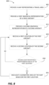
- FIG. 8 is a flowchart illustrating a method 800 for highlighting a geometric area of a user interface.
- the method 800 may be implemented on the system 100 of FIG. 1 , the system 200 of FIG. 2 , and/or a different system.
- the method 800 may be executed on one or more processors to generate a user interface according to embodiments described herein.
- the method 800 includes providing a map of a travel area (at block 805).
- the travel area may be the travel area of a first aircraft.
- the map may be configured to move based on a position of the first aircraft.
- the map may represent a fixed-size area around the first aircraft, and the map may change an area encompassed by the fixed-size area as the first aircraft moves through real space.
- the method further includes providing, on the map, a first graphical representation of the first aircraft (at block 810).
- the first graphical representation may represent a position of the first aircraft relative to the travel area, illustrated relative to the map.
- the method further includes providing, on the map, a second graphical representation of a second aircraft (at block 815).
- the second graphical representation may represent a position of the second aircraft relative to the travel area, illustrated relative to the map.
- the method 800 includes receiving a first location of the first aircraft.
- the system implementing the method 800 may receive the first location from a transceiver of the first aircraft, a control tower, a satellite, and/or some other source.
- the method 800 includes receiving a second location of the second aircraft.
- the system implementing the method 800 may receive the second location from a transceiver of the second aircraft, a control tower, a satellite, and/or some other source.
- the method 800 further includes determining whether the second location of the second aircraft is within a predetermined radius of the first location of the first aircraft (at block 830). This determination can be made by the electronic processor executing the method 800, a comparator, or by some other means.
- the method 800 includes highlighting a geometric area of the map based on the first location (at block 835). For example, the user interface may generate a darkened, semi-transparent circle around the first graphical representation, wherein the radius of the circle represents the first predetermined radius of the first aircraft. The highlighted area may allow quick identification of the first graphical representation and the second graphical representation by contrasting with the map. The geometric area may remain highlighted until the second aircraft is no longer within the predetermined radius of the first aircraft. The method 800 then returns to block 820. Returning to block 830, if the second aircraft is not within the predetermined radius of the first aircraft, the method 800 returns to block 820.
- the geometric area is not highlighted when the second aircraft is within the predetermined radius of the first aircraft and a special condition is met.
- the geometric area may not be highlighted when the first aircraft is within an area with an expected heightened amount of traffic, such as an airport.
- FIG. 9 is a flowchart illustrating a method 900 for indicating that a communication signal corresponding to a second aircraft has been lost.
- the method 900 may be implemented on the system 100 of FIG. 1 , the system 200 of FIG. 2 , and/or a different system.
- the method 900 may be executed on one or more processors to generate a user interface according to embodiments described herein.
- the method 900 includes providing a map of a travel area (at block 905).
- the travel area may be the travel area of a first aircraft.
- the map may be configured to move based on a position of the first aircraft.
- the method further includes providing, on the map, a first graphical representation of the first aircraft (at block 910).
- the first graphical representation may represent a position of the first aircraft relative to the travel area, illustrated relative to the map.
- the method further includes providing, on the map, a second graphical representation of the second aircraft (at block 915).
- the second graphical representation may represent a position of the second aircraft relative to the travel area, illustrated relative to the map.
- the method 900 includes receiving a first location of the first aircraft.
- the system implementing the method 900 may receive the first location from a transceiver of the first aircraft, a control tower, a satellite, and/or some other source.
- the method 900 includes receiving a second location of the second aircraft.
- the system implementing the method 900 may receive the second location from a transceiver of the second aircraft, a control tower, a satellite, and/or some other source.
- the method 900 further includes determining whether the communication signal indicating the position of the second aircraft is still being received (at block 930).
- the method 900 further includes transforming a property of the second graphical representation to indicate a time since the communication signal was lost. For example, an opacity of the second graphical representation may be decreased as a function of time since the communication signal was last received (at block 935). The method 900 then returns to block 920. Returning to block 930, if the second aircraft is not within the predetermined radius of the first aircraft, the method 900 returns to block 920.
- inventions described herein provide systems and methods for detecting traffic aircraft and displaying these traffic aircraft to an operator of an aircraft via an enhanced aircraft traffic interface.
- the enhanced aircraft traffic interface may allow for the operator of the aircraft to quickly and efficiently identify traffic aircraft within a vicinity of the aircraft, which enhances safe operations of the aircraft.
- the graphical user interfaces provided herein provide improved user interfaces to, among other things, EFB systems.
- the improved user interface provides pilots with important flight data and control capabilities though a single interface, resulting in less systems needing to be accessed. This reduces the user interactions required to access necessary data, improves pilot situational awareness, and provides more efficient operation of the aircraft because, among other things, aircraft traffic displays do not have to be manually adjusted based on aircraft entering into and leaving the vicinity of the ownship.
Landscapes
- Engineering & Computer Science (AREA)
- Physics & Mathematics (AREA)
- General Physics & Mathematics (AREA)
- Aviation & Aerospace Engineering (AREA)
- Radar, Positioning & Navigation (AREA)
- Remote Sensing (AREA)
- General Engineering & Computer Science (AREA)
- Theoretical Computer Science (AREA)
- Human Computer Interaction (AREA)
- Automation & Control Theory (AREA)
- Instructional Devices (AREA)
Applications Claiming Priority (1)
| Application Number | Priority Date | Filing Date | Title |
|---|---|---|---|
| US17/481,780 US12159545B2 (en) | 2021-09-22 | 2021-09-22 | Air traffic depiction for portable and installed aircraft displays |
Publications (2)
| Publication Number | Publication Date |
|---|---|
| EP4166906A2 true EP4166906A2 (de) | 2023-04-19 |
| EP4166906A3 EP4166906A3 (de) | 2023-06-21 |
Family
ID=83270959
Family Applications (1)
| Application Number | Title | Priority Date | Filing Date |
|---|---|---|---|
| EP22194511.6A Pending EP4166906A3 (de) | 2021-09-22 | 2022-09-08 | Luftverkehrsdarstellung für tragbare und installierte flugzeugdisplays |
Country Status (2)
| Country | Link |
|---|---|
| US (1) | US12159545B2 (de) |
| EP (1) | EP4166906A3 (de) |
Families Citing this family (1)
| Publication number | Priority date | Publication date | Assignee | Title |
|---|---|---|---|---|
| US12293056B2 (en) * | 2023-05-11 | 2025-05-06 | The Boeing Company | Fading PIREP icons based on validity of report |
Family Cites Families (16)
| Publication number | Priority date | Publication date | Assignee | Title |
|---|---|---|---|---|
| CA2197953C (en) * | 1997-02-19 | 2005-05-10 | Steve Janssen | User interface and method for maximizing the information presented on a screen |
| US8230355B1 (en) * | 2006-03-22 | 2012-07-24 | Adobe Systems Incorporated | Visual representation of a characteristic of an object in a space |
| US8195383B2 (en) * | 2006-11-29 | 2012-06-05 | The Boeing Company | System and method for electronic moving map and aeronautical context display |
| US8160755B2 (en) | 2008-09-30 | 2012-04-17 | Honeywell International Inc. | Displaying air traffic symbology based on relative importance |
| US8736465B2 (en) * | 2011-01-17 | 2014-05-27 | L-3 Communications Avionics Systems, Inc. | Aircraft traffic display |
| EP2584768B1 (de) * | 2011-10-21 | 2015-04-01 | LG Electronics Inc. | Mobiles Endgerät und Steuerverfahren dafür |
| KR101952219B1 (ko) * | 2012-04-04 | 2019-02-26 | 삼성전자 주식회사 | 아이콘 운용을 지원하는 단말기 및 이의 운용 방법 |
| US9405005B1 (en) * | 2012-04-24 | 2016-08-02 | The United States Of America As Represented By The Administrator Of The National Aeronautics And Space Administration | Automatic dependent surveillance broadcast (ADS-B) system for ownership and traffic situational awareness |
| US9478140B2 (en) | 2014-08-29 | 2016-10-25 | Honeywell International Inc. | System and method for displaying traffic and associated alerts on a three-dimensional airport moving map display |
| US9646504B2 (en) | 2015-10-08 | 2017-05-09 | The Boeing Company | Flight deck displays to enable visual separation standard |
| US10490089B2 (en) | 2017-07-12 | 2019-11-26 | Honeywell International Inc. | Cockpit display of traffic information (CDTI) assisted visual separation employing a vertical situation display |
| US11417227B2 (en) * | 2018-05-31 | 2022-08-16 | The Boeing Company | Aircraft detect and avoid gauge |
| US10867519B2 (en) | 2018-05-31 | 2020-12-15 | The Boeing Company | Aircraft flight information system and method |
| US10909865B2 (en) * | 2019-02-06 | 2021-02-02 | Honeywell International Inc. | System and method to identify, depict and alert distress and special traffic based on at least squawk codes |
| US20200320887A1 (en) * | 2019-04-02 | 2020-10-08 | Honeywell International Inc. | Systems and methods for probabilistically determining the intended flight route of an aircraft |
| DE102019117689B4 (de) * | 2019-07-01 | 2025-10-23 | Bayerische Motoren Werke Aktiengesellschaft | Verfahren und Steuereinheit zur Darstellung einer Verkehrssituation durch Ausblenden von Verkehrsteilnehmer-Symbolen |
-
2021
- 2021-09-22 US US17/481,780 patent/US12159545B2/en active Active
-
2022
- 2022-09-08 EP EP22194511.6A patent/EP4166906A3/de active Pending
Also Published As
| Publication number | Publication date |
|---|---|
| US12159545B2 (en) | 2024-12-03 |
| EP4166906A3 (de) | 2023-06-21 |
| US20230103832A1 (en) | 2023-04-06 |
Similar Documents
| Publication | Publication Date | Title |
|---|---|---|
| US7177731B2 (en) | Systems and methods for handling aircraft information received from an off-board source | |
| US10139474B2 (en) | Methods and systems for providing live weather data onboard an aircraft | |
| US9234982B2 (en) | Aircraft systems and methods for displaying weather information along a flight path | |
| EP3438614B1 (de) | Flugzeugsysteme und verfahren zur einstellung eines angezeigten sensorbildfeldes | |
| US9523580B2 (en) | System and method for aiding a pilot in locating an out of view landing site | |
| CN109491399B (zh) | 自动飞行控制系统和方法 | |
| US9501936B2 (en) | Aircraft systems and methods for displaying spacing information | |
| US9558674B2 (en) | Aircraft systems and methods to display enhanced runway lighting | |
| US9170126B2 (en) | Avionics navigation power range indicator | |
| US9340282B2 (en) | System and method for displaying vertical reference on a rotorcraft system | |
| US9168859B2 (en) | System and method for displaying visual flight reference points | |
| EP3767238A1 (de) | Verfahren und systeme zur visualisierung von motorneuzündung | |
| EP4166906A2 (de) | Luftverkehrsdarstellung für tragbare und installierte flugzeugdisplays | |
| US9563944B2 (en) | System and method for displaying optimized ownship position on a navigation display | |
| US9611051B2 (en) | Aircraft position display system | |
| EP3734573B1 (de) | Grafischer geschwindigkeitsleistungsmonitor mit flugintervallverwaltung | |
| US10748430B2 (en) | Systems and methods for selective terrain deemphasis | |
| US11769417B2 (en) | Methods and systems for representing flight mode annunciation information on a cockpit display | |
| US11598647B1 (en) | Marine traffic depiction for portable and installed aircraft displays | |
| US12572151B2 (en) | Selectable GPS altitude hold | |
| US12400549B2 (en) | Helideck flight path system for indication of obstacles present in a landing zone |
Legal Events
| Date | Code | Title | Description |
|---|---|---|---|
| PUAI | Public reference made under article 153(3) epc to a published international application that has entered the european phase |
Free format text: ORIGINAL CODE: 0009012 |
|
| STAA | Information on the status of an ep patent application or granted ep patent |
Free format text: STATUS: THE APPLICATION HAS BEEN PUBLISHED |
|
| AK | Designated contracting states |
Kind code of ref document: A2 Designated state(s): AL AT BE BG CH CY CZ DE DK EE ES FI FR GB GR HR HU IE IS IT LI LT LU LV MC MK MT NL NO PL PT RO RS SE SI SK SM TR |
|
| PUAL | Search report despatched |
Free format text: ORIGINAL CODE: 0009013 |
|
| AK | Designated contracting states |
Kind code of ref document: A3 Designated state(s): AL AT BE BG CH CY CZ DE DK EE ES FI FR GB GR HR HU IE IS IT LI LT LU LV MC MK MT NL NO PL PT RO RS SE SI SK SM TR |
|
| RIC1 | Information provided on ipc code assigned before grant |
Ipc: B64D 45/04 20060101ALI20230516BHEP Ipc: G08G 5/00 20060101ALI20230516BHEP Ipc: G01C 23/00 20060101ALI20230516BHEP Ipc: G01C 21/20 20060101AFI20230516BHEP |
|
| STAA | Information on the status of an ep patent application or granted ep patent |
Free format text: STATUS: REQUEST FOR EXAMINATION WAS MADE |
|
| 17P | Request for examination filed |
Effective date: 20231220 |
|
| RBV | Designated contracting states (corrected) |
Designated state(s): AL AT BE BG CH CY CZ DE DK EE ES FI FR GB GR HR HU IE IS IT LI LT LU LV MC MK MT NL NO PL PT RO RS SE SI SK SM TR |
|
| STAA | Information on the status of an ep patent application or granted ep patent |
Free format text: STATUS: EXAMINATION IS IN PROGRESS |
|
| 17Q | First examination report despatched |
Effective date: 20250219 |
|
| RIC1 | Information provided on ipc code assigned before grant |
Ipc: G01C 21/20 20060101AFI20260324BHEP Ipc: B64D 45/04 20060101ALI20260324BHEP Ipc: G08G 5/00 20060101ALI20260324BHEP Ipc: G01C 23/00 20060101ALI20260324BHEP Ipc: B64D 43/00 20060101ALI20260324BHEP Ipc: G08G 5/21 20250101ALI20260324BHEP Ipc: G08G 5/25 20250101ALI20260324BHEP Ipc: G08G 5/53 20250101ALI20260324BHEP Ipc: G08G 5/55 20250101ALI20260324BHEP Ipc: G08G 5/72 20250101ALI20260324BHEP |