EP4167360A1 - Batteriepack, fahrzeug und elektronische vorrichtung - Google Patents
Batteriepack, fahrzeug und elektronische vorrichtung Download PDFInfo
- Publication number
- EP4167360A1 EP4167360A1 EP21892378.7A EP21892378A EP4167360A1 EP 4167360 A1 EP4167360 A1 EP 4167360A1 EP 21892378 A EP21892378 A EP 21892378A EP 4167360 A1 EP4167360 A1 EP 4167360A1
- Authority
- EP
- European Patent Office
- Prior art keywords
- battery pack
- connection
- cell frame
- holes
- present disclosure
- Prior art date
- Legal status (The legal status is an assumption and is not a legal conclusion. Google has not performed a legal analysis and makes no representation as to the accuracy of the status listed.)
- Pending
Links
Images

Classifications
-
- H—ELECTRICITY
- H01—ELECTRIC ELEMENTS
- H01M—PROCESSES OR MEANS, e.g. BATTERIES, FOR THE DIRECT CONVERSION OF CHEMICAL ENERGY INTO ELECTRICAL ENERGY
- H01M50/00—Constructional details or processes of manufacture of the non-active parts of electrochemical cells other than fuel cells, e.g. hybrid cells
- H01M50/20—Mountings; Secondary casings or frames; Racks, modules or packs; Suspension devices; Shock absorbers; Transport or carrying devices; Holders
-
- H—ELECTRICITY
- H01—ELECTRIC ELEMENTS
- H01M—PROCESSES OR MEANS, e.g. BATTERIES, FOR THE DIRECT CONVERSION OF CHEMICAL ENERGY INTO ELECTRICAL ENERGY
- H01M10/00—Secondary cells; Manufacture thereof
- H01M10/42—Methods or arrangements for servicing or maintenance of secondary cells or secondary half-cells
- H01M10/425—Structural combination with electronic components, e.g. electronic circuits integrated to the outside of the casing
-
- H—ELECTRICITY
- H01—ELECTRIC ELEMENTS
- H01M—PROCESSES OR MEANS, e.g. BATTERIES, FOR THE DIRECT CONVERSION OF CHEMICAL ENERGY INTO ELECTRICAL ENERGY
- H01M10/00—Secondary cells; Manufacture thereof
- H01M10/42—Methods or arrangements for servicing or maintenance of secondary cells or secondary half-cells
- H01M10/48—Accumulators combined with arrangements for measuring, testing or indicating the condition of cells, e.g. the level or density of the electrolyte
- H01M10/482—Accumulators combined with arrangements for measuring, testing or indicating the condition of cells, e.g. the level or density of the electrolyte for several batteries or cells simultaneously or sequentially
-
- H—ELECTRICITY
- H01—ELECTRIC ELEMENTS
- H01M—PROCESSES OR MEANS, e.g. BATTERIES, FOR THE DIRECT CONVERSION OF CHEMICAL ENERGY INTO ELECTRICAL ENERGY
- H01M10/00—Secondary cells; Manufacture thereof
- H01M10/60—Heating or cooling; Temperature control
- H01M10/61—Types of temperature control
- H01M10/613—Cooling or keeping cold
-
- H—ELECTRICITY
- H01—ELECTRIC ELEMENTS
- H01M—PROCESSES OR MEANS, e.g. BATTERIES, FOR THE DIRECT CONVERSION OF CHEMICAL ENERGY INTO ELECTRICAL ENERGY
- H01M10/00—Secondary cells; Manufacture thereof
- H01M10/60—Heating or cooling; Temperature control
- H01M10/62—Heating or cooling; Temperature control specially adapted for specific applications
- H01M10/623—Portable devices, e.g. mobile telephones, cameras or pacemakers
-
- H—ELECTRICITY
- H01—ELECTRIC ELEMENTS
- H01M—PROCESSES OR MEANS, e.g. BATTERIES, FOR THE DIRECT CONVERSION OF CHEMICAL ENERGY INTO ELECTRICAL ENERGY
- H01M10/00—Secondary cells; Manufacture thereof
- H01M10/60—Heating or cooling; Temperature control
- H01M10/62—Heating or cooling; Temperature control specially adapted for specific applications
- H01M10/625—Vehicles
-
- H—ELECTRICITY
- H01—ELECTRIC ELEMENTS
- H01M—PROCESSES OR MEANS, e.g. BATTERIES, FOR THE DIRECT CONVERSION OF CHEMICAL ENERGY INTO ELECTRICAL ENERGY
- H01M10/00—Secondary cells; Manufacture thereof
- H01M10/60—Heating or cooling; Temperature control
- H01M10/65—Means for temperature control structurally associated with the cells
- H01M10/655—Solid structures for heat exchange or heat conduction
-
- H—ELECTRICITY
- H01—ELECTRIC ELEMENTS
- H01M—PROCESSES OR MEANS, e.g. BATTERIES, FOR THE DIRECT CONVERSION OF CHEMICAL ENERGY INTO ELECTRICAL ENERGY
- H01M10/00—Secondary cells; Manufacture thereof
- H01M10/60—Heating or cooling; Temperature control
- H01M10/65—Means for temperature control structurally associated with the cells
- H01M10/656—Means for temperature control structurally associated with the cells characterised by the type of heat-exchange fluid
- H01M10/6561—Gases
- H01M10/6562—Gases with free flow by convection only
-
- H—ELECTRICITY
- H01—ELECTRIC ELEMENTS
- H01M—PROCESSES OR MEANS, e.g. BATTERIES, FOR THE DIRECT CONVERSION OF CHEMICAL ENERGY INTO ELECTRICAL ENERGY
- H01M50/00—Constructional details or processes of manufacture of the non-active parts of electrochemical cells other than fuel cells, e.g. hybrid cells
- H01M50/20—Mountings; Secondary casings or frames; Racks, modules or packs; Suspension devices; Shock absorbers; Transport or carrying devices; Holders
- H01M50/204—Racks, modules or packs for multiple batteries or multiple cells
- H01M50/207—Racks, modules or packs for multiple batteries or multiple cells characterised by their shape
- H01M50/209—Racks, modules or packs for multiple batteries or multiple cells characterised by their shape adapted for prismatic or rectangular cells
-
- H—ELECTRICITY
- H01—ELECTRIC ELEMENTS
- H01M—PROCESSES OR MEANS, e.g. BATTERIES, FOR THE DIRECT CONVERSION OF CHEMICAL ENERGY INTO ELECTRICAL ENERGY
- H01M50/00—Constructional details or processes of manufacture of the non-active parts of electrochemical cells other than fuel cells, e.g. hybrid cells
- H01M50/20—Mountings; Secondary casings or frames; Racks, modules or packs; Suspension devices; Shock absorbers; Transport or carrying devices; Holders
- H01M50/204—Racks, modules or packs for multiple batteries or multiple cells
- H01M50/207—Racks, modules or packs for multiple batteries or multiple cells characterised by their shape
- H01M50/211—Racks, modules or packs for multiple batteries or multiple cells characterised by their shape adapted for pouch cells
-
- H—ELECTRICITY
- H01—ELECTRIC ELEMENTS
- H01M—PROCESSES OR MEANS, e.g. BATTERIES, FOR THE DIRECT CONVERSION OF CHEMICAL ENERGY INTO ELECTRICAL ENERGY
- H01M50/00—Constructional details or processes of manufacture of the non-active parts of electrochemical cells other than fuel cells, e.g. hybrid cells
- H01M50/20—Mountings; Secondary casings or frames; Racks, modules or packs; Suspension devices; Shock absorbers; Transport or carrying devices; Holders
- H01M50/204—Racks, modules or packs for multiple batteries or multiple cells
- H01M50/207—Racks, modules or packs for multiple batteries or multiple cells characterised by their shape
- H01M50/213—Racks, modules or packs for multiple batteries or multiple cells characterised by their shape adapted for cells having curved cross-section, e.g. round or elliptic
-
- H—ELECTRICITY
- H01—ELECTRIC ELEMENTS
- H01M—PROCESSES OR MEANS, e.g. BATTERIES, FOR THE DIRECT CONVERSION OF CHEMICAL ENERGY INTO ELECTRICAL ENERGY
- H01M50/00—Constructional details or processes of manufacture of the non-active parts of electrochemical cells other than fuel cells, e.g. hybrid cells
- H01M50/20—Mountings; Secondary casings or frames; Racks, modules or packs; Suspension devices; Shock absorbers; Transport or carrying devices; Holders
- H01M50/284—Mountings; Secondary casings or frames; Racks, modules or packs; Suspension devices; Shock absorbers; Transport or carrying devices; Holders with incorporated circuit boards, e.g. printed circuit boards [PCB]
-
- H—ELECTRICITY
- H01—ELECTRIC ELEMENTS
- H01M—PROCESSES OR MEANS, e.g. BATTERIES, FOR THE DIRECT CONVERSION OF CHEMICAL ENERGY INTO ELECTRICAL ENERGY
- H01M50/00—Constructional details or processes of manufacture of the non-active parts of electrochemical cells other than fuel cells, e.g. hybrid cells
- H01M50/20—Mountings; Secondary casings or frames; Racks, modules or packs; Suspension devices; Shock absorbers; Transport or carrying devices; Holders
- H01M50/296—Mountings; Secondary casings or frames; Racks, modules or packs; Suspension devices; Shock absorbers; Transport or carrying devices; Holders characterised by terminals of battery packs
-
- H—ELECTRICITY
- H01—ELECTRIC ELEMENTS
- H01M—PROCESSES OR MEANS, e.g. BATTERIES, FOR THE DIRECT CONVERSION OF CHEMICAL ENERGY INTO ELECTRICAL ENERGY
- H01M50/00—Constructional details or processes of manufacture of the non-active parts of electrochemical cells other than fuel cells, e.g. hybrid cells
- H01M50/50—Current conducting connections for cells or batteries
-
- H—ELECTRICITY
- H01—ELECTRIC ELEMENTS
- H01M—PROCESSES OR MEANS, e.g. BATTERIES, FOR THE DIRECT CONVERSION OF CHEMICAL ENERGY INTO ELECTRICAL ENERGY
- H01M10/00—Secondary cells; Manufacture thereof
- H01M10/42—Methods or arrangements for servicing or maintenance of secondary cells or secondary half-cells
- H01M10/425—Structural combination with electronic components, e.g. electronic circuits integrated to the outside of the casing
- H01M2010/4271—Battery management systems including electronic circuits, e.g. control of current or voltage to keep battery in healthy state, cell balancing
-
- H—ELECTRICITY
- H01—ELECTRIC ELEMENTS
- H01M—PROCESSES OR MEANS, e.g. BATTERIES, FOR THE DIRECT CONVERSION OF CHEMICAL ENERGY INTO ELECTRICAL ENERGY
- H01M2220/00—Batteries for particular applications
- H01M2220/20—Batteries in motive systems, e.g. vehicle, ship, plane
-
- H—ELECTRICITY
- H01—ELECTRIC ELEMENTS
- H01M—PROCESSES OR MEANS, e.g. BATTERIES, FOR THE DIRECT CONVERSION OF CHEMICAL ENERGY INTO ELECTRICAL ENERGY
- H01M2220/00—Batteries for particular applications
- H01M2220/30—Batteries in portable systems, e.g. mobile phone, laptop
-
- Y—GENERAL TAGGING OF NEW TECHNOLOGICAL DEVELOPMENTS; GENERAL TAGGING OF CROSS-SECTIONAL TECHNOLOGIES SPANNING OVER SEVERAL SECTIONS OF THE IPC; TECHNICAL SUBJECTS COVERED BY FORMER USPC CROSS-REFERENCE ART COLLECTIONS [XRACs] AND DIGESTS
- Y02—TECHNOLOGIES OR APPLICATIONS FOR MITIGATION OR ADAPTATION AGAINST CLIMATE CHANGE
- Y02E—REDUCTION OF GREENHOUSE GAS [GHG] EMISSIONS, RELATED TO ENERGY GENERATION, TRANSMISSION OR DISTRIBUTION
- Y02E60/00—Enabling technologies; Technologies with a potential or indirect contribution to GHG emissions mitigation
- Y02E60/10—Energy storage using batteries
Definitions
- the present disclosure relates to a battery pack, a vehicle, and an electronic device, and more particularly, to a battery pack in which maximum allowable current is increased by reducing electrical resistance, and an electronic device and a vehicle including the battery pack.
- lithium secondary batteries are in the spotlight because they have almost no memory effect compared to nickel-based secondary batteries, and thus have advantages of free charge/discharge, very low self-discharge rate, and high energy density.
- a lithium secondary battery mainly uses a lithium-based oxide and a carbon material as a positive electrode active material and a negative electrode active material, respectively.
- the lithium secondary battery includes an electrode assembly in which a positive electrode plate and a negative electrode plate to which the positive electrode active material and the negative electrode active material are respectively applied are located with a separator therebetween, and a casing, that is, a battery case, for sealing and accommodating the electrode assembly along with an electrolytic solution.
- a plurality of lithium secondary batteries may be provided in a battery pack.
- a battery pack is often mounted in a narrow space of a means of transportation, it is also necessary to minimize the size of a bus bar or a metal plate electrically connected to a plurality of secondary batteries.
- a battery pack of the related art has a large restriction on the shape or size of internal components, and thus, there is a great limit in increasing allowable current intensity for a bus bar or a metal plate.
- a battery pack applied to such a means of transportation has problems in that due to frequency vibration and impact, connection or coupling between internal components in the battery pack is released or the components are separated from one another. Accordingly, for the battery pack of the related art, a method of stably maintaining mounted states of internal components is required.
- the present disclosure is designed to solve the problems of the related art, and therefore the present disclosure is directed to providing a battery pack in which maximum allowable current is increased by reducing electrical resistance, and an electronic device and a vehicle including the battery pack.
- a battery pack including: a plurality of battery cells each provided with electrode terminals on both end portions thereof; at least two connection plates having electrical conductivity and configured to electrically connect the plurality of battery cells; and a cell frame having a plurality of hollow holes formed to surround at least a portion of each of the plurality of battery cells, allowing the connection plates to be mounted outside the cell frame, and including at least two first fixing protrusions protruding outward to respectively pass through at least two through-holes of the connection plates, wherein at least one of the at least two connection plates includes at least two through-holes spaced apart from one another in a current flowing direction.
- the battery pack may further include a battery management system (BMS) module configured to control charging and discharging of the plurality of battery cells, wherein each of the at least two connection plates includes: a connection terminal portion contacting the electrode terminal of each of the plurality of battery cells; and a connection extending portion extending from the connection terminal portion to be connected to the BMS module.
- BMS battery management system
- the cell frame may further include at least two second fixing protrusions protruding outward from an outer surface of the cell frame and configured to respectively support both end portions of the connection extending portion.
- the first fixing protrusion may obliquely extend outward.
- An outwardly protruding end portion of the first fixing protrusion may be bent at a certain angle.
- the cell frame may include a BMS mounting portion including: a seating rib protruding toward the BMS module to support a top surface or a bottom surface of the BMS module; and a plurality of fixing tabs protruding outward to support both side portions of the BMS module.
- the BMS module may include a protection circuit board including a printed circuit, wherein the protection circuit board includes a slit formed inward from an end portion, wherein a binding rib configured to be inserted into the slit is provided on the fixing tab.
- the cell frame may include: a ventilation hole formed by perforating a portion of the cell frame so that air flows between the plurality of battery cells; and a reinforcing rib extending to cross the inside of the ventilation hole.
- the at least two through-holes spaced apart from one another in the current flowing direction may be provided in the connection plate located at an end of current flow among the at least two connection plates.
- a pair of adjacent through-holes among the at least two through-holes may be spaced apart from one another in a direction perpendicular to the current flowing direction.
- a vehicle including at least one battery pack as described above.
- an electronic device including at least one battery pack as described above.
- connection plate in which at least two through-holes spaced apart from one another in a current flowing direction are formed is included, an increase in electrical resistance due to the formation of the at least two through-holes may be minimized. That is, because the connection plate has the through-hole spaced apart from one another in the current flowing direction, when compared to a case where at least two through-holes located on the same extension line are formed in a direction parallel to an X-axis, a cross-sectional area cut in a direction parallel to an X-Z plane in a region where the through-holes are formed is larger.
- an increase in electrical resistance of a connection plate due to a reduction in a cross-sectional area according to the formation of a plurality of through-holes may be minimized.
- the electrical resistance of a connection plate located at an end of current flow among a plurality of connection plates may be effectively reduced, thereby reducing a restriction on maximum allowable current and reducing the amount of heat generated by the electrical resistance.
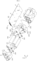
- FIG. 1 is a perspective view illustrating a battery pack according to an embodiment of the present disclosure.
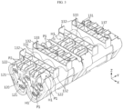
- FIG. 2 is an exploded perspective view illustrating the battery pack according to an embodiment of the present disclosure.
- FIG. 3 is a partial perspective view illustrating some elements of the battery pack according to an embodiment of the present disclosure.
- a battery pack 100 includes a plurality of battery cells 110, at least two connection plates 120, and a cell frame 130.
- the battery cell 110 may be a cylindrical battery cell 110.
- Electrode terminals 111 may be respectively located at the front (negative direction of a Y-axis) and the rear (positive direction of the Y-axis) of the battery cell 110.
- the electrode terminal 111 may be a positive electrode terminal or a negative electrode terminal.
- a Z-axis direction of FIG. 1 may refer to an up-down direction
- a Y-axis direction may refer to a front-back direction
- an X-axis direction may refer to a left-right direction.
- connection plates may be metal plates having electrical conductivity.
- the connection plate 120 may include a metal such as aluminum, copper, or nickel.
- the connection plate 120 may be configured to electrically connect the plurality of battery cells 110.
- the plurality of cylindrical battery cells 110 may be electrically connected in series or in parallel, or in series and in parallel, through the connection plate 120.
- An end portion of the connection plate 120 may be electrically connected to a positive electrode terminal 111 and/or a negative electrode terminal 112 of the cylindrical battery cell 110.
- the other end portion of the connection plate 120 may be electrically connected to a BMS module 140.
- each of the at least two connection plates 120 may include a connection terminal portion 121 and a connection extending portion 122.
- the connection terminal portion 121 may contact the electrode terminal of each of the plurality of battery cells 110.
- the connection terminal portion 121 may be welded to the electrode terminal to be electrically connected to the battery cell 110.
- the connection extending portion 122 may extend from the connection terminal portion 121 to be connected to the BMS module 140. An end portion of the connection extending portion 122 may be electrically connected to a connection terminal (not shown) of the BMS module 140.
- At least one of the at least two connection plates 120 may include at least two through-holes H1 spaced apart from one another in a current flowing direction.
- the at least two through-holes H1 spaced apart from one another in the current flowing direction (Y-axis direction) may be formed in the connection plate 120 located at an end of current flow, among the at least two connection plates 120.
- the at least two through-holes H1 spaced apart from one another in the current flowing direction may be provided in the connection extending portion 122.
- the current flowing direction may be a direction in which the connection plate 120 extends to be connected to the connection terminal of the BMS module 140.
- a pair of adjacent through-holes H1 among the at least two through-holes H1 may be spaced apart from one another in a direction (X-axis direction) substantially perpendicular to the current flowing direction. Due to the arrangement of the through-holes H1, when the connection plate 120 and a first fixing protrusion P1 described below are coupled to each other, the connection plate 120 may be more stably supported by the first fixing protrusion P1.
- the cell frame 130 may include a first frame 135 and a second frame 136.
- Each of the first frame 135 and the second frame 1365 may have a plurality of hollow holes O to surround at least a portion of each of the plurality of battery cells 110.
- the first frame 135 may have five hollow holes O to surround front portions of the five battery cells 110.
- the second frame 136 may have five hollow holes O to surround rear portions of the five battery cells 110.
- the cell frame 130 may have an electrically insulating material.
- the cell frame 130 may be formed of polyvinyl chloride (PVC).
- connection plate 120 may be mounted outside the cell frame 130.
- three connection plates 120 among six connection plates 120 may be mounted on a front end and an upper end of the first frame 135.
- the remaining three connection plates 120 may be mounted on a rear end and an upper end of the second frame 136.
- the cell frame 130 may include at least two first fixing protrusions P1.
- the at least two first fixing protrusions P1 may respectively pass through the at least two through-holes H1 of the connection plate 120.
- the first fixing protrusion P1 may protrude outward from an outer surface of the cell frame 130.
- the at least two first fixing protrusions P1 may be spaced apart from one another in the current flowing direction (Y direction) of the connection plate 120.
- the first fixing protrusion P1 may have a cylindrical shape extending upward or forward.
- the "current flowing direction" may be the same as, for example, a direction in which the connection plate 120 longitudinally extends toward the BMS module 140.
- the battery pack 100 may include two or more cell frames 130 arranged in the front-back direction.
- the battery pack 100 may further include an insulating sheet 150 having electrical insulation to be located between the two or more cell frames 130.
- the insulating sheet 150 may include, for example, a silicone material.
- connection plate 120 in which at least two through-holes H1 spaced apart from one another in the current flowing direction (Y-axis direction) are formed is included, an increase in electrical resistance due to the formation of the at least two through-holes H1 may be minimized.
- connection plate 120 when compared to a cross-sectional area of a portion where two through-holes are formed when two or more through-holes are not spaced apart from one another in the Y-axis direction, that is, are formed in parallel in the X direction in a connection plate of the prior art, a cross-sectional area of a portion where the through-holes H1 are formed in a direction perpendicular to current flow (e.g., cross-sectional area cut in the X-axis direction and the Z-axis direction when the Y-axis direction is the current flowing direction) is larger.
- connection plate 120 of the present disclosure includes the through-holes H1 spaced apart from one another in the Y-axis, when compared to a case where the two through-holes H1 are formed in parallel in the X-axis, a cross-sectional area cut in the X-axis direction and the Z-axis direction of a position where the through-holes H1 are formed is less reduced.
- connection plate 120 Accordingly, an increase in electrical resistance of the connection plate 120 according to the formation of the plurality of through-holes H1 may be minimized.
- the electrical resistance of the connection plate 120 located at an end of current flow among the plurality of connection plates 120 may be effectively reduced, thereby reducing a restriction on maximum allowable current and reducing the amount of heat generated by the electrical resistance.
- the battery pack 100 further includes the BMS module 140.
- BMS stands for battery management system. That is, the BMS module 140 may be configured to control charging and discharging of the plurality of battery cells 110.
- the BMS module 140 may include a protection circuit board 141 including a printed circuit.
- the cell frame 130 of the battery pack 100 may further include at least two second fixing protrusions P2.
- the second fixing protrusion P2 may protrude outward from an outer surface.
- the second fixing protrusion P2 may have a cylindrical shape extending upward or forward.
- the at least two second fixing protrusions P2 may respectively support both end portions of the connection extending portion 122 in the left-right direction.
- two second fixing protrusions P2 extending upward may be provided on the cell frame 130.
- the two second fixing protrusions P2 may be located to respectively support both end portions of the connection extending portion 122 of the connection plate 120 in the left-right direction toward the connection extending portion 122.
- connection extending portion 122 may be stably fixed to an outer surface of the cell frame 130. That is, a movement of the connection extending portion 122 in the left-right direction may be limited by the at least two second fixing protrusions P2. Accordingly, according to the present disclosure, an electrical connection state between the BMS module 140 and the connection extending portion 122 of the connection plate 120 may be stably maintained.
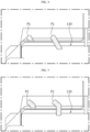
- FIG. 4 is a partial side view illustrating some elements of a battery pack according to another embodiment of the present disclosure.
- a shape of the first fixing protrusion P1 may be different from that of the first fixing protrusion P1 of FIG. 3 .
- Other elements may be the same as those of the battery pack of FIG. 3 .
- the first fixing protrusion P1 of FIG. 4 may obliquely extend outward.
- the first fixing protrusion P1 may be inclined forward. Accordingly, the first fixing protrusion P1 may be obliquely inserted into the through-hole H1 of the connection plate 120. Because the first fixing protrusion P1 obliquely extends, after the first fixing protrusion P1 is inserted into the through-hole H1 of the connection plate 120, the first fixing protrusion P1 may be prevented from being separated from the through-hole H1 due to external impact or an external force. That is, an inclined portion of the first fixing protrusion P1 may support a top surface of the connection plate 120 downward.
- the connection extending portion 122 may be stably fixed by the first fixing protrusions P1, electrical connection between an end portion of the connection extending portion 122 and a connection terminal (not shown) of the BMS module 140 may be stably maintained.
- FIG. 5 is a partial side view illustrating some elements of a battery pack according to still another embodiment of the present disclosure.
- a shape of the first fixing protrusion P1 may be different from that of the first fixing protrusion P1 of FIG. 3 .
- Other elements may be the same as those of the battery pack 100 of FIG. 3 .
- an outwardly protruding end portion of the first fixing protrusion P1 of FIG. 5 is bent at a certain angle, when compared to FIG. 3 .
- the protruding end portion of the first fixing protrusion P1 may be bent at about 30° with respect to a vertical direction.
- an upper end portion of the first fixing protrusion P1 may be inserted into the through-hole H1 formed in the connection extending portion 122 of the connection plate 120 at 30°, and then may be vertically inserted downward.
- connection extending portion 122 of the connection plate 120 may be effectively prevented from being separated from an outer surface of the cell frame 130. That is, an upward movement of the connection extending portion 122 may be limited by the bent shape of the first fixing protrusion P1. Accordingly, according to the present disclosure, because the connection extending portion 122 may be stably fixed by the first fixing protrusion P1, electrical connection between an end portion of the connection extending portion 122 and a connection terminal (not shown) of the BMS module 140 may be stably maintained.
- the cell frame 130 of the battery pack 100 may include a BMS mounting portion 137.
- the BMS mounting portion 137 may include a seating rib 131 and a plurality of fixing tabs 132.
- the seating rib 131 may support a top surface or a bottom surface of the BMS module 140.
- the seating rib 131 may have a rib shape protruding toward the BMS module 140. That is, the seating rib 131 may have a plate shape extending in the X-axis direction and a plate shape extending in the Y-axis direction.
- An upper end of the seating rib 131 may support upward a bottom surface of the protection circuit board 141 of the BMS module 140.
- the plurality of fixing tabs 132 may protrude outward to support both side portions of the BMS module 140.
- the plurality of fixing tabs 132 may be formed at a left end and a right end of the cell frame 130.
- the fixing tab 132 formed at the left end may support a left end of the BMS module 140 rightward.
- the fixing tab 132 formed at the right end may support a right end of the BMS module 140 leftward.
- the plurality of fixing tabs 132 may extend upward from a left end or a right end of the seating rib 131.
- the BMS mounting portion 137 including the seating rib 131 and the fixing tab 132 is provided, the BMS module 140 may be stably mounted on the battery pack 100. Accordingly, when the battery pack 100 is mounted in a means of transportation such as a vehicle, frequent vibration and impact may occur. However, because the battery pack 100 of the present disclosure is configured so that a movement of the BMS module 140 in the left-right direction and a downward movement are limited, a connection structure with the connection plate 120 may be effectively prevented from being disconnected due to shaking of the BMS module 140. Ultimately, according to the present disclosure, the durability of the battery pack 100 may be effectively increased.
- the protection circuit board 141 of the BMS module 140 may include a plurality of slits S formed inward from an end portion. Also, a binding rib 133 protruding toward the slit S may be provided on the fixing tab 132 to be inserted into the slit S.
- the binding rib 133 may longitudinally extend in the up-down direction. In this case, the binding rib 133 may be inserted into the slit S and may press an inner surface of the slit S inward, to fix the protection circuit board 141. That is, as the protection circuit board 141 moves downward, the binding rib 133 of the fixing tab 132 may be inserted into the slit S.
- the BMS module 140 may be fixed to the BMS mounting portion 137 when the binding rib 133 of the fixing tab 132 and the slit S of the protection circuit board 141 are coupled to each other. That is, when the BMS module 140 is mounted on the BMS mounting portion 137, due to a fastening structure between the slit S and the binding rib 133, a movement of the protection circuit board 141 in the front-back direction, the up-down direction, and the left-right direction may be limited.
- the BMS module 140 may be stably fixed to the cell frame 130 through the slit S of the protection circuit board 141 and the binding rib 133 formed on the fixing tab 132. Accordingly, according to the present disclosure, because the battery pack 100 is configured to limit a movement of the BMS module 140, a connection structure with the connection plate 120 may be effectively prevented from being disconnected due to shaking of the BMS module 140. Ultimately, according to the present disclosure, the durability of the battery pack 100 may be effectively increased.
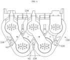
- FIG. 6 is a front view illustrating a battery pack according to an embodiment of the present disclosure.
- the cell frame 130 of the battery pack 100 may include a ventilation hole H2, and a reinforcing rib 134 formed in the ventilation hole H2.
- the ventilation hole H2 may be formed by perforating a portion so that air flows between the plurality of battery cells 110.
- the ventilation hole H2 may be formed by perforating a portion from a front end to a rear end of the cell frame 130.
- the ventilation hole H2 may be located between the plurality of battery cells 110. That is, the ventilation hole H2 may be configured to effectively move heat generated by the plurality of battery cells 110 in the front-back direction and discharge the heat to the outside.
- the reinforcing rib 134 may be configured to reinforce mechanical rigidity of the cell frame 130. That is, when a plurality of ventilation holes H2 are formed in the cell frame 130, mechanical rigidity of the cell frame 130 may be reduced. In order to compensate for the reduction, the reinforcing rib 134 may extend to cross the inside of the ventilation hole H2.
- the ventilation hole H2 is formed in the cell frame 130, the cooling efficiency of the battery pack 100 may be effectively improved. Also, according to the present disclosure, because the reinforcing rib 134 is provided on the cell frame 130, a decrease in mechanical rigidity due to the formation of the ventilation hole H2 in the cell frame 130 may be effectively reduced.
- a vehicle may include at least one battery pack 100 and a vehicle body having a receiving space in which the battery pack 100 is accommodated.
- a vehicle may be an electric vehicle, an electric kickboard, an electric scouter, an electric wheelchair, an electric bicycle, etc.
- An electronic device may include at least one battery pack 100 and an external housing having a receiving space in which the battery pack 100 is accommodated.
- Examples of the electronic device may include an interruptible power supply (UPS), a wireless computer, and a power storage device, etc.
- UPS interruptible power supply
Landscapes
- Chemical & Material Sciences (AREA)
- Chemical Kinetics & Catalysis (AREA)
- Electrochemistry (AREA)
- General Chemical & Material Sciences (AREA)
- Engineering & Computer Science (AREA)
- Manufacturing & Machinery (AREA)
- Microelectronics & Electronic Packaging (AREA)
- Life Sciences & Earth Sciences (AREA)
- Biophysics (AREA)
- Battery Mounting, Suspending (AREA)
- Connection Of Batteries Or Terminals (AREA)
- Secondary Cells (AREA)
Applications Claiming Priority (2)
| Application Number | Priority Date | Filing Date | Title |
|---|---|---|---|
| KR20200152313 | 2020-11-13 | ||
| PCT/KR2021/016578 WO2022103211A1 (ko) | 2020-11-13 | 2021-11-12 | 배터리 팩, 자동차, 및 전자 디바이스 |
Publications (2)
| Publication Number | Publication Date |
|---|---|
| EP4167360A1 true EP4167360A1 (de) | 2023-04-19 |
| EP4167360A4 EP4167360A4 (de) | 2024-09-25 |
Family
ID=81601608
Family Applications (1)
| Application Number | Title | Priority Date | Filing Date |
|---|---|---|---|
| EP21892378.7A Pending EP4167360A4 (de) | 2020-11-13 | 2021-11-12 | Batteriepack, fahrzeug und elektronische vorrichtung |
Country Status (6)
| Country | Link |
|---|---|
| US (1) | US20230369661A1 (de) |
| EP (1) | EP4167360A4 (de) |
| JP (1) | JP7513761B2 (de) |
| KR (1) | KR102861703B1 (de) |
| CN (1) | CN115917848A (de) |
| WO (1) | WO2022103211A1 (de) |
Families Citing this family (1)
| Publication number | Priority date | Publication date | Assignee | Title |
|---|---|---|---|---|
| DE102024209185A1 (de) * | 2024-09-24 | 2026-03-26 | Robert Bosch Gesellschaft mit beschränkter Haftung | Batterieanordnung für ein pedalgetriebenes Fahrzeug und pedalgetriebenes Fahrzeug mit Batterieanordnung |
Family Cites Families (19)
| Publication number | Priority date | Publication date | Assignee | Title |
|---|---|---|---|---|
| JP5201812B2 (ja) * | 2006-07-24 | 2013-06-05 | 三洋電機株式会社 | パック電池 |
| KR100886571B1 (ko) * | 2006-08-07 | 2009-03-05 | 주식회사 엘지화학 | 전지팩 케이스 |
| KR100934466B1 (ko) * | 2006-09-25 | 2009-12-30 | 주식회사 엘지화학 | 전지셀들의 전기적 연결을 위한 접속부재 |
| KR101036086B1 (ko) * | 2008-12-05 | 2011-05-19 | 삼성에스디아이 주식회사 | 이차전지 |
| JP5358251B2 (ja) * | 2009-03-31 | 2013-12-04 | 日立ビークルエナジー株式会社 | 蓄電モジュールおよび蓄電装置 |
| JP5663962B2 (ja) * | 2010-05-31 | 2015-02-04 | ソニー株式会社 | 電池ユニット |
| JP5722118B2 (ja) * | 2011-05-18 | 2015-05-20 | 日立オートモティブシステムズ株式会社 | 蓄電モジュールおよびその製造方法 |
| JP5823263B2 (ja) * | 2011-11-25 | 2015-11-25 | 三洋電機株式会社 | 電池パック |
| WO2013076911A1 (ja) * | 2011-11-25 | 2013-05-30 | パナソニック株式会社 | 電池パック |
| US9893342B2 (en) * | 2013-08-09 | 2018-02-13 | Hitachi Automotive Systems, Ltd. | Electricity storage module |
| JP6335864B2 (ja) * | 2015-11-20 | 2018-05-30 | 矢崎総業株式会社 | バスバー保持構造 |
| KR102210888B1 (ko) * | 2016-07-21 | 2021-02-02 | 삼성에스디아이 주식회사 | 배터리 팩 |
| KR102269112B1 (ko) * | 2017-04-24 | 2021-06-24 | 주식회사 엘지화학 | Bms 유동 방지용 댐핑부재 및 이를 포함하는 전지모듈 |
| KR102452406B1 (ko) * | 2018-03-26 | 2022-10-07 | 주식회사 엘지에너지솔루션 | 배터리 팩 |
| KR102243578B1 (ko) * | 2018-07-23 | 2021-04-21 | 주식회사 엘지화학 | 이차전지 팩 |
| KR102321513B1 (ko) * | 2018-08-21 | 2021-11-02 | 주식회사 엘지에너지솔루션 | 버스바 플레이트를 포함하는 배터리 모듈 |
| KR102301196B1 (ko) * | 2018-10-04 | 2021-09-09 | 주식회사 엘지에너지솔루션 | 접속 플레이트를 구비한 배터리 팩 |
| KR102326596B1 (ko) * | 2018-11-05 | 2021-11-12 | 주식회사 엘지에너지솔루션 | 탑재 구조물을 포함하는 배터리 팩 |
| CN209515831U (zh) * | 2019-02-15 | 2019-10-18 | 加百裕工业股份有限公司 | 电池装置及导电片体结构 |
-
2021
- 2021-11-12 JP JP2022573537A patent/JP7513761B2/ja active Active
- 2021-11-12 KR KR1020210155976A patent/KR102861703B1/ko active Active
- 2021-11-12 EP EP21892378.7A patent/EP4167360A4/de active Pending
- 2021-11-12 CN CN202180043317.1A patent/CN115917848A/zh active Pending
- 2021-11-12 WO PCT/KR2021/016578 patent/WO2022103211A1/ko not_active Ceased
- 2021-11-12 US US18/032,040 patent/US20230369661A1/en active Pending
Also Published As
| Publication number | Publication date |
|---|---|
| KR102861703B1 (ko) | 2025-09-18 |
| WO2022103211A1 (ko) | 2022-05-19 |
| US20230369661A1 (en) | 2023-11-16 |
| JP2023527470A (ja) | 2023-06-28 |
| JP7513761B2 (ja) | 2024-07-09 |
| EP4167360A4 (de) | 2024-09-25 |
| KR20220065717A (ko) | 2022-05-20 |
| CN115917848A (zh) | 2023-04-04 |
Similar Documents
| Publication | Publication Date | Title |
|---|---|---|
| EP4068480B1 (de) | Batteriepack, fahrzeug und elektronische vorrichtung, die dieselbe umfasst | |
| JP5259599B2 (ja) | バッテリーモジュールインタフェース | |
| JP7460777B2 (ja) | バッテリーモジュール、それを含むバッテリーパック及び自動車、並びにバッテリーパックを製造する方法 | |
| EP4053989B1 (de) | Batteriemodul mit stromschiene, batteriepack und fahrzeug | |
| KR102443098B1 (ko) | 모듈 하우징을 포함한 배터리 모듈 | |
| CN114245949B (zh) | 电池组、电子装置和车辆 | |
| KR102765183B1 (ko) | 모듈 버스바를 포함하는 배터리 모듈, 및 그것을 포함한 배터리 팩, 및 전자 디바이스 | |
| EP4199213A1 (de) | Batteriepack, energiespeichervorrichtung und fahrzeug | |
| JP7447318B2 (ja) | バッテリーモジュール、バッテリーパック及び自動車 | |
| CN115699409B (zh) | 电池组和车辆 | |
| EP4167360A1 (de) | Batteriepack, fahrzeug und elektronische vorrichtung | |
| CN114762178B (zh) | 电池模块、包括该电池模块的电池组以及汽车 | |
| EP4175036B1 (de) | Batteriemodul, batteriepack und energiespeichervorrichtung | |
| EP4187674B1 (de) | Batteriepack, elektronische vorrichtung, kraftfahrzeug und batterieverwaltungssystemmodul |
Legal Events
| Date | Code | Title | Description |
|---|---|---|---|
| STAA | Information on the status of an ep patent application or granted ep patent |
Free format text: STATUS: THE INTERNATIONAL PUBLICATION HAS BEEN MADE |
|
| PUAI | Public reference made under article 153(3) epc to a published international application that has entered the european phase |
Free format text: ORIGINAL CODE: 0009012 |
|
| STAA | Information on the status of an ep patent application or granted ep patent |
Free format text: STATUS: REQUEST FOR EXAMINATION WAS MADE |
|
| 17P | Request for examination filed |
Effective date: 20230112 |
|
| AK | Designated contracting states |
Kind code of ref document: A1 Designated state(s): AL AT BE BG CH CY CZ DE DK EE ES FI FR GB GR HR HU IE IS IT LI LT LU LV MC MK MT NL NO PL PT RO RS SE SI SK SM TR |
|
| DAV | Request for validation of the european patent (deleted) | ||
| DAX | Request for extension of the european patent (deleted) | ||
| A4 | Supplementary search report drawn up and despatched |
Effective date: 20240828 |
|
| RIC1 | Information provided on ipc code assigned before grant |
Ipc: H01M 10/48 20060101ALI20240822BHEP Ipc: H01M 50/50 20210101ALI20240822BHEP Ipc: H01M 50/296 20210101ALI20240822BHEP Ipc: H01M 50/284 20210101ALI20240822BHEP Ipc: H01M 50/211 20210101ALI20240822BHEP Ipc: H01M 50/209 20210101ALI20240822BHEP Ipc: H01M 10/613 20140101ALI20240822BHEP Ipc: H01M 10/623 20140101ALI20240822BHEP Ipc: H01M 10/625 20140101ALI20240822BHEP Ipc: H01M 10/6562 20140101ALI20240822BHEP Ipc: H01M 10/42 20060101ALI20240822BHEP Ipc: H01M 50/213 20210101ALI20240822BHEP Ipc: H01M 50/20 20210101AFI20240822BHEP |
|
| STAA | Information on the status of an ep patent application or granted ep patent |
Free format text: STATUS: EXAMINATION IS IN PROGRESS |
|
| 17Q | First examination report despatched |
Effective date: 20250509 |
|
| GRAP | Despatch of communication of intention to grant a patent |
Free format text: ORIGINAL CODE: EPIDOSNIGR1 |
|
| STAA | Information on the status of an ep patent application or granted ep patent |
Free format text: STATUS: GRANT OF PATENT IS INTENDED |
|
| INTG | Intention to grant announced |
Effective date: 20260102 |
|
| GRAS | Grant fee paid |
Free format text: ORIGINAL CODE: EPIDOSNIGR3 |
|
| GRAA | (expected) grant |
Free format text: ORIGINAL CODE: 0009210 |
|
| STAA | Information on the status of an ep patent application or granted ep patent |
Free format text: STATUS: THE PATENT HAS BEEN GRANTED |