EP4199213A1 - Batteriepack, energiespeichervorrichtung und fahrzeug - Google Patents
Batteriepack, energiespeichervorrichtung und fahrzeug Download PDFInfo
- Publication number
- EP4199213A1 EP4199213A1 EP22736866.9A EP22736866A EP4199213A1 EP 4199213 A1 EP4199213 A1 EP 4199213A1 EP 22736866 A EP22736866 A EP 22736866A EP 4199213 A1 EP4199213 A1 EP 4199213A1
- Authority
- EP
- European Patent Office
- Prior art keywords
- case
- flange portion
- sealing member
- battery pack
- battery
- Prior art date
- Legal status (The legal status is an assumption and is not a legal conclusion. Google has not performed a legal analysis and makes no representation as to the accuracy of the status listed.)
- Pending
Links
Images


Classifications
-
- H—ELECTRICITY
- H01—ELECTRIC ELEMENTS
- H01M—PROCESSES OR MEANS, e.g. BATTERIES, FOR THE DIRECT CONVERSION OF CHEMICAL ENERGY INTO ELECTRICAL ENERGY
- H01M50/00—Constructional details or processes of manufacture of the non-active parts of electrochemical cells other than fuel cells, e.g. hybrid cells
- H01M50/20—Mountings; Secondary casings or frames; Racks, modules or packs; Suspension devices; Shock absorbers; Transport or carrying devices; Holders
- H01M50/233—Mountings; Secondary casings or frames; Racks, modules or packs; Suspension devices; Shock absorbers; Transport or carrying devices; Holders characterised by physical properties of casings or racks, e.g. dimensions
- H01M50/24—Mountings; Secondary casings or frames; Racks, modules or packs; Suspension devices; Shock absorbers; Transport or carrying devices; Holders characterised by physical properties of casings or racks, e.g. dimensions adapted for protecting batteries from their environment, e.g. from corrosion
-
- H—ELECTRICITY
- H01—ELECTRIC ELEMENTS
- H01M—PROCESSES OR MEANS, e.g. BATTERIES, FOR THE DIRECT CONVERSION OF CHEMICAL ENERGY INTO ELECTRICAL ENERGY
- H01M50/00—Constructional details or processes of manufacture of the non-active parts of electrochemical cells other than fuel cells, e.g. hybrid cells
- H01M50/20—Mountings; Secondary casings or frames; Racks, modules or packs; Suspension devices; Shock absorbers; Transport or carrying devices; Holders
- H01M50/204—Racks, modules or packs for multiple batteries or multiple cells
-
- B—PERFORMING OPERATIONS; TRANSPORTING
- B60—VEHICLES IN GENERAL
- B60K—ARRANGEMENT OR MOUNTING OF PROPULSION UNITS OR OF TRANSMISSIONS IN VEHICLES; ARRANGEMENT OR MOUNTING OF PLURAL DIVERSE PRIME-MOVERS IN VEHICLES; AUXILIARY DRIVES FOR VEHICLES; INSTRUMENTATION OR DASHBOARDS FOR VEHICLES; ARRANGEMENTS IN CONNECTION WITH COOLING, AIR INTAKE, GAS EXHAUST OR FUEL SUPPLY OF PROPULSION UNITS IN VEHICLES
- B60K1/00—Arrangement or mounting of electrical propulsion units
- B60K1/04—Arrangement or mounting of electrical propulsion units of the electric storage means for propulsion
-
- B—PERFORMING OPERATIONS; TRANSPORTING
- B60—VEHICLES IN GENERAL
- B60L—PROPULSION OF ELECTRICALLY-PROPELLED VEHICLES; SUPPLYING ELECTRIC POWER FOR AUXILIARY EQUIPMENT OF ELECTRICALLY-PROPELLED VEHICLES; ELECTRODYNAMIC BRAKE SYSTEMS FOR VEHICLES IN GENERAL; MAGNETIC SUSPENSION OR LEVITATION FOR VEHICLES; MONITORING OPERATING VARIABLES OF ELECTRICALLY-PROPELLED VEHICLES; ELECTRIC SAFETY DEVICES FOR ELECTRICALLY-PROPELLED VEHICLES
- B60L50/00—Electric propulsion with power supplied within the vehicle
- B60L50/50—Electric propulsion with power supplied within the vehicle using propulsion power supplied by batteries or fuel cells
- B60L50/60—Electric propulsion with power supplied within the vehicle using propulsion power supplied by batteries or fuel cells using power supplied by batteries
- B60L50/64—Constructional details of batteries specially adapted for electric vehicles
-
- H—ELECTRICITY
- H01—ELECTRIC ELEMENTS
- H01M—PROCESSES OR MEANS, e.g. BATTERIES, FOR THE DIRECT CONVERSION OF CHEMICAL ENERGY INTO ELECTRICAL ENERGY
- H01M50/00—Constructional details or processes of manufacture of the non-active parts of electrochemical cells other than fuel cells, e.g. hybrid cells
- H01M50/20—Mountings; Secondary casings or frames; Racks, modules or packs; Suspension devices; Shock absorbers; Transport or carrying devices; Holders
- H01M50/202—Casings or frames around the primary casing of a single cell or a single battery
-
- H—ELECTRICITY
- H01—ELECTRIC ELEMENTS
- H01M—PROCESSES OR MEANS, e.g. BATTERIES, FOR THE DIRECT CONVERSION OF CHEMICAL ENERGY INTO ELECTRICAL ENERGY
- H01M50/00—Constructional details or processes of manufacture of the non-active parts of electrochemical cells other than fuel cells, e.g. hybrid cells
- H01M50/20—Mountings; Secondary casings or frames; Racks, modules or packs; Suspension devices; Shock absorbers; Transport or carrying devices; Holders
- H01M50/204—Racks, modules or packs for multiple batteries or multiple cells
- H01M50/207—Racks, modules or packs for multiple batteries or multiple cells characterised by their shape
- H01M50/209—Racks, modules or packs for multiple batteries or multiple cells characterised by their shape adapted for prismatic or rectangular cells
-
- H—ELECTRICITY
- H01—ELECTRIC ELEMENTS
- H01M—PROCESSES OR MEANS, e.g. BATTERIES, FOR THE DIRECT CONVERSION OF CHEMICAL ENERGY INTO ELECTRICAL ENERGY
- H01M50/00—Constructional details or processes of manufacture of the non-active parts of electrochemical cells other than fuel cells, e.g. hybrid cells
- H01M50/20—Mountings; Secondary casings or frames; Racks, modules or packs; Suspension devices; Shock absorbers; Transport or carrying devices; Holders
- H01M50/204—Racks, modules or packs for multiple batteries or multiple cells
- H01M50/207—Racks, modules or packs for multiple batteries or multiple cells characterised by their shape
- H01M50/211—Racks, modules or packs for multiple batteries or multiple cells characterised by their shape adapted for pouch cells
-
- H—ELECTRICITY
- H01—ELECTRIC ELEMENTS
- H01M—PROCESSES OR MEANS, e.g. BATTERIES, FOR THE DIRECT CONVERSION OF CHEMICAL ENERGY INTO ELECTRICAL ENERGY
- H01M50/00—Constructional details or processes of manufacture of the non-active parts of electrochemical cells other than fuel cells, e.g. hybrid cells
- H01M50/20—Mountings; Secondary casings or frames; Racks, modules or packs; Suspension devices; Shock absorbers; Transport or carrying devices; Holders
- H01M50/249—Mountings; Secondary casings or frames; Racks, modules or packs; Suspension devices; Shock absorbers; Transport or carrying devices; Holders specially adapted for aircraft or vehicles, e.g. cars or trains
-
- H—ELECTRICITY
- H01—ELECTRIC ELEMENTS
- H01M—PROCESSES OR MEANS, e.g. BATTERIES, FOR THE DIRECT CONVERSION OF CHEMICAL ENERGY INTO ELECTRICAL ENERGY
- H01M50/00—Constructional details or processes of manufacture of the non-active parts of electrochemical cells other than fuel cells, e.g. hybrid cells
- H01M50/20—Mountings; Secondary casings or frames; Racks, modules or packs; Suspension devices; Shock absorbers; Transport or carrying devices; Holders
- H01M50/251—Mountings; Secondary casings or frames; Racks, modules or packs; Suspension devices; Shock absorbers; Transport or carrying devices; Holders specially adapted for stationary devices, e.g. power plant buffering or backup power supplies
-
- H—ELECTRICITY
- H01—ELECTRIC ELEMENTS
- H01M—PROCESSES OR MEANS, e.g. BATTERIES, FOR THE DIRECT CONVERSION OF CHEMICAL ENERGY INTO ELECTRICAL ENERGY
- H01M50/00—Constructional details or processes of manufacture of the non-active parts of electrochemical cells other than fuel cells, e.g. hybrid cells
- H01M50/20—Mountings; Secondary casings or frames; Racks, modules or packs; Suspension devices; Shock absorbers; Transport or carrying devices; Holders
- H01M50/262—Mountings; Secondary casings or frames; Racks, modules or packs; Suspension devices; Shock absorbers; Transport or carrying devices; Holders with fastening means, e.g. locks
-
- H—ELECTRICITY
- H01—ELECTRIC ELEMENTS
- H01M—PROCESSES OR MEANS, e.g. BATTERIES, FOR THE DIRECT CONVERSION OF CHEMICAL ENERGY INTO ELECTRICAL ENERGY
- H01M50/00—Constructional details or processes of manufacture of the non-active parts of electrochemical cells other than fuel cells, e.g. hybrid cells
- H01M50/20—Mountings; Secondary casings or frames; Racks, modules or packs; Suspension devices; Shock absorbers; Transport or carrying devices; Holders
- H01M50/271—Lids or covers for the racks or secondary casings
-
- H—ELECTRICITY
- H01—ELECTRIC ELEMENTS
- H01M—PROCESSES OR MEANS, e.g. BATTERIES, FOR THE DIRECT CONVERSION OF CHEMICAL ENERGY INTO ELECTRICAL ENERGY
- H01M50/00—Constructional details or processes of manufacture of the non-active parts of electrochemical cells other than fuel cells, e.g. hybrid cells
- H01M50/30—Arrangements for facilitating escape of gases
- H01M50/383—Flame arresting or ignition-preventing means
-
- H—ELECTRICITY
- H01—ELECTRIC ELEMENTS
- H01M—PROCESSES OR MEANS, e.g. BATTERIES, FOR THE DIRECT CONVERSION OF CHEMICAL ENERGY INTO ELECTRICAL ENERGY
- H01M2200/00—Safety devices for primary or secondary batteries
-
- H—ELECTRICITY
- H01—ELECTRIC ELEMENTS
- H01M—PROCESSES OR MEANS, e.g. BATTERIES, FOR THE DIRECT CONVERSION OF CHEMICAL ENERGY INTO ELECTRICAL ENERGY
- H01M2200/00—Safety devices for primary or secondary batteries
- H01M2200/10—Temperature sensitive devices
-
- H—ELECTRICITY
- H01—ELECTRIC ELEMENTS
- H01M—PROCESSES OR MEANS, e.g. BATTERIES, FOR THE DIRECT CONVERSION OF CHEMICAL ENERGY INTO ELECTRICAL ENERGY
- H01M2220/00—Batteries for particular applications
- H01M2220/10—Batteries in stationary systems, e.g. emergency power source in plant
-
- H—ELECTRICITY
- H01—ELECTRIC ELEMENTS
- H01M—PROCESSES OR MEANS, e.g. BATTERIES, FOR THE DIRECT CONVERSION OF CHEMICAL ENERGY INTO ELECTRICAL ENERGY
- H01M2220/00—Batteries for particular applications
- H01M2220/20—Batteries in motive systems, e.g. vehicle, ship, plane
-
- Y—GENERAL TAGGING OF NEW TECHNOLOGICAL DEVELOPMENTS; GENERAL TAGGING OF CROSS-SECTIONAL TECHNOLOGIES SPANNING OVER SEVERAL SECTIONS OF THE IPC; TECHNICAL SUBJECTS COVERED BY FORMER USPC CROSS-REFERENCE ART COLLECTIONS [XRACs] AND DIGESTS
- Y02—TECHNOLOGIES OR APPLICATIONS FOR MITIGATION OR ADAPTATION AGAINST CLIMATE CHANGE
- Y02E—REDUCTION OF GREENHOUSE GAS [GHG] EMISSIONS, RELATED TO ENERGY GENERATION, TRANSMISSION OR DISTRIBUTION
- Y02E60/00—Enabling technologies; Technologies with a potential or indirect contribution to GHG emissions mitigation
- Y02E60/10—Energy storage using batteries
Definitions
- the present disclosure relates to a battery pack, an energy storage system, and a vehicle, and more specifically, to a battery pack with improved safety against fire or explosion.
- lithium secondary batteries are in the spotlight because they have almost no memory effect compared to nickel-based secondary batteries, and thus have advantages of free charge/discharge, very low self-discharge rate, and high energy density.
- a lithium secondary battery mainly uses a lithium-based oxide and a carbon material as a positive electrode active material and a negative electrode active material, respectively.
- the lithium secondary battery includes an electrode assembly in which a positive electrode plate and a negative electrode plate coated with the positive electrode active material and the negative electrode active material, respectively are disposed with a separator interposed therebetween, and a casing, that is, a battery case, for sealing and accommodating the electrode assembly along with an electrolyte.
- lithium secondary batteries may be classified into a can-type secondary battery in which an electrode assembly is embedded in a metal can, and a pouch-type secondary battery in which an electrode assembly is embedded in a pouch of an aluminum laminate sheet.
- Such a large-capacity battery module has a plurality of secondary batteries, and thus, when a fire or explosion occurs in the plurality of second batteries, flame and high-temperature gas are ejected, thereby causing damage such as the spread of fire to other battery packs in the vehicle, damage to other adjacent devices, or injury to occupants. Accordingly, there is a need for a method to improve the safety against fire or gas explosion of the battery pack.
- the present disclosure is designed to solve the problems of the related art, and therefore the present disclosure is directed to providing a battery pack with improved safety against fire or explosion.
- a battery pack including:
- the battery pack may further include a mounting member configured to mount the sealing member and having at least one open side so that the molten sealing member is discharged to the outside.
- a guide groove extending to guide a discharge direction of the molten sealing member may be formed in the mounting member.
- the battery pack may further include a guide member configured to receive the molten sealing member and form a moving path through which the received sealing member moves.
- the guide member may have an inclined surface extending downwardly in a direction between one end of the first case and the other end of the second case.
- a guide rib may be formed on the guide member to guide the sealing member to move from the receiving portion of the sealing member in a direction between one end of the first case and the other end of the second case.
- the first case includes a first accommodation portion accommodating one side of the battery module and having an open other side, and a first flange portion extending in a horizontally bent form from the other end of the first accommodation portion,
- the pack housing includes a gasket configured to be interposed between the first flange portion and the second flange portion, and a plurality of coupling members configured to couple the first flange portion and the second flange portion and spaced apart from each other by a predetermined distance, and the sealing member may be positioned between the plurality of coupling members.
- the sealing member may be interposed between the first flange portion and the second flange portion.
- an energy storage system including at least one battery pack.
- a vehicle including at least one battery pack.
- the present disclosure since the present disclosure includes a sealing member, it is possible to prevent high-temperature gas or flame from being discharged through a gap between one end of the first case and the other end of the second case when an internal battery module is ignited or exploded. That is, when the internal temperature of the pack housing increases over a predetermined temperature due to a fire, the sealing member may be melted and moved to cover the gap between one end of the first case and the other end of the second case. Accordingly, in the present disclosure, it is possible to prevent the flame ejected from the battery module from being discharged to the outside through the gap between one end of the first case and the other end of the second case. As a result, the battery pack of the present disclosure can improve safety against high-temperature gas or flame generated by an explosion or fire.
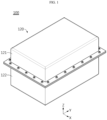
- FIG. 1 is a perspective view schematically showing a battery pack according to an embodiment of the present disclosure.
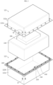
- FIG. 2 is an exploded perspective view schematically showing configurations of a battery pack according to an embodiment of the present disclosure.
- FIGS. 3 and 4 are partial vertical cross-sectional views schematically showing a portion of a battery pack according to an embodiment of the present disclosure.
- each of the arrows of the X-axis, Y-axis, and Z-axis shown in FIG. 1 may indicate a left direction, a rear direction, and an upward direction with respect to the battery pack.
- a battery pack 100 may include a battery module 110, a pack housing 120, and a sealing member 130.
- the battery module 110 may include a plurality of battery cells (not shown).
- the battery cell may be a pouch-type battery cell having an electrode assembly (not shown), an electrolyte (not shown), and a pouch accommodating them therein.
- the battery cell may include a positive electrode terminal and a negative electrode terminal.
- the battery pack 100 according to the present disclosure is not limited to the above-described pouch-type battery cells, and various types of battery cells known at the time of filing of this application may be employed.
- the battery module 110 may include at least one bus bar (not shown) configured to electrically interconnect the plurality of battery cells.
- the bus bar may include a conductive metal.
- the conductive metal may include, for example, copper, aluminum, nickel, or the like.
- the battery module 110 may include a module case configured to accommodate the plurality of battery cells therein.
- the module case may have a rectangular box shape of a rectangular parallelepiped.
- the module case may include an electrically insulating material.
- the electrically insulating material may be, for example, polyvinyl chloride.
- the battery module 110 may include external terminals (not shown).
- the external terminals may be an external positive electrode terminal and an external negative electrode terminal depending on the electrical polarity.
- Each of the external positive electrode terminal and the external negative electrode terminal may be electrically connected to a BMS module 190.
- the BMS module 190 may be configured to control charge/discharge of the battery module 110.
- the pack housing 120 may have an accommodation space in order to accommodate the battery module 110 therein.
- the pack housing 120 may include a first case 121 and a second case 122.
- the first case 121 may be configured to cover one side of the battery module 110.
- the first case 121 may have an upper wall to cover an upper portion of the battery module 110, and a front wall, a left wall, a rear wall, and a right wall to cover each of a front side, a left side, a rear side, and a right side of the battery module 110.
- the first case 121 may be configured such that the other side (lower portion) opposite to the one side is open. That is, the battery module 110 may be inserted through the open structure of the lower portion of the first case 121, so that the upper portion of the battery module 110 may be accommodated in the accommodation space of the first case 121.
- the second case 122 may be configured to cover the other side of the battery module 110.
- the second case 122 may include a lower wall to cover a lower portion of the battery module 110, and a front wall, a left wall, a rear wall, and a right wall to cover each of a front side, a left side, a rear side, and a right side of the battery module 110.
- the second case 122 may be configured such that one side (upper portion) opposite to the other side is open. That is, the battery module 110 may be inserted through the open structure of the upper portion of the second case 122, so that the lower portion of the battery module 110 may be accommodated in the accommodation space of the second case 122.
- One end of the second case 122 may be coupled to the other end of the first case 121.
- an upper end of the second case 122 may be coupled to a lower end of the first case 121.
- a coupling method may be bonding, welding, bolt (B) coupling, or the like.
- the sealing member 130 may be configured such that at least a portion thereof is melted at a predetermined temperature or higher.
- the predetermined temperature may be, for example, 327 degrees Celsius or higher, and preferably, the predetermined temperature may be 400 degrees Celsius to 600 degrees Celsius. More preferably, the predetermined temperature may be 550 degrees Celsius to 600 degrees Celsius.
- the sealing member 130 may include at least one of lead (Pb) having a melting point of about 327 degrees Celsius, zinc (Zn) having a melting point of about 420 degrees Celsius, and tellurium having a melting point of about 450 degrees Celsius. That is, when the internal temperature of the pack housing 120 reaches at least 600 degrees Celsius or higher, the sealing member 130 may include a material that can melt all portions.
- the sealing member 130 is not necessarily limited to these examples, and for example, any metal that can be melted in whole at 600 degrees Celsius may be applied.
- the sealing member 130 may be configured to be melted at a predetermined temperature or higher to flow into a gap between one end of the first case 121 and the other end of the second case 122. That is, the sealing member 130 may be configured to tightly seal a coupling portion between one end of the first case 121 and the other end of the second case 122. In other words, when melted at the predetermined temperature, the sealing member 130 may be configured such that the sealing member 130 in its liquid state flows into a gap between one end of the first case 121 and the other end of the second case 122 to fill the gap between one end of the first case 121 and the other end of the second case 122.
- the present disclosure since the present disclosure includes the sealing member 130, it is possible to prevent high-temperature gas or flame from being discharged through the gap between one end of the first case 121 and the other end of the second case 122, when the internal battery module 110 is ignited or exploded. That is, when the internal temperature of the pack housing 120 increases over, for example, 600 degrees Celsius due to a fire, the sealing member 130 may be melted and moved to cover the gap between one end of the first case 121 and the other end of the second case 122. Accordingly, in the present disclosure, it is possible to prevent the flame ejected from the battery module 110 from being discharged to the outside through the gap between one end of the first case 121 and the other end of the second case 122.
- the first case 121 may include a first accommodation portion 121a and a first flange portion 121b.
- the first accommodation portion 121a may accommodate one side of the battery module 110.
- the first accommodation portion 121a may have a shape in which the other side thereof is open.
- the first accommodation portion 121a may be configured to accommodate an upper portion of the battery module 110.
- the first accommodation portion 121a may have a shape in which a lower portion thereof is open.
- first flange portion 121b may be a portion of the first case 121 extending in a horizontally bent form from the other end of the first accommodation portion 121a.
- the first flange portion 121b may be a portion bent and extended in a horizontal direction from a lower end of the first accommodation portion 121a.
- the second case 122 may include a second accommodation portion 122a and a second flange portion 122b.
- the second accommodation portion 122a may accommodate the other side of the battery module 110.
- the second accommodation portion 122a may have a shape in which one side thereof is open.
- the second accommodation portion 122a may be configured to accommodate a lower portion of the battery module 110.
- the second accommodation portion 122a may have a shape in which an upper portion thereof is open.
- the second flange portion 122b may be a portion of the second case 122 extending in a horizontally bent form from one end of the second accommodation portion 122a.
- the second flange portion 122b may be a portion bent and extended in a horizontal direction from an upper end of the second accommodation portion 122a.
- the second flange portion 122b may be positioned to face a lower surface of the first flange portion 121b.
- the pack housing 120 may further include a gasket 160.
- the gasket 160 may be configured to be interposed between the first flange portion 121b and the second flange portion 122b.
- a plurality of protrusions configured to support a lower surface of the first flange portion 121b in an upward direction may be formed at an upper portion of the gasket 160.
- a plurality of protrusions configured to support an upper surface of the second flange portion 122b in a downward direction may be formed at a lower portion of the gasket 160.
- the gap between one end of the first case 121 and the other end of the second case 122 may be a gap between the first flange portion 121b and the second flange portion 122b.
- the gap may be formed between the lower surface of the first flange portion 121b and the upper surface of the gasket 160.
- the gap may be formed between the upper surface of the second flange portion 122b and the lower surface of the gasket 160.
- a gap may be formed between the gasket 160 and the first flange portion 121b or between the gasket 160 and the second flange portion 122b.
- first flange portion 121b and the second flange portion 122b may be coupled to each other.
- a plurality of coupling members configured to couple the first flange portion 121b and the second flange portion 122b and spaced apart from each other by a predetermined distance may be provided.
- the coupling member may include a bolt B and a nut N.
- a plurality of bolt holes T configured such that the bolt B is inserted, may be formed in each of the first flange portion 121b and the second flange portion 122b.
- the bolt B is inserted into the bolt hole T formed in each of the first flange portion 121b and the second flange portion 122b, and the bolt B may be fastened using the nut N so that the bolt B does not come out again from the bolt hole T.
- the sealing member 130 may be positioned between the plurality of coupling members. That is, a central position between the plurality of coupling members may be a portion where the coupling member has the least fastening force for pressing each of the first flange portion 121b and the second flange portion 122b. For this reason, the central position between the plurality of coupling members of the pack housing 120 may be a portion where flame is highly likely to be discharged in case of a fire or explosion of the battery module 110.
- the sealing member 130 is located between the plurality of coupling members in the present disclosure, it is possible to seal a portion where flame is highly likely to be discharged in case of a fire or explosion of the battery module 110, thereby effectively preventing the flame from being discharged to the outside of the pack housing 120.
- the sealing member 130 is not limited to being positioned only between the plurality of coupling members, and may be positioned at any portion of the pack housing 120 where a gap in circulation with the outside can occur.
- four sealing members 130 may be positioned at each of the four corner portions of the pack housing 120.
- a plurality of sealing members 130 may be positioned along the first flange portion 121b and the second flange portion 122b.
- the molten sealing member 130 may be configured to flow between the first flange portion 121b and the second flange portion 122b.
- the sealing member 130 in FIG. 3 is in a state of not being melted.
- the sealing member 130 may be melted to flow between the first flange portion 121b and the second flange portion 122b.
- the sealing member 130 introduced into the space between the first flange portion 121b and the second flange portion 122b may be hardened again due to a decrease in temperature.
- a temperature of the space between the first flange portion 121b and the second flange portion 122b which is located relatively outside the center of the pack housing 120 so that the influence of the outside air is large and the influence of the internal temperature increased due to the ignition is small, may be relatively low compared to the internal center of the pack housing 120.
- the present disclosure is configured such that the sealing member 130 is melted at a predetermined temperature or higher and then introduced between the first flange portion 121b and the second flange portion 122b, it is possible to prevent high-temperature gas or flame from being discharged through the gap between one end of the first case 121 and the other end of the second case 122, when the internal battery module 110 is ignited or exploded. That is, when the internal temperature of the pack housing 120 increases at, for example, 600 degrees Celsius or higher due to a fire, the sealing member 130 is melted and moved to cover the gap between one end of the first case 121 and the other end of the second case 122, and then hardened again to seal the gap more stably.
- FIG. 5 is a perspective view schematically showing a sealing member, a mounting member, and a guide member of a battery pack according to an embodiment of the present disclosure.
- the battery pack 100 may further include a mounting member 140.
- the mounting member 140 may be configured to mount the sealing member 130.
- the mounting member 140 includes an upper portion 141, a lower portion 142, and a connection portion 143 that connects each of the ends of the upper portion 141 and the lower portion 142 and extends in a vertical direction.
- a separated space S may be formed between the upper portion 141 and the lower portion 142.
- the sealing member 130 may be accommodated in the separated space S.
- the mounting member 140 may have a shape in which at least one side thereof is open so that the molten sealing member 130 is discharged to the outside.
- the mounting member 140 may have a shape opened toward the sidewall of the first case 121.
- the mounting member 140 may be partially spaced apart from the sidewall of the first case 121 to form a discharge space Y.
- the molten sealing member 130 may be moved downward through the discharge space Y.
- the mounting member 140 may include a coupling portion 144 configured to be partially coupled to an inner surface of the first accommodation portion 121a of the first case 121.
- the coupling portion 144 may be welded or bonded to the inner surface of the first accommodation portion 121a.
- the present disclosure includes the mounting member 140, so that the sealing member 130 can be stably accommodated, and thus, when the sealing member 130 is melted, the movement of the molten sealing member may be guided in a direction between one end of the first case 121 and the other end of the second case 122 through the discharge space.
- the battery pack 100 may further include a guide member 150.
- the guide member 150 may be configured to receive the molten sealing member 130.
- the guide member 150 may be configured to form a moving path through which the received sealing member 130 moves.
- the guide member 150 may have an inclined surface L extending downwardly in a direction between one end of the first case 121 and the other end of the second case 122.
- the guide member 150 may have an inclined surface L downward at an angle of 25 degrees.
- the guide member 150 may be positioned below the mounting member 140.
- the guide member 150 may be configured to receive the molten sealing member 130 passing through the discharge space between the mounting member 140 and the first accommodation portion 121a. That is, the inclined surface L of the guide member 150 may be positioned below the discharge space Y.
- the guide member 150 may include a fixing portion 151.
- the fixing portion 151 may be configured to be fixed to the inner surface of the second case 122.
- the fixing portion 151 may be welded or bonded to the inner surface of the second case 122.
- the present disclosure since the present disclosure includes the guide member 150, it is possible to stably receive the molten sealing member 130 discharged from the mounting member 140, and then guide the sealing member 130 to move in a direction between one end of the first case 121 and the other end of the second case 122. Accordingly, in the present disclosure, it is possible to prevent a malfunction in which the molten sealing member 130 is lost without being able to move in a direction between one end of the first case 121 and the other end of the second case 122, and thus the gap between one end of the first case 121 and the other end of the second case 122 may not be sealed.
- the guide member 150 may be configured to prevent flame from being introduced between one end of the first case 121 and the other end of the second case 122.
- a portion of the guide member 150 on which the inclined surface L is formed may be positioned between the first flange portion 121b and the second flange portion 122b. That is, the guide member 150 may screen the flame so that the flame is not directly transmitted to the gasket 160.
- the mounting member 140 is positioned between one end of the first case 121 and the other end of the second case 122, it is possible to screen the flame so that the flame is not directly transmitted to the gasket 160.
- the present disclosure since the present disclosure includes the guide member 150 positioned between the first flange portion 121b and the second flange portion 122b, it is possible to effectively prevent the flame from being introduced between one end of the first case 121 and the other end of the second case 122.
- FIG. 6 is a perspective view schematically showing a sealing member, a mounting member, and a guide member of a battery pack according to another embodiment of the present disclosure.
- the mounting member 140 of the battery pack 100 may further include a guide groove H when compared with the mounting member 140 in FIG. 5 .
- the other remaining configurations are the same as those of the battery pack 100 in FIG. 5 .
- a guide groove H extending to guide a discharge direction of the molten sealing member 130 may be formed in the mounting member 140 in FIG. 6 .
- the guide groove H may be formed such that the upper surface of the lower part 142 of the mounting member 140 is cut in a downward direction.
- the guide groove H may be formed such that the upper surface of the lower portion 142 of the mounting member 140 is grooved in a downward direction.
- the inner bottom surface of the guide groove H may have a downwardly inclined shape.
- the guide groove H may be configured such that the molten sealing member 130 may be stably accommodated on the inclined surface L of the guide member 150. That is, the guide groove H may guide the molten sealing member 130 to flow down to the inclined surface L of the guide member 150.
- the present disclosure since the present disclosure includes the mounting member 140 having the guide groove H, it is possible to guide the guide member 150 to stably receive the molten sealing member 130. Accordingly, in the present disclosure, it is possible to prevent a malfunction in which the molten sealing member 130 is lost without being able to move in a direction between the first flange portion 121b and the second flange portion 122b, and thus the gap between the first flange portion 121b and the second flange portion 122b may not be sealed.
- FIG. 7 is a perspective view schematically showing a sealing member, a mounting member, and a guide member of a battery pack according to still another embodiment of the present disclosure.
- the guide member 150 of the battery pack 100 may further include a guide rib P when compared with the guide member 150 in FIG. 5 .
- the other remaining configurations are the same as those of the battery pack 100 in FIG. 5 .
- the guide member 150 in FIG. 7 may include a guide rib P extending to guide a discharge direction of the molten sealing member 130.
- the guide rib P may be configured to allow the molten sealing member 130 to move in a direction between one end of the first case 121 and the other end of the second case 122 from the receiving portion of the sealing member 130. That is, the guide rib P may be formed at one or both ends of the inclined surface L in order to prevent the molten sealing member 130 from escaping to one side or both sides different from the direction without moving between the first flange portion 121b and the second flange portion 122b. Accordingly, the guide rib P may be configured such that the molten sealing member 130 may be stably moved without being separated from the inclined surface L of the guide member 150.
- the present disclosure since the present disclosure includes the guide member 150 having the guide rib P, it is possible to guide the molten sealing member 130 to stably move along the inclined surface L of the guide member 150. Ultimately, in the present disclosure, it is possible to prevent a malfunction in which the molten sealing member 130 is lost without being able to move in a direction between the first flange portion 121b and the second flange portion 122b, and thus the gap between the first flange portion 121b and the second flange portion 122b may not be sealed.
- FIG. 8 is a partial vertical cross-sectional view schematically showing a portion of a battery pack according to another embodiment of the present disclosure.
- the battery pack 100 may have a different position of the sealing member 130, unlike the battery pack 100 in FIG. 3 .
- the other remaining configurations are the same as those of the battery pack 100 in FIG. 3 .
- the sealing member 130 in FIG. 8 may be interposed between the first flange portion 121b and the second flange portion 122b.
- the sealing member 130 interposed between the first flange portion 121b and the second flange portion 122b may be configured to be melted at a predetermined temperature or higher to fill the gap between the first flange portion 121b and the second flange portion 122b.
- the sealing member 130 is melted at a predetermined temperature or higher, and then the molten sealing member 130 may be prevented from moving in the inner direction of the pack housing 120 by the guide member 150. That is, the guide member 150 may be configured such that a portion thereof supports the inner side of the sealing member 130 in an outward direction.
- the present disclosure since the present disclosure includes the sealing member 130 interposed between the first flange portion 121b and the second flange portion 122b, it is possible to effectively prevent the molten sealing member 130 from being lost to another place without being introduced between the first flange portion 121b and the second flange portion 122b. Accordingly, in the present disclosure, it is possible to prevent a malfunction in which the molten sealing member 130 is lost without being able to move in a direction between the first flange portion 121b and the second flange portion 122b, and thus the gap between the first flange portion 121b and the second flange portion 122b may not be sealed.
- the battery pack 100 may further include various devices (not shown) for controlling charge/ discharge of the battery module 110, for example, a BMS module (Battery Management System Module, 190 in FIG. 2 ), a current sensor, a fuse, and the like.
- the energy storage system (not shown) according to an embodiment of the present disclosure includes at least one of the above-described battery packs 100.
- the energy storage system may further include a rack case (not shown) having an accommodation space for accommodating the plurality of battery packs 100.
- the battery pack 100 according to an embodiment of the present disclosure may be included in a vehicle such as an electric vehicle or a hybrid vehicle. That is, the battery pack 100 according to the embodiment of the present disclosure described above may be mounted in the vehicle according to an embodiment of the present disclosure.
- the side cover 330 may be configured to be coupled to the vehicle body.
Landscapes
- Chemical & Material Sciences (AREA)
- Chemical Kinetics & Catalysis (AREA)
- Electrochemistry (AREA)
- General Chemical & Material Sciences (AREA)
- Engineering & Computer Science (AREA)
- Aviation & Aerospace Engineering (AREA)
- Mechanical Engineering (AREA)
- Transportation (AREA)
- Combustion & Propulsion (AREA)
- Life Sciences & Earth Sciences (AREA)
- Sustainable Development (AREA)
- Sustainable Energy (AREA)
- Power Engineering (AREA)
- Battery Mounting, Suspending (AREA)
Applications Claiming Priority (2)
| Application Number | Priority Date | Filing Date | Title |
|---|---|---|---|
| KR1020210002898A KR102824055B1 (ko) | 2021-01-08 | 2021-01-08 | 배터리 팩, 전력 저장 장치, 및 자동차 |
| PCT/KR2022/000254 WO2022149889A1 (ko) | 2021-01-08 | 2022-01-06 | 배터리 팩, 전력 저장 장치, 및 자동차 |
Publications (2)
| Publication Number | Publication Date |
|---|---|
| EP4199213A1 true EP4199213A1 (de) | 2023-06-21 |
| EP4199213A4 EP4199213A4 (de) | 2024-07-31 |
Family
ID=82358235
Family Applications (1)
| Application Number | Title | Priority Date | Filing Date |
|---|---|---|---|
| EP22736866.9A Pending EP4199213A4 (de) | 2021-01-08 | 2022-01-06 | Batteriepack, energiespeichervorrichtung und fahrzeug |
Country Status (6)
| Country | Link |
|---|---|
| US (1) | US20230307782A1 (de) |
| EP (1) | EP4199213A4 (de) |
| JP (1) | JP7549048B2 (de) |
| KR (1) | KR102824055B1 (de) |
| CN (1) | CN115803947A (de) |
| WO (1) | WO2022149889A1 (de) |
Families Citing this family (5)
| Publication number | Priority date | Publication date | Assignee | Title |
|---|---|---|---|---|
| WO2024029864A1 (ko) * | 2022-08-04 | 2024-02-08 | 주식회사 엘지에너지솔루션 | 배터리 팩 |
| KR102805821B1 (ko) * | 2022-09-29 | 2025-05-15 | 인지컨트롤스 주식회사 | 배터리 팩 및 이를 포함하는 자동차 |
| KR20240062612A (ko) | 2022-11-02 | 2024-05-09 | 주식회사 엘지에너지솔루션 | 배터리 팩 |
| KR102959160B1 (ko) | 2022-12-16 | 2026-04-29 | 주식회사 엘지에너지솔루션 | 보강부가 부가된 가스켓을 포함하는 전지팩 |
| KR20240145700A (ko) * | 2023-03-28 | 2024-10-07 | 주식회사 엘지에너지솔루션 | 열폭주시 화염 발생 지연을 위한 개스킷 및 이를 구비한 배터리 팩 |
Family Cites Families (19)
| Publication number | Priority date | Publication date | Assignee | Title |
|---|---|---|---|---|
| JP5151363B2 (ja) * | 2007-09-28 | 2013-02-27 | 三菱自動車工業株式会社 | 電気自動車用バッテリケース |
| US8277965B2 (en) * | 2009-04-22 | 2012-10-02 | Tesla Motors, Inc. | Battery pack enclosure with controlled thermal runaway release system |
| KR20110066448A (ko) * | 2009-12-11 | 2011-06-17 | 삼성에스디아이 주식회사 | 리튬 이차전지 |
| KR101312756B1 (ko) * | 2010-01-15 | 2013-09-27 | 미쯔비시 지도샤 고교 가부시끼가이샤 | 차량용 배터리 케이스 |
| JP2012209174A (ja) * | 2011-03-30 | 2012-10-25 | Panasonic Corp | 電池パック及び分離ケースの接合方法 |
| KR101698770B1 (ko) * | 2012-03-23 | 2017-01-23 | 삼성에스디아이 주식회사 | 배터리 팩 |
| JP2015153616A (ja) * | 2014-02-14 | 2015-08-24 | 株式会社オートネットワーク技術研究所 | バッテリパック |
| JP6217982B2 (ja) * | 2014-09-29 | 2017-10-25 | 豊田合成株式会社 | バスバー |
| KR102250898B1 (ko) * | 2016-05-27 | 2021-05-10 | 주식회사 엘지화학 | 전지용 파우치 외장재 및 이를 포함하는 전지 |
| DE102017205439B4 (de) * | 2017-03-30 | 2023-10-19 | Audi Ag | Gehäusevorrichtung und Kraftfahrzeug mit einer Gehäusevorrichtung |
| JP6996272B2 (ja) * | 2017-12-13 | 2022-01-17 | 日産自動車株式会社 | バッテリパック |
| CN109411640B (zh) * | 2018-09-26 | 2022-07-22 | 北京车和家信息技术有限公司 | 电池箱、电池包及车辆 |
| KR102182194B1 (ko) * | 2019-03-19 | 2020-11-24 | 주식회사 성우하이텍 | 전기자동차용 배터리 케이스의 조립 유닛 |
| US12580259B2 (en) * | 2019-03-27 | 2026-03-17 | Panasonic Energy Co., Ltd. | Battery pack |
| KR20210002898A (ko) | 2019-07-01 | 2021-01-11 | 삼성전자주식회사 | 외관 부재 및 그를 포함하는 전자 장치 |
| CN110459703B (zh) * | 2019-08-13 | 2024-05-31 | 广东微电新能源有限公司 | 一种电池装置以及电子设备 |
| CN110718655A (zh) * | 2019-10-17 | 2020-01-21 | 林进弟 | 一种电池阻燃性电动车 |
| KR102143111B1 (ko) * | 2019-12-31 | 2020-08-11 | 주식회사 한국항공조명 | 에너지 저장 시스템용 방폭 배터리 팩 |
| CN111755633B (zh) * | 2020-07-10 | 2022-04-05 | 瑞声科技(南京)有限公司 | 纽扣电池 |
-
2021
- 2021-01-08 KR KR1020210002898A patent/KR102824055B1/ko active Active
-
2022
- 2022-01-06 CN CN202280005421.6A patent/CN115803947A/zh active Pending
- 2022-01-06 EP EP22736866.9A patent/EP4199213A4/de active Pending
- 2022-01-06 WO PCT/KR2022/000254 patent/WO2022149889A1/ko not_active Ceased
- 2022-01-06 US US18/018,682 patent/US20230307782A1/en active Pending
- 2022-01-06 JP JP2022576516A patent/JP7549048B2/ja active Active
Also Published As
| Publication number | Publication date |
|---|---|
| KR102824055B1 (ko) | 2025-06-20 |
| JP2023529735A (ja) | 2023-07-11 |
| KR20220100465A (ko) | 2022-07-15 |
| CN115803947A (zh) | 2023-03-14 |
| EP4199213A4 (de) | 2024-07-31 |
| JP7549048B2 (ja) | 2024-09-10 |
| WO2022149889A1 (ko) | 2022-07-14 |
| US20230307782A1 (en) | 2023-09-28 |
Similar Documents
| Publication | Publication Date | Title |
|---|---|---|
| EP4068480B1 (de) | Batteriepack, fahrzeug und elektronische vorrichtung, die dieselbe umfasst | |
| US20230307782A1 (en) | Battery pack, energy storage system, and vehicle | |
| KR102832690B1 (ko) | 안전성이 향상된 배터리 모듈 | |
| US20230411784A1 (en) | Battery pack with improved safety | |
| KR102795087B1 (ko) | 배터리 모듈, 배터리 팩, 및 자동차 | |
| US20230261282A1 (en) | Battery pack, and automotive vehicle comprising same | |
| EP4087047B1 (de) | Batteriemodul, batteriepack damit und fahrzeug. | |
| EP4276997B1 (de) | Batteriemodul mit verbesserter sicherheit | |
| US12525681B2 (en) | Battery module, battery pack, and vehicle | |
| EP4187704A2 (de) | Batteriemodul, batteriepack und fahrzeug | |
| US20260088409A1 (en) | Battery pack, and electronic device and vehicle including the same | |
| US20240006711A1 (en) | Battery pack, electric wheelchair, and vehicle | |
| KR102779202B1 (ko) | 배터리 모듈, 배터리 팩 및 이를 포함하는 자동차 | |
| EP4167360A1 (de) | Batteriepack, fahrzeug und elektronische vorrichtung | |
| EP4661179A1 (de) | Batterieanordnung | |
| US20250266567A1 (en) | Battery pack | |
| KR20250049106A (ko) | 배터리 셀 |
Legal Events
| Date | Code | Title | Description |
|---|---|---|---|
| STAA | Information on the status of an ep patent application or granted ep patent |
Free format text: STATUS: THE INTERNATIONAL PUBLICATION HAS BEEN MADE |
|
| PUAI | Public reference made under article 153(3) epc to a published international application that has entered the european phase |
Free format text: ORIGINAL CODE: 0009012 |
|
| STAA | Information on the status of an ep patent application or granted ep patent |
Free format text: STATUS: REQUEST FOR EXAMINATION WAS MADE |
|
| 17P | Request for examination filed |
Effective date: 20230315 |
|
| AK | Designated contracting states |
Kind code of ref document: A1 Designated state(s): AL AT BE BG CH CY CZ DE DK EE ES FI FR GB GR HR HU IE IS IT LI LT LU LV MC MK MT NL NO PL PT RO RS SE SI SK SM TR |
|
| DAV | Request for validation of the european patent (deleted) | ||
| DAX | Request for extension of the european patent (deleted) | ||
| A4 | Supplementary search report drawn up and despatched |
Effective date: 20240701 |
|
| RIC1 | Information provided on ipc code assigned before grant |
Ipc: H01M 50/383 20210101ALI20240625BHEP Ipc: H01M 50/271 20210101ALI20240625BHEP Ipc: H01M 50/262 20210101ALI20240625BHEP Ipc: H01M 50/211 20210101ALI20240625BHEP Ipc: H01M 50/209 20210101ALI20240625BHEP Ipc: H01M 50/204 20210101ALI20240625BHEP Ipc: B60L 50/64 20190101ALI20240625BHEP Ipc: H01M 50/202 20210101ALI20240625BHEP Ipc: B60K 1/04 20190101ALI20240625BHEP Ipc: H01M 50/251 20210101ALI20240625BHEP Ipc: H01M 50/249 20210101ALI20240625BHEP Ipc: H01M 50/24 20210101AFI20240625BHEP |
|
| STAA | Information on the status of an ep patent application or granted ep patent |
Free format text: STATUS: EXAMINATION IS IN PROGRESS |
|
| 17Q | First examination report despatched |
Effective date: 20251007 |