EP4167429A1 - Dispositif de stockage d'énergie, système de stockage d'énergie le comprenant et procédé de commande, circuit de précharge pour dispositif de stockage d'énergie - Google Patents
Dispositif de stockage d'énergie, système de stockage d'énergie le comprenant et procédé de commande, circuit de précharge pour dispositif de stockage d'énergie Download PDFInfo
- Publication number
- EP4167429A1 EP4167429A1 EP22201996.0A EP22201996A EP4167429A1 EP 4167429 A1 EP4167429 A1 EP 4167429A1 EP 22201996 A EP22201996 A EP 22201996A EP 4167429 A1 EP4167429 A1 EP 4167429A1
- Authority
- EP
- European Patent Office
- Prior art keywords
- node
- current
- energy storage
- switching unit
- unit
- Prior art date
- Legal status (The legal status is an assumption and is not a legal conclusion. Google has not performed a legal analysis and makes no representation as to the accuracy of the status listed.)
- Pending
Links
Images





Classifications
-
- H—ELECTRICITY
- H02—GENERATION; CONVERSION OR DISTRIBUTION OF ELECTRIC POWER
- H02J—ELECTRIC POWER NETWORKS; CIRCUIT ARRANGEMENTS OR SYSTEMS FOR SUPPLYING OR DISTRIBUTING ELECTRIC POWER; SYSTEMS FOR STORING ELECTRIC ENERGY
- H02J7/00—Circuit arrangements for charging or discharging batteries or for supplying loads from batteries
- H02J7/60—Circuit arrangements for charging or discharging batteries or for supplying loads from batteries including safety or protection arrangements
- H02J7/62—Circuit arrangements for charging or discharging batteries or for supplying loads from batteries including safety or protection arrangements against overcurrent
-
- H—ELECTRICITY
- H02—GENERATION; CONVERSION OR DISTRIBUTION OF ELECTRIC POWER
- H02J—ELECTRIC POWER NETWORKS; CIRCUIT ARRANGEMENTS OR SYSTEMS FOR SUPPLYING OR DISTRIBUTING ELECTRIC POWER; SYSTEMS FOR STORING ELECTRIC ENERGY
- H02J7/00—Circuit arrangements for charging or discharging batteries or for supplying loads from batteries
- H02J7/90—Regulation of charging or discharging current or voltage
-
- B—PERFORMING OPERATIONS; TRANSPORTING
- B60—VEHICLES IN GENERAL
- B60L—PROPULSION OF ELECTRICALLY-PROPELLED VEHICLES; SUPPLYING ELECTRIC POWER FOR AUXILIARY EQUIPMENT OF ELECTRICALLY-PROPELLED VEHICLES; ELECTRODYNAMIC BRAKE SYSTEMS FOR VEHICLES IN GENERAL; MAGNETIC SUSPENSION OR LEVITATION FOR VEHICLES; MONITORING OPERATING VARIABLES OF ELECTRICALLY-PROPELLED VEHICLES; ELECTRIC SAFETY DEVICES FOR ELECTRICALLY-PROPELLED VEHICLES
- B60L58/00—Methods or circuit arrangements for monitoring or controlling batteries or fuel cells, specially adapted for electric vehicles
- B60L58/10—Methods or circuit arrangements for monitoring or controlling batteries or fuel cells, specially adapted for electric vehicles for monitoring or controlling batteries
- B60L58/18—Methods or circuit arrangements for monitoring or controlling batteries or fuel cells, specially adapted for electric vehicles for monitoring or controlling batteries of two or more battery modules
-
- H—ELECTRICITY
- H01—ELECTRIC ELEMENTS
- H01M—PROCESSES OR MEANS, e.g. BATTERIES, FOR THE DIRECT CONVERSION OF CHEMICAL ENERGY INTO ELECTRICAL ENERGY
- H01M10/00—Secondary cells; Manufacture thereof
- H01M10/42—Methods or arrangements for servicing or maintenance of secondary cells or secondary half-cells
- H01M10/425—Structural combination with electronic components, e.g. electronic circuits integrated to the outside of the casing
-
- H—ELECTRICITY
- H01—ELECTRIC ELEMENTS
- H01M—PROCESSES OR MEANS, e.g. BATTERIES, FOR THE DIRECT CONVERSION OF CHEMICAL ENERGY INTO ELECTRICAL ENERGY
- H01M10/00—Secondary cells; Manufacture thereof
- H01M10/42—Methods or arrangements for servicing or maintenance of secondary cells or secondary half-cells
- H01M10/44—Methods for charging or discharging
- H01M10/441—Methods for charging or discharging for several batteries or cells simultaneously or sequentially
-
- H—ELECTRICITY
- H01—ELECTRIC ELEMENTS
- H01M—PROCESSES OR MEANS, e.g. BATTERIES, FOR THE DIRECT CONVERSION OF CHEMICAL ENERGY INTO ELECTRICAL ENERGY
- H01M50/00—Constructional details or processes of manufacture of the non-active parts of electrochemical cells other than fuel cells, e.g. hybrid cells
- H01M50/20—Mountings; Secondary casings or frames; Racks, modules or packs; Suspension devices; Shock absorbers; Transport or carrying devices; Holders
- H01M50/204—Racks, modules or packs for multiple batteries or multiple cells
-
- H—ELECTRICITY
- H01—ELECTRIC ELEMENTS
- H01M—PROCESSES OR MEANS, e.g. BATTERIES, FOR THE DIRECT CONVERSION OF CHEMICAL ENERGY INTO ELECTRICAL ENERGY
- H01M50/00—Constructional details or processes of manufacture of the non-active parts of electrochemical cells other than fuel cells, e.g. hybrid cells
- H01M50/20—Mountings; Secondary casings or frames; Racks, modules or packs; Suspension devices; Shock absorbers; Transport or carrying devices; Holders
- H01M50/296—Mountings; Secondary casings or frames; Racks, modules or packs; Suspension devices; Shock absorbers; Transport or carrying devices; Holders characterised by terminals of battery packs
-
- H—ELECTRICITY
- H01—ELECTRIC ELEMENTS
- H01M—PROCESSES OR MEANS, e.g. BATTERIES, FOR THE DIRECT CONVERSION OF CHEMICAL ENERGY INTO ELECTRICAL ENERGY
- H01M50/00—Constructional details or processes of manufacture of the non-active parts of electrochemical cells other than fuel cells, e.g. hybrid cells
- H01M50/50—Current conducting connections for cells or batteries
- H01M50/502—Interconnectors for connecting terminals of adjacent batteries; Interconnectors for connecting cells outside a battery casing
- H01M50/509—Interconnectors for connecting terminals of adjacent batteries; Interconnectors for connecting cells outside a battery casing characterised by the type of connection, e.g. mixed connections
- H01M50/512—Connection only in parallel
-
- H—ELECTRICITY
- H02—GENERATION; CONVERSION OR DISTRIBUTION OF ELECTRIC POWER
- H02J—ELECTRIC POWER NETWORKS; CIRCUIT ARRANGEMENTS OR SYSTEMS FOR SUPPLYING OR DISTRIBUTING ELECTRIC POWER; SYSTEMS FOR STORING ELECTRIC ENERGY
- H02J7/00—Circuit arrangements for charging or discharging batteries or for supplying loads from batteries
- H02J7/50—Circuit arrangements for charging or discharging batteries or for supplying loads from batteries acting upon multiple batteries simultaneously or sequentially
-
- H—ELECTRICITY
- H02—GENERATION; CONVERSION OR DISTRIBUTION OF ELECTRIC POWER
- H02J—ELECTRIC POWER NETWORKS; CIRCUIT ARRANGEMENTS OR SYSTEMS FOR SUPPLYING OR DISTRIBUTING ELECTRIC POWER; SYSTEMS FOR STORING ELECTRIC ENERGY
- H02J7/00—Circuit arrangements for charging or discharging batteries or for supplying loads from batteries
- H02J7/60—Circuit arrangements for charging or discharging batteries or for supplying loads from batteries including safety or protection arrangements
- H02J7/663—Circuit arrangements for charging or discharging batteries or for supplying loads from batteries including safety or protection arrangements using battery or load disconnect circuits
-
- B—PERFORMING OPERATIONS; TRANSPORTING
- B60—VEHICLES IN GENERAL
- B60L—PROPULSION OF ELECTRICALLY-PROPELLED VEHICLES; SUPPLYING ELECTRIC POWER FOR AUXILIARY EQUIPMENT OF ELECTRICALLY-PROPELLED VEHICLES; ELECTRODYNAMIC BRAKE SYSTEMS FOR VEHICLES IN GENERAL; MAGNETIC SUSPENSION OR LEVITATION FOR VEHICLES; MONITORING OPERATING VARIABLES OF ELECTRICALLY-PROPELLED VEHICLES; ELECTRIC SAFETY DEVICES FOR ELECTRICALLY-PROPELLED VEHICLES
- B60L2200/00—Type of vehicles
- B60L2200/32—Waterborne vessels
-
- B—PERFORMING OPERATIONS; TRANSPORTING
- B60—VEHICLES IN GENERAL
- B60L—PROPULSION OF ELECTRICALLY-PROPELLED VEHICLES; SUPPLYING ELECTRIC POWER FOR AUXILIARY EQUIPMENT OF ELECTRICALLY-PROPELLED VEHICLES; ELECTRODYNAMIC BRAKE SYSTEMS FOR VEHICLES IN GENERAL; MAGNETIC SUSPENSION OR LEVITATION FOR VEHICLES; MONITORING OPERATING VARIABLES OF ELECTRICALLY-PROPELLED VEHICLES; ELECTRIC SAFETY DEVICES FOR ELECTRICALLY-PROPELLED VEHICLES
- B60L58/00—Methods or circuit arrangements for monitoring or controlling batteries or fuel cells, specially adapted for electric vehicles
- B60L58/10—Methods or circuit arrangements for monitoring or controlling batteries or fuel cells, specially adapted for electric vehicles for monitoring or controlling batteries
- B60L58/12—Methods or circuit arrangements for monitoring or controlling batteries or fuel cells, specially adapted for electric vehicles for monitoring or controlling batteries responding to state of charge [SoC]
-
- H—ELECTRICITY
- H01—ELECTRIC ELEMENTS
- H01M—PROCESSES OR MEANS, e.g. BATTERIES, FOR THE DIRECT CONVERSION OF CHEMICAL ENERGY INTO ELECTRICAL ENERGY
- H01M2220/00—Batteries for particular applications
- H01M2220/20—Batteries in motive systems, e.g. vehicle, ship, plane
-
- H—ELECTRICITY
- H02—GENERATION; CONVERSION OR DISTRIBUTION OF ELECTRIC POWER
- H02J—ELECTRIC POWER NETWORKS; CIRCUIT ARRANGEMENTS OR SYSTEMS FOR SUPPLYING OR DISTRIBUTING ELECTRIC POWER; SYSTEMS FOR STORING ELECTRIC ENERGY
- H02J2105/00—Networks for supplying or distributing electric power characterised by their spatial reach or by the load
- H02J2105/30—Networks for supplying or distributing electric power characterised by their spatial reach or by the load the load networks being external to vehicles, i.e. exchanging power with vehicles
- H02J2105/31—Networks for supplying or distributing electric power characterised by their spatial reach or by the load the load networks being external to vehicles, i.e. exchanging power with vehicles for ships or vessels
Definitions
- the present disclosure relates to an energy storage device, in particular an electrical energy storage device, for a watercraft and an energy storage system for a watercraft with at least two such energy storage devices which are connected to one another in parallel.
- the disclosure further relates to control methods for the energy storage device and for the energy storage system and a pre-charge circuit for an energy storage device.
- Electrical energy storage devices such as batteries
- the load can be, for example, a propulsion electric motor of a watercraft such as a boat, a ship or a ferry.
- Batteries, in particular lithium-ion-based batteries usually have an integrated main switch for safety reasons, which can at least interrupt the current flowing out of the battery, in particular a discharge current.
- batteries can also be connected to one another initially or to switch on a battery bank which has a plurality of batteries, in order to form a switched-on battery bank.
- a battery When a battery is connected to a load that has a voltage source property, such as a capacitor, if the voltage levels of the battery and load are different, a large transient current flows when the main switch is closed, which can damage the main switch and other circuit components of the battery. It is therefore desirable to match or adapt the voltage levels of the battery and load prior to closing the main switch.
- a pre-charging circuit is usually used for this.
- Simple pre-charge circuits only include or consist of a switched resistor.
- the pre-charge current varies greatly as a function of the voltage at the terminals of the battery or the load voltage. It may increase depending on the capacity of the load very large power loss pulses in the resistor, which is why the design of the resistor for varying capacitance values is problematic. If the load has not only capacitive but also resistive components, it is often not possible to reach a voltage level at the load at which the main switch can be closed without problems due to the voltage division between the resistance of the pre-charging circuit and that of the load during pre-charging.
- External charging devices also called chargers, for batteries of this type typically have a so-called CCCV (“Constant Current, Constant Voltage”) charging characteristic or carry out a CCCV charging method.
- CCCV Constant Current, Constant Voltage
- a constant current phase charging takes place at a constant charging current that is limited by the external charging device.
- a constant voltage phase in which charging takes place at a constant voltage provided by the external charging device.
- the transition from the constant current phase to the constant voltage phase takes place when the battery voltage reaches a specified end-of-charge voltage.
- the battery voltage is monitored by the external charger.
- the charging current drops slowly and charging is terminated when the charging current has fallen below a threshold value.
- the external charging device is typically equipped with a negative tolerance.
- the external charging device already switches to the constant voltage phase when the battery voltage reaches a value that is below the actual end-of-charge voltage of the battery battery is lying.
- This tolerance varies between loaders.
- the batteries normally do not reach an SOC (short for "state of charge”) of 100%. This in turn makes it difficult to recalibrate the SOC measurement.
- the constant voltage phase can be significantly longer due to the increased lead resistance and a satisfactory SOC cannot be achieved within an acceptable charging time.
- the present invention is based on the idea of providing a pre-charging circuit for an energy storage device, for example a battery, with an energy storage unit, for example at least one battery module.
- the energy storage device can thus be set up to limit the current strength of a discharge current for the energy storage unit to a predefined discharge current threshold value by means of the pre-charging circuit.
- the pre-charging circuit can thus have the character of a (constant) current source in this respect. As a result, a compensating current between energy storage devices connected to one another in parallel is possible, which is largely independent of the state of charge of the batteries.
- the pre-charging circuit is preferably designed as a regulated, clocked (constant) current source, which means that ohmic losses can be minimized.
- the energy storage device can be set up not to limit the current intensity of a charging current, i.e. a current in the opposite direction to the discharging current, for the energy storage unit, or the energy storage device has a significantly higher charging current threshold value, also known as current limit, for the current intensity of the charging current than for the discharge current.
- the pre-charging circuit thus has the character of a (constant) voltage source in this respect.
- the energy storage unit with the higher state of charge and thus with the higher voltage can be limited in the discharge current when balancing the energy contents, while the energy storage unit with the lower State of charge and thus with the lower voltage in the charging current is not limited.
- the pre-charge circuit can also be referred to as an equalization circuit. Accordingly, the precharge (control) methods disclosed herein may be referred to as balancing (control) methods.
- the pre-charging circuit according to the invention also takes account of the fact that the main application of the energy storage unit is to supply an associated electrical load which is not itself an energy storage unit. Furthermore, the pre-charging circuit according to the invention is set up to, depending on the direction of the current flowing from or to the energy storage unit and/or the ratio of the voltage at the Energy storage unit used to change the voltage at the external terminals of the energy storage device from a current source to a voltage source or vice versa.
- the pre-charging circuit can use the situation have the right character. For example, if the respective energy storage unit has a higher voltage than the other energy storage units in the energy storage system, the current source character can take effect, and if the energy storage unit has a lower voltage, the voltage source character or the character of a current source with a significantly higher current limit can take effect.
- an energy storage device for a watercraft comprising: a first connection, also referred to as a terminal, and a second connection, and an energy storage unit having a first pole and a second pole, the first pole having the first terminal and the second pole is connected to the second terminal.
- the energy storage device further includes a pre-charge circuit and a controller.
- the control unit is set up to control the pre-charging circuit in order to limit the magnitude of a discharge current for the energy storage unit to a predefined discharge current threshold value.
- Limiting to the discharge current threshold here means that the magnitude of the discharge current is or remains equal to or less than the discharge current threshold or does not exceed the discharge current threshold.
- the control unit can be set up to control the precharging circuit in such a way that a maximum value of the current intensity of the discharge current or a time average value of the current intensity is equal to or less than the predefined discharge current threshold value or does not exceed the discharge current threshold value.
- the energy storage device may further be configured not to limit the magnitude of a charging current for the energy storage unit or to limit the magnitude of the charging current to a charging current threshold that is greater than the discharging current threshold.
- an energy storage device for a watercraft comprising: a first connection and a second connection, an energy storage unit with a first pole and a second pole, a first connecting line between the first pole and the first terminal, and a second connecting line between the second pole and the second terminal.
- the first pole is therefore connected to the first connection by means of the first connecting line and the second pole is connected to the second connection by means of the second connecting line.
- the first connection line has a first node connected to the first pole and a second node connected to the first port.
- the second connecting line has a fourth node connected to the second pole and the second port.
- the energy storage device further comprises a first switching unit, which is arranged in the first connection line between the first node and the second node and which is configured to switch a current from the first node to the second node.
- the first switching unit can also be referred to as the first main switch.
- the energy storage device further includes a pre-charge circuit.
- the pre-charge circuit includes a third connection line between the first node and the second node having a third node and an inductor between the third node and the second node, a fourth connection line between the third node and the fourth node, and a free wheeling diode connected in the fourth Connecting line is arranged and is arranged for a current from the fourth node to the third node in the forward direction.
- the third connection line comprises a first end which is connected or can be connected to the first node and a second end which is connected or can be connected to the second node.
- the third node is thus arranged between the first end and the second end of the third connecting line and the inductor is arranged between the third node and the second end of the third connecting line.
- the fourth connection line thus comprises a first end which is connected to the third node and a second end which is connected or can be connected to fourth nodes.
- the freewheeling diode is therefore arranged in the fourth connecting line between the first end and the second end of the fourth connecting line and arranged for a current from the third node or from the first end to the second end of the fourth connecting line in the reverse direction.
- the pre-charging circuit comprises a third switching unit which is arranged in the third connection line between the first node or the first end of the third connection line and the third node and for switching a current from first node or from the first end of the third connecting line to the third node.
- the energy storage device further includes a control unit for controlling the pre-charging circuit.
- control includes both control (open loop) and rules (closed loop).
- the control unit may be configured to control the pre-charging circuit to limit the magnitude of a discharge current for the energy storage unit to the predetermined discharge current threshold.
- the control unit can be set up to switch the first switching unit and/or the third switching unit in order to limit the intensity of the discharge current for the energy storage unit to the predefined discharge current threshold value.
- This pre-charging circuit thus advantageously enables a current limitation for discharge currents of the energy storage unit, that is to say currents which flow out of the energy storage unit.
- the pre-charge circuit does not include an ohmic resistor. Therefore, the pre-charge circuit is low-loss.
- the precharging circuit can relieve the load on the main switch when connecting a plurality of energy storage devices in parallel, in particular with the same nominal voltage of the energy storage units, and when connecting to a consumer or load, in particular to a capacitive and/or resistive load.
- an energy storage system for a watercraft comprising N energy storage devices according to embodiments of the present disclosure, the N energy storage devices being connected to one another in parallel by means of the first and second connections.
- N is a natural number equal to or greater than 2.
- an "(electrical) connection" between two elements means that there is a connection between them that is electrically conductive or current-carrying, ie it can between them an electric current flow.
- the electrical connection can be formed by a connecting line, or line for short, in between, it being possible for the connecting line to have at least one electrical or electronic component.
- directly connected means that a connecting line between the elements has no further electrical or electronic components.
- Switching an electrical connection or a current includes establishing an electrical connection such that a current flow is possible across it and separating/interrupting the electrical connection such that a current flow is interrupted or no current flow is possible or a current flow is prevented.
- the electrical connection can be separated, for example, by interrupting or separating the connecting line, for example by means of a switch or a transistor, so that the two ends of the connecting line are electrically insulated from one another.
- the current-carrying connection can be established by closing the connecting line so that current can (again) flow between the two ends.
- a current or flow of current between two elements or nodes includes a current in one direction between the two elements and a current in the other, opposite direction thereto.
- a current or flow of current from a first element to a second element denotes a current with positive current intensity from the first element to the second element.
- a value of a current or an amperage means the magnitude of the amperage.
- the discharging current denotes a current from or from the energy storage unit via the first pole for discharging the energy storage unit and the charging current denotes a current through the first pole to or into the energy storage unit for charging the energy storage unit.
- Charging the power storage device means charging the power storage unit thereof, and discharging the power storage device means discharging the power storage unit thereof.
- a connecting line can be implemented by an electrically conductive medium, for example a conductor track, a cable or a wire.
- the switching of a switching unit, a switch or a transistor comprises opening these elements so that the corresponding electrical connection or the connecting line is separated and closing these elements so that the electrical connection is established or the connecting line is closed. Opening can also be referred to as turning on or activating and closing can also be referred to as turning off or deactivating.
- battery or “battery system” or “battery bank” or similar terms are used in the present disclosure, adapted to the usual usage, for “accumulator” or “accumulator system” or “accumulator bank”. The same applies to corresponding terms.
- a voltage difference of the voltage of the first pole with respect to the voltage of the second pole of the energy storage device can be referred to as the voltage of the energy storage device or as the voltage across the energy storage device.
- a voltage difference between the voltage at the first connection and a voltage at the second connection can be used as the voltage of the terminals or as voltage at the terminals.
- a parallel connection of the energy storage devices in an energy storage system means that the energy storage devices are connected in parallel by means of the first and second connections. That is to say that the first and second connections of the respective energy storage devices are connected up in parallel.
- aspects of the present disclosure may include one or more of the following optional features.
- the energy storage device can be set up to be connected to at least one further energy storage device in a parallel circuit by means of the first connection and the second connection.
- the energy storage unit can be set up to store electrical energy.
- the energy storage unit can be any device for storing energy that can be charged with electrical energy and from which electrical energy can be drawn.
- the energy storage unit can be or include at least one battery cell.
- the energy storage unit can be or include at least one battery module with at least one battery cell.
- the at least one battery cell can preferably be a lithium-based battery cell, in particular a lithium-ion-based battery cell.
- the energy storage unit can also be or comprise a flywheel system or a capacitor, for example an electrolytic capacitor or a supercapacitor.
- the energy storage device includes a second switching unit.
- the control unit can be set up to switch the second switching unit.
- the second switching unit can also be referred to as the second main switch.
- the second switching unit can be arranged in the first connecting line between the first node and the first pole and can be configured to switch a current from the first node to the first pole.
- the second switching unit can be arranged in the second connecting line between the second pole and the fourth node and set up to switch a current from the second pole to the fourth node.
- the first switching unit may comprise a first switch between the first node and the second node and a first diode connected in parallel to the first switch, conducting a current through the first diode from the first node to the second node is arranged in the blocking direction.
- the first diode may be arranged for forward current from the second node to the first node.
- the first switch and the first diode are connected to the first node and the second node, respectively. Accordingly, the first diode can be arranged between the first node and the second node.
- the third switching unit may include a third switch between the first node and the third node and a third diode connected in parallel with the third switch and arranged for reverse current through the third diode from the first node to the third node.
- the third diode may be arranged for forward current from the third node to the first node.
- the third switch and the third diode are connected to the first node and the third node, respectively. Accordingly, the third diode can be arranged between the first node and the third node.
- the second switching unit may include a second switch between the first node and the first pole, and a second diode connected in parallel with the second switch and arranged to reverse current across the second diode from the first node to the first pole.
- the second diode may be arranged for a forward current from the first pole to the first node.
- the second switch and the second diode are connected to the first node and the first pole, respectively. Accordingly, the second diode can be arranged between the first node and the first pole.
- the energy storage device comprises a fourth switching unit, which is arranged in the fourth connecting line between the third node and the fourth node and is set up to switch a current from the third node to the fourth node.
- the fourth switching unit is arranged in the fourth connection line between the first end and the second end of the fourth connection line and configured to switch a current from the third node to the second end of the fourth connection line.
- the fourth switching unit can include the freewheeling diode.
- the switching unit comprises a fourth switch between the fourth node and the second node, the freewheeling diode being connected in parallel to the fourth switch.
- the fourth switch and the freewheeling diode are connected to the third node and the fourth node, respectively.
- the control unit can be set up to switch the fourth switching unit.
- Each of the switching units is configured to switch current in one direction.
- Each of the switching units can be arranged to pass or not to interrupt current in the other direction.
- the first switching unit is set up to power from the first switch node to the second node.
- the second switching unit is set up to switch current from the first node to the first pole.
- the third switching unit is set up to switch current from the first node to the third node.
- the fourth switching unit is configured to switch power from the third node to the fourth node.
- the first switching unit can be designed as a power switch, in particular as a power transistor, preferably as a MOSFET.
- the first diode may preferably be constituted by a parasitic diode thereof.
- the second switching unit can be designed as a power switch, in particular as a power transistor, preferably as a MOSFET.
- the second diode may preferably be constituted by a parasitic diode thereof.
- the third switching unit can also be designed as a power switch, in particular as a power transistor, preferably as a MOSFET.
- the third diode may preferably be constituted by a parasitic diode thereof.
- the fourth switching unit can particularly preferably be designed as a power switch, in particular as a power transistor, preferably as a MOSFET.
- the flyback diode may preferably be formed by a parasitic diode thereof.
- the respective circuit breaker can also be referred to as a power electronic switching element.
- the circuit breakers may be capable of blocking current in only one direction. As a result, the respective switching unit can be set up to switch current in this direction. Accordingly, the circuit breaker cannot be capable of blocking current in the opposite direction to this direction.
- One direction can be referred to as the forward direction.
- the other direction can be called reverse direction. Accordingly, the circuit breaker can be blockable in the forward direction and non-blockable in the reverse direction.
- a charging current for the energy storage unit can thus be switched by means of the second switching unit.
- the charging current can be interrupted by opening the second switching unit.
- a discharge current can be switched by means of the first switching unit and the third switching unit.
- the discharge current can be interrupted by opening the first and third switching units.
- the control unit may be set up to implement control methods for the energy storage device and/or the energy storage system according to embodiments of the present disclosure to perform.
- the control unit can be set up to carry out control methods according to embodiments of the present disclosure.
- the control unit can be in the form of a two-point controller, a hysteresis controller and/or a limiting controller, preferably a linear limiting controller.
- the control unit can preferably be set up to control or switch the first switching unit and/or the second switching unit and/or the third switching unit and/or the fourth switching unit.
- Controlling the switching units here means driving the switching units in order to switch the switching units, that is to say to open or switch them on or to close or switch them off.
- the control unit can be set up to repeatedly switch at least one of the first switching unit, the second switching unit, the third switching unit and the fourth switching unit.
- the control unit can also be set up to switch at least one of the switching units alternately, i.e. to open and close it alternately.
- the control unit can be set up to switch at least one of the switching units repeatedly and alternately, in particular based on a predefined switching frequency and/or based on a predefined duty cycle, also referred to as clocked or periodic switching.
- the control unit can be set up to switch at least one of the switching units based on or using a pulse width modulation method.
- a reciprocal of the switching frequency may indicate a sum of an opening duration of the corresponding switching unit and a closing duration of the switching unit.
- the opening duration of the corresponding switching unit can define a duration between opening and closing, ie the duration during which the switching unit is open.
- the closing time of the switching unit can define a time period between closing and opening, ie the time period during which the switching unit is closed.
- the duty cycle or duty cycle may define a ratio between the dwell time and the sum of the open time and the dwell time. In this case, a large pulse duty factor can correspond to a large pulse width of the pulse width modulation method and vice versa.
- the pulse width can correspond to the closing time.
- the duty cycle can also be referred to as "duty cycle".
- control unit can be set up to switch at least one of the switching units based on or using a two-point control method and/or a hysteresis control method and/or a linear control method.
- the control unit can be set up to switch at least one of the switching units based on a direction and/or strength of a current and/or based on a level of a voltage.
- control unit can be set up to switch at least one of the first switching unit, the second switching unit, the third switching unit and the fourth switching unit based on or as a function of at least one of the following: a level of the voltage at the energy storage unit, a level of the Voltage at the terminals, a ratio between these voltage levels, a direction and/or strength of a current via the first connecting line between the first terminal and the second node, a direction and/or strength of a current via the third connecting line between the third node and the second node, a direction and/or strength of a current via the first connection line between the first node and the first pole, a strength of the charging current for the energy storage unit, a strength of the discharging current for the energy storage unit.
- control unit can be set up to close the third switching unit in an optional first step.
- control unit can also close the second switch and .
- the closing of the second switch can take place at the same time, before or after the closing of the third switching unit.
- the control unit can also be set up to close the first switching unit in a second step, in particular if a current flows or is present from the first connection to the second node, or if a charging current is flowing or present.
- the presence of a current may be defined such that a magnitude of the current is greater than a lower threshold, for example 0A.
- the control unit can open the third switching unit, in particular immediately after closing the first switching unit.
- the charging current for the energy storage unit can flow essentially completely via the first switching unit in an advantageous manner.
- the first switching unit can have a higher current carrying capacity than the third switching unit.
- control unit can be set up to close the third switching unit in an optional first step.
- control unit can also close the second switching unit.
- the closing of the second switching unit can take place at the same time, before or after the closing of the third switching unit.
- the control unit can also be set up to open the third switching unit in a second step.
- the control unit can be set up to close the third switching unit in a third step.
- the control unit can carry out the second and the third step repeatedly and alternately.
- the control unit can repeatedly and alternately open and close the third switching unit.
- the control unit can be set up to repeatedly and alternately open and close the third switching unit in such a way that a mean value over time or a maximum value of the current intensity of the discharge current and/or a current from the third node to the second node is equal to or less than the discharge current threshold is.
- the control unit can be set up to repeatedly and alternately open and close the third switching unit based on a predetermined pre-charging switching frequency and/or based on a predetermined pre-charging duty cycle, i.e. to switch repeatedly and alternately.
- the control unit can carry out a pulse width modulation method for switching the third switching unit.
- the control unit can be set up to set and/or change the pre-charging switching frequency and/or the pre-charging duty cycle. For example, the control unit can be set up to change, in particular to reduce or increase, the pre-charging switching frequency and/or the pre-charging duty cycle continuously and/or in steps.
- the control unit can be set up to open the third switching unit in the second step if the amperage of the current from the third node to the second node or of the discharge current is greater than a predetermined first threshold value or exceeds this threshold value.
- the control unit can be set up to close the third switching unit in the third step if the current strength is equal to or less than a predetermined second threshold value or falls below this.
- the second threshold value can be equal to or smaller than the first threshold value.
- the control unit can carry out a two-point control method or a hysteresis control method.
- the first threshold value can be equal to or greater than the discharge current threshold value.
- the maximum value or the mean value over time of the current intensity of the discharge current or the current from the third node to the second node can be limited to the discharge current threshold value.
- the control unit can be set up to close the first switching unit.
- the control unit can be set up to carry out this step if the amperage of the current from the third node to the second node and/or the amperage of the discharge current is equal to or less than a predetermined third threshold value or falls below the third threshold value and/or if a difference between the level of the voltage at the energy storage unit and the level of the voltage at the terminals is equal to or smaller than a predetermined fourth threshold value or falls below the fourth threshold value.
- the difference may indicate the result of subtracting the magnitude of the voltage across the terminals from the magnitude of the voltage across the energy storage device.
- the control unit can be set up to then leave the first switching unit continuously closed, in particular not to open it any longer.
- the control unit can be set up to open the third switching unit after closing the first switching unit, in particular immediately afterwards.
- the control unit can be set up to leave the third switching unit continuously open, in particular no longer to close it.
- the fourth threshold may correspond to a maximum allowable voltage difference between the voltage across the energy storage unit and the voltage across the terminals.
- the control unit can be set up to control the pre-charging circuit in order to increase or maintain the voltage at the energy storage unit and/or to maintain the amperage of the charging current, in particular during a charging process of the energy storage unit or while a charging current for charging the energy storage unit is flowing.
- the control unit can be set up to switch the fourth switching unit in order to increase or maintain the voltage at the energy storage unit and/or to increase and maintain the current strength of the charging current.
- the control unit can be set up to close the second switching unit in an optional first step. In this first step, the control unit can also close the first switching unit.
- the control unit can be set up to open the first switching unit in an optional second step.
- the control unit can be set up to close the fourth switching unit in a third step.
- the control unit can be set up to open the fourth switching unit in a fourth step.
- the control unit can be set up to open the second switching unit in an optional fifth step.
- the control unit preferably opens the second switching unit when the SOC of the energy storage unit has reached more than 99%, in particular approximately or essentially 100%, and/or when the voltage U at the energy storage unit has reached a predetermined value.
- the third switching unit can be open or closed during the first to fifth steps.
- the third switching unit is preferably closed at least when the fourth switching unit is open.
- control unit can open the first switching unit according to the optional second step and switch the fourth switching unit according to the third and fourth steps and for the first time when the current from the first connection to the second node and/or when the charging current is equal to or less than a booster Threshold or falls below the booster threshold and / or when the voltage at the terminals and / or the voltage at the energy storage unit is greater than a predetermined charging voltage threshold.
- the control unit can be set up to carry out the third step and the fourth step alternately and/or repeatedly.
- the control unit can be set up to repeatedly and alternately open and close the fourth switching unit.
- the control unit can be set up to repeatedly and alternately open and close the fourth switching unit in such a way that a time average value or a minimum value of the current intensity of the charging current and/or a current via the first connecting line from the first connection and to the second node is the same or is greater than the booster threshold.
- control unit can be set up to repeatedly and alternately open and close the fourth switching unit based on a predetermined charging switching frequency and/or based on a predetermined charging duty cycle, i.e. to switch repeatedly and alternately.
- control unit can carry out a pulse width modulation method for switching the fourth switching unit.
- the control unit can be set up to set and/or change the charging switching frequency and/or the charging duty cycle.
- the control unit can be set up to change, in particular to reduce or increase, the charging switching frequency and/or the charging duty cycle continuously and/or in steps.
- the control unit can be set up to close the fourth switching unit in the third step if the amperage of the current from the first connection to the second node or the amperage of the charging current is less than a predetermined first charging threshold value or exceeds this threshold value.
- the control unit can be set up to open the fourth switching unit in the third step if the current intensity is equal to or greater than a predefined second charging threshold value or exceeds it.
- the second charging threshold value can be equal to or greater than the first charging threshold value.
- the control unit can carry out a two-point control method or a hysteresis control method.
- the first threshold value can be equal to or smaller than the booster threshold value. Accordingly, the minimum value or the mean value over time the current strength of the charging current or the current from the first terminal to the second node are maintained at the booster threshold.
- the pre-charge circuit can be used as a boost converter ("booster"). As a result, it can be ensured during a charging process of the energy storage unit by an external charging device that the energy storage unit is reliably charged up to an SOC of 100%.
- boost converter boost converter
- an external charging device can be used to charge the energy storage device with a negative tolerance with regard to the end-of-charge voltage of the energy storage unit, and communication between the energy storage device and the charging device is not required for this.
- the booster can be implemented easily, since the freewheeling diode can only be implemented by the parasitic diode of a fourth switching unit, in particular a power transistor such as a MOSFET, and the control unit must be set up to switch the fourth switching unit.
- a pre-charge control method for an energy storage device according to embodiments of the present disclosure is provided.
- the pre-charge control method includes an optional step of closing the third switching unit.
- the second switching unit can also be closed here.
- the precharge control method further includes a step of closing the first switching unit when a current flows from the first terminal to the second node or when a charging current flows, and an optional step of opening the third switching unit after closing the first switching unit, specifically immediately after Closing the first switching unit.
- the pre-charge control method comprises an optional step of closing the third switching unit.
- the second switching unit can also be closed here.
- the method further includes the step of opening the third switching unit and a step of closing the third switching unit.
- the step of opening the third switching unit and the step of closing the third switching unit may be performed repeatedly and/or alternately based on a predetermined pre-charge switching frequency and/or based on a predetermined pre-charge duty cycle. That is, the third switching unit can be switched repeatedly and alternately based on the predetermined switching frequency and/or based on the predetermined duty cycle. As a result, a pulse width modulation method can be carried out.
- the pre-charging switching frequency and/or the pre-charging duty cycle can be changed, in particular reduced or increased, continuously and/or in steps.
- the step of opening the third switching unit can be carried out if the amperage of a current from the third node to the second node or the discharge current for the energy storage unit is greater than a predetermined first threshold value or exceeds this first threshold value and/or the step of closing the third Switching unit can be carried out when the current intensity is equal to or less than a predetermined second threshold value or falls below the second threshold value.
- the second threshold value can be equal to or smaller than the first threshold value.
- a two-point control method or a hysteresis control method can be carried out.
- the first threshold value can be equal to or greater than the discharge current threshold value.
- a charging control method for an energy storage device includes an optional first step of closing the second switching unit. In this step, the first switching unit can also be closed.
- the method includes an optional second step of opening the first switching unit.
- the method includes a third step of closing the fourth switching unit and a fourth step of opening the fourth switching unit.
- the method includes an optional fifth step of opening the second switching unit.
- the third switching unit can be open or closed during the process. The third switching unit is preferably closed at least when the fourth switching unit is open.
- the third and fourth steps can be carried out alternately and/or repeatedly.
- the fourth switching unit can be opened and closed repeatedly and alternately, in particular based on a predefined charging switching frequency and/or based on a predefined charging duty cycle.
- a pulse width modulation method for switching the fourth switching unit can be carried out.
- the switching frequency and/or the pulse duty factor can be changed continuously and/or in steps, in particular reduced or increased.
- the third step for closing the fourth switching unit can also be carried out if the amperage of a current from the first connection to the second node or the charging current for the energy storage unit is less than a predetermined first charging threshold value or falls below this threshold value and/or the fourth opening of the fourth switching unit can be carried out when the current is equal to or greater than a predetermined second charging threshold or falls below the second threshold.
- the second charging threshold value can be equal to or greater than the first charging threshold value.
- a two-point control method or a hysteresis control method can be carried out.
- the first threshold value can be equal to or smaller than the booster threshold value.
- the second to fourth steps can be performed when the current from the first connection to the second node and/or the charging current for the energy storage unit is equal to or less than the predetermined booster threshold value or falls below the booster threshold value.
- a pre-charge control method for an energy storage system includes performing the pre-charge control method for at least one, preferably a plurality, of the energy storage devices according to embodiments of the present disclosure.
- the pre-charge control method can be carried out simultaneously for all energy storage devices of the energy storage system.
- a charging control method for an energy storage system includes performing the charge control method for at least one, preferably a plurality, of the energy storage devices according to embodiments of the present disclosure.
- the charging control method can be carried out simultaneously for all energy storage devices of the energy storage system.
- the watercraft may be or include a ship, boat, or ferry.
- the first pole of the energy storage unit can be a positive pole of the energy storage unit and the second pole of the energy storage unit can be a negative pole of the energy storage unit.
- the energy storage device according to embodiments of the present disclosure is generally suitable for applications where multiple energy storage devices are or will be connected together in an energy storage system.
- the energy storage device for electric vehicles, stationary storage, large-scale systems, etc. is suitable.
- the control unit can be set up to set and/or change the discharge current threshold value and/or the charging current threshold value.
- the discharge current threshold value and/or the charging current threshold value can thus be variable or adjustable.
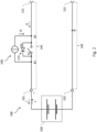
- FIG. 12 shows a schematic view of an energy storage device for a marine vehicle according to embodiments of the present disclosure.
- the energy storage device 100 comprises a first connection 111 and a second connection 112, and an energy storage unit 120 with a first pole 131 and a second pole 132, the first pole 131 being connected to the first connection 111 and the second pole 132 being connected to the second connection 112 is. More precisely, the first pole 132 is connected to the first connection 111 via a first connecting line 141 and the second pole 132 is connected to the second connection 112 via a second connecting line 142 .
- the energy storage unit 120 is set up to store electrical energy.
- the energy storage device 100 further comprises a first switching unit 171.
- the first switching unit 171 is arranged in the first connection line 141 between the first node K1 and the second node K2, i.e. it is connected to the first node K1 and the second node K2.
- the first switching unit 171 is configured to switch a current from the first node K1 to the second node K2.
- the first switching unit 171 can also be referred to as the first main switch.
- the energy storage device 100 is set up to be connected in an energy storage system 1000 for a watercraft (not shown) by means of the first connection 111 and the second connection 112 to at least one further energy storage device 100 ′ in a parallel circuit to become what's in figure 1 is illustrated by the first and second connections 111′, 112′ and connecting lines of the energy storage device 100′ shown in dashed lines.
- the energy storage system 1000 comprises two or more energy storage devices 100, 100' according to embodiments of the present disclosure, wherein the energy storage devices 100, 100 are connected to each other in parallel by means of the first and second terminals 111, 111', 112, 112'.
- the energy storage system 1000 is set up to supply electrical energy to an electrical load (not shown), for example an electric drive motor of the watercraft, using the electrical energy from the energy storage units 120 .
- the energy storage device 100 comprises a pre-charging circuit 150 and a control unit 160.
- the control unit 160 is configured to control the pre-charging circuit 150 in order to limit the strength of a discharge current I′ for the energy storage unit 120 to a predetermined discharge current threshold value.
- the pre-charging circuit 150 thus has the character of a (constant) current source in this respect.
- a compensating current between the energy storage devices 100, 100' connected to one another in parallel is possible, which is largely independent of the state of charge of the respective energy storage units 120. Accordingly, the pre-charge circuit 150 can be operated as a buck converter.
- the energy storage device 100 may further be configured not to limit the magnitude of a charging current I for the energy storage unit 120 or to limit the magnitude of the charging current I to a charging current threshold that is greater than the discharging current threshold.
- the charging current I is not limited or is limited to a threshold value which is greater than the threshold value for the discharging current I', the pre-charging circuit 150 can be used for a so-called asymmetric pre-charging of energy storage devices 100, 100' in an energy storage system 1000.
- the discharging current I' denotes a current from the energy storage unit 120 via the first pole 131, i.e. a current from the second pole 132 via the energy storage unit 120 to the first pole 131
- the charging current I denotes a current via the first pole 131 to the energy storage unit 120, i.e. a current from the first pole 131 via the energy storage unit 120 to the second pole 132.
- the energy storage unit 120 comprises according to in figure 1 embodiment shown one or more in figure 1 schematically indicated battery modules that are connected in series and / or in parallel.
- the battery module(s) each comprise one or more battery cells (not shown) connected in series and/or in parallel. Accordingly, the energy storage device 100 can be referred to as a battery and the energy storage system can be referred to as a battery system or battery bank.
- the battery cell or battery cells can be lithium-based, in particular lithium-ion-based.
- the battery module or modules are connected to the first and second poles 131, 132 of the energy storage unit 120 in order to provide or receive the electrical energy and a voltage U (see figure 3 ) between poles 131, 132.
- the poles 131, 132 have opposite polarity, the first pole 131 being the positive pole and the second pole 132 being the negative pole.
- the first pole 131 can form the cathode of the energy storage unit 120 and the second pole 132 can form the anode of the energy storage unit 120 in an idle state or during a discharging process of the energy storage unit 120 .
- the negative pole 132 may be connected to a ground of the energy storage device 100 and/or the energy storage system 100 .
- the voltage U can be positive.
- the voltage U can also be referred to as the voltage of the energy storage unit 120 .
- the energy storage unit 120 may be configured such that a value for a maximum possible charge current for the energy storage unit 120 is equal to or greater than (N-1) times the discharge current threshold. Also, the charging current threshold may be equal to or greater than (N-1) times the discharging current threshold.
- N represents the number of energy storage devices 100 connected in parallel in the energy storage system 1000. Thus, at N it is parallel switched, similar energy storage devices 100 in the energy storage system, it is possible for a single energy storage unit 120 to take up currents as charging current I, which the other N-1 energy storage units 120 can emit as respective discharge currents I' during the asymmetrical pre-charging, without the charging current I for this energy storage unit 120 has to be interrupted for safety reasons.
- the first connecting line 141 has a first node K1 connected to the first pole 131 and a second node K2 connected to the first terminal 111 .
- the second connection line 142 has a fourth node K4 which is connected to the second pole 132 and the second terminal 112 .
- the first terminal and the second terminal 111, 112 can be arranged on a housing (not shown) of the energy storage device 100 so that they are exposed to the outside and are therefore referred to as external terminals.
- FIG. 12 shows a schematic view of an energy storage device for a marine vehicle according to embodiments of the present disclosure. Based on figure 2 the current source character and the voltage source character of the precharge circuit are illustrated.
- the first switching unit 171 includes a first switch S1 and a first diode D1.
- the first switch S1 is connected to the first node K1 and the second node K2 and arranged to switch a current between the first node K1 and the second node K2 thereacross.
- the first diode D1 is connected to the first switch S1 in parallel, ie the first diode D1 is also connected to the first node K1 and the second node K2.
- the first diode D1 is reverse biased for current across from the first node K1 to the second node K2 and is forward biased for current across from the second node K2 to the first node K1. Accordingly, the anode of the first diode D1 is connected to the second node K2 and the cathode of the first diode D1 is connected to the first node K1.
- the first switching unit 171 is set up to switch, in particular to interrupt, a current from the first node K1 to the second node K2 via the first switching unit 171, but cannot be set up to switch a current from the second node K2 to the second node K2 due to the diode D1 to interrupt the first node K1 via the first switching unit 171.
- the first switching unit 171 can be implemented, for example, as a power switch, in particular as a power transistor, for example as a MOSFET, which is only for current in one direction (Forward direction) is capable of being blocked. For a current in the other direction, the opposite direction to this direction (reverse direction), the circuit breaker cannot be capable of blocking.
- the circuit breaker can also be described as reverse non-blocking.
- the circuit breaker can be blocking capable of flowing from the first node K1 to the second node K2 (forward direction) and therefore switch this current, and not capable of blocking a flow from the second node K2 to the first node K1 (reverse direction) and can therefore switch this current do not interrupt.
- the diode D1 is advantageously formed by the parasitic diode of the power transistor or MOSFET.
- a current I1 from the first connection 111 to the second node K2 and from the second node K2 via the first switching unit 171 and possibly via the pre-charging circuit 150 to the first node K1 can be essentially unlimited. From there, the current continues to flow to the first pole 131 and to the energy storage unit 120 as charging current I for charging the energy storage unit 120.
- This charging current I of the energy storage unit 120 is therefore not limited by the pre-charging circuit 50.
- a discharge current l' for discharging the energy storage unit 120 flows from the energy storage unit via the first pole 131 to the first node K1 and from there via the pre-charging circuit 150 as a current I2 to the second node K2 and to the first terminal 111.
- the pre-charging circuit 150 can use the current I2 and thus also limit the discharge current l'.
- the pre-charge circuit 150 acts as a current source in this regard.
- the discharge current I′ of the energy storage unit 120 can be limited by the pre-charging circuit 150 to a predefined discharge current limit value.
- the pre-charging circuit 150 can be designed as a regulated or clocked current source.
- the pre-charging circuit 150 therefore enables a current limitation for a discharge current I' of the energy storage unit 120 and/or no or a significantly higher current limitation for a charging current I of the energy storage unit 120.
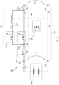
- FIG. 12 shows a schematic view of an energy storage device for a marine vehicle according to embodiments of the present disclosure.
- the energy storage device shown corresponds to that with reference to FIG figure 1 described energy storage device and shows further details thereof.
- the control unit 160 is in figure 3 Not shown.
- the pre-charge circuit 150 includes a third connection line 143 between the first node K1 and the second node K2, with a third node K3 and an inductor L between the third node K3 and the second node K2.
- the precharge circuit 150 further includes a fourth connection line 144 between the third node K3 and the fourth node K4, and a free wheeling diode D4 arranged in the fourth connection line 144 and arranged for a current I4 from the third node K3 to the fourth node K4 in the reverse direction and arranged for forward current from the fourth node K4 to the third node K3.
- the third connection line 143 comprises a first end that is connected or can be connected to the first node K1 and a second end that is connected or can be connected to the second node K2.
- the third node K3 is therefore arranged between the first end and the second end of the third connecting line 143 and the inductor L is arranged between the third node K3 and the second end of the third connecting line 143 .
- the fourth connecting line 144 thus comprises a first end which is connected to the third node K3 and a second end which is connected or can be connected to fourth node K4.
- the freewheeling diode D4 is therefore arranged in the fourth connecting line 144 between the first end and the second end of the fourth connecting line 144 and arranged for a current from the second end of the fourth connecting line 144 to the third node K3 or to the first end of the fourth connecting line 144 in the forward direction and is arranged for reverse flow from the third node K3 or from the first end of the fourth connection line 144 to the second end of the fourth connection line 144 .
- the pre-charging circuit 150 further comprises a third switching unit 173.
- the third switching unit 173 is arranged in the third connecting line 143 between the first node K1 or the first end of the third connecting line 143 and the third node K3, i.e. it is connected to the first node K1 and connected to the third node K3.
- the third switching unit 173 is set up to switch a current from the first node K1 or from the first end of the third connecting line 143 to the third node K3.
- the first switching unit 171 is therefore connected in parallel with the third connecting line 173 with the third switching unit 173 and the inductance L.
- the inductance L can be realized by a coil or the like.
- the energy storage device 100 also includes a second switching unit 172.
- the second switching unit 172 can also be referred to as a second main switch.
- the second switching unit 172 is arranged in the first connecting line 141 between the first node K1 and the first pole 131, ie it is connected to the first node K1 and the first pole 131.
- the second switching unit 172 for switching a current from the first node K1 to the first pole 131 set up.
- the arrangement of the second switching unit 172 is not on the arrangement of figure 2 limited.
- the second switching unit 172 can be arranged in the second connecting line 142 between the second pole 132 and the fourth node K4 and configured to switch a current from the second pole 132 to the fourth node K4.
- the control unit 160 which is figure 3 not shown, is set up to control the first switching unit 171 and the third switching unit 173, and can be set up in particular to switch the first switching unit 171 and the third switching unit 173 to increase the strength of the discharge current l' for the energy storage unit 120 via the first pole 131 and further to the first node K1 to a predetermined discharge current threshold value.
- the control unit 160 is also set up to switch the second switching unit 172 .
- the second switching unit 172 and the third switching unit 173 are constructed analogously to the first switching unit 171 .
- the second switching unit 172 includes a second switch S2 and a second diode D2.
- the second switch S2 is connected to the first node K1 and the first pole 131 and configured to switch a current between the first node K1 and the first pole 131 .
- the second diode D2 is connected to the second switch S2 in parallel, i.e. the second diode D2 is also connected to the first node K1 and the first pole 131.
- the second diode D2 is reverse biased for current across from the first node K1 to the first pole 131 and forward biased for current across from the first pole 131 to the first node K1.
- the second switching unit 172 is set up to switch a current I3 from the first node K1 to the first pole 131 .
- the third switching unit 173 includes a third switch S3 and a third diode D3.
- the third switch S3 is connected to the first node K1 and the third node K3 and configured to switch a current between the first node K1 and the third node K3.
- the third diode D3 is connected to the third switch S3 in parallel, ie the third diode D3 is also connected to the first node K1 and the third node K3.
- the third diode D3 is reverse biased for current across from the first node K1 to the third node K3 and is forward biased for current across the third node K3 to the first node K1 arranged.
- the third switching unit 173 is set up to switch a current from the first node K1 to the third node K3.
- the second switching unit 172 and the third switching unit 173 can be in the form of power switches, in particular in the form of a power transistor, preferably in the form of a MOSFET.
- the second diode D2 and the third diode D3 can preferably likewise be formed by the parasitic diode of the respective circuit breaker.
- the circuit breaker can be blockable for a current from the first node K1 to the first pole 131 (forward direction) and therefore switch this current, and the circuit breaker cannot for a current from the first pole 131 to the first node K1 (reverse direction). be blockable and therefore cannot interrupt this current.
- the circuit breaker can be blockable for a current from the first node K1 to the third node K3 (forward direction) and can therefore switch this current, and the circuit breaker cannot for a current from the third node K3 to the first node K1 (reverse direction). be blockable and therefore cannot interrupt this current.
- first to third switching units 171, 172, 173 are designed as power switches, in particular as MOSFETs, is in figure 4 illustrated.
- the control unit 160 can switch or control the charging current I from the first node K1 to the first pole 131 and to the energy storage unit 120 by means of the second switching unit 172 .
- control unit 160 can switch the second switching unit 172 in such a way, in particular by repeated and alternating opening and closing of the second switching unit 172, that a maximum value of the current intensity of the charging current I or a mean value over time of the current intensity is equal to or smaller than the specified charging current threshold value.
- the charging current I can be limited to the specified charging current threshold value.
- the discharge current I′ can also be interrupted by opening the first switching unit 171 and the third switching unit 173 .
- control unit 160 can switch or control the discharge current I′ from the energy storage unit 120 via the first pole 131 to the first node K1 by means of the first switching unit 171 and the third switching unit 173 .
- the discharge current I' can be limited to a predetermined discharge current threshold value.
- the energy storage device 100 can also include measuring devices for currents and voltages, which are not shown.
- the measuring devices can be set up to transmit the respectively measured currents or voltages to the control unit 160 .
- the control unit 160 can use the measured currents and voltages to perform control methods described below.
- Measuring a current may include determining whether a current is present in the corresponding direction, in particular whether a current magnitude thereof is greater than a predetermined lower threshold value, for example 0 A. Measuring the current may also include measuring an amperage. The measurement and transmission can be repeated and/or continuous.
- FIG. 12 shows a schematic view of a power storage device for a watercraft according to second embodiments of the present disclosure.
- the energy storage device 200 shown corresponds to that with reference to FIG figure 3 shown energy storage device 100 to the differences described below.
- the energy storage device 200 includes a fourth switching unit 174 arranged in the fourth connecting line 144 between the fourth node K4 and the third node K3. That is, the fourth switching unit 174 is connected to the fourth node K4 and the third node K3.
- the fourth switching unit 174 is arranged in the fourth connecting line 144 between the first end and the second end of the fourth connecting line 144 and is set up for switching a current from the third node K3 to the second end of the fourth connecting line 144.
- the fourth switching unit 174 is for switching a current set up from the third node K3 to the fourth node K4.
- the control unit 160 is also set up to switch the fourth switching unit 174 .
- the fourth switching unit 174 includes a fourth switch S4 and the freewheeling diode D4.
- the fourth switch S4 is connected to the third node K3 and the fourth node K4 and arranged to switch a current therebetween between the third node K3 and the fourth node K4.
- the freewheeling diode D4 is connected in parallel to the fourth switch S4, ie the freewheeling diode D4 is also connected to the third node K3 and the fourth node K4. Free wheeling diode D4 is reverse biased for current across from the third node K3 to the fourth node K4 and forward biased for current across from the fourth node K3 to the third node K3.
- the fourth switching unit 174 is configured to switch the current I4 from the third node K3 to the fourth node K4.
- the fourth switching unit 174 can be designed as a power switch, in particular as a power transistor, preferably as a MOSFET.
- the freewheeling diode D4 can be formed by the parasitic diode of the power switch. Accordingly, the circuit breaker can be blocking-capable for the current I4 from the third node K3 to the fourth node K4 (forward direction) and therefore switch this current, and the circuit-breaker can and cannot be blockable for a current from the fourth node K4 to the third node K3 (reverse direction). therefore do not interrupt this flow.
- the control unit 160 is configured to switch the first to fourth switching units 171, 172, 173, 174 to perform control methods for the energy storage device according to embodiments of the present disclosure.
- figure 7 12 shows a precharge control method according to embodiments of the present disclosure.
- the precharge control method can be used for those referred to Figure 1 to Figure 6 shown energy storage devices are performed.
- the pre-charge control method can be performed simultaneously for a plurality of, preferably all, energy storage devices of an energy storage system connected in parallel according to embodiments of the present disclosure.
- the fourth switching unit 174 With reference to the in figure 5 and figure 6 shown embodiments of the energy storage device 200 should the fourth switching unit 174 here to be open.
- the pre-charging control method is preferably carried out when the energy storage system, which is embodied as a battery bank, for example, is switched on.
- control unit 160 closes the third switching unit 173 and the second switching unit 172 in a first step S11.
- control unit 160 can initially open the first switching unit 171 or leave it open.
- a discharge current l' flows from the energy storage unit 120 via the first pole 131 and further via the second switching unit 172, the first node K1, the closed third switching unit 173, the third node K3 and the second node K2 to the first port 111.
- I2 is substantially equal to l'.
- This discharge current I' can be used to charge the other energy storage units 120 with a lower state of charge.
- a current I1 flows from the first connection 111 to the node K2.
- the current is divided according to the impedances of the connecting lines or current paths between K2 and K1 via the third switching unit 173 or via the first switching unit 171.
- the current continues to flow from K1 to the first pole 131 and further as a charging current I for the energy storage unit 120.
- I1 is essentially equal to I.
- the charging current I of one energy storage unit 120 is also equal to the discharging current l 'of the other energy storage unit 120.
- control unit 160 then executes precharge control processes according to the embodiments described below in a step S12.
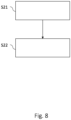
- figure 8 12 shows a precharge control method according to a first embodiment of the present disclosure.
- the precharge control method shown here can be used by the control unit in step S12 of figure 7 be performed.
- step S11 of FIG figure 7 determine whether a current I1 flows from the first terminal 111 to the second node K2, ie whether there is a current from the first terminal 111 to the second node K2.
- the control unit 160 determines whether the current intensity of the current I1 is greater than a predetermined lower threshold value, for example 0 A.
- the control unit 160 can determine whether a charging current I is present, or whether a current with the opposite direction to the current is present I2 is present. This is the case in particular when the energy storage unit 120 has a lower state of charge and therefore a lower voltage U in relation to the other energy storage units 120 in the energy storage system. In this case, the energy storage unit 120 is charged.
- control unit 160 closes first switching unit 171 in step S21. If first switching unit 171 and third switching unit 173 are MOSFETs, the current coming from node K2 commutes I1 largely via the first switching unit 171, i.e. on the first connecting line 141 between the second node K2 and the first node K1. This is due to the lower impedance of the MOSFET channel of the switched-on switching unit 171 in the first connection line 141 between the second node K2 and the first node K1 compared to that of the third connection line 143.
- control unit 160 can open the third switching unit 173 immediately after the closing of the first switching unit 171 .
- the energy stored in the inductance L can be dissipated via the third diode D3, which is formed by a MOSFET, for example.
- the energy storage unit 120 can be charged with a charging current I with a relatively large current intensity or with an unlimited charging current I through the pre-charging control method described here.
- figure 9 12 shows a pre-charge control method according to a second embodiment of the present disclosure.
- the pre-charge control method shown here can be executed by the control unit 160 in step S12 of FIG figure 7 be performed.
- control unit 160 opens third switching unit 173.
- control unit 160 closes third switching unit 173.
- step S11 of FIG figure 7 first determine whether a current I2 flows from the third node K3 to the second node K2, ie whether there is a current I2 from the third node K3 to the second node K2.
- the control unit 160 determines whether the current I2 is equal to or greater than a predetermined lower threshold value, for example 0 A.
- controller 160 may determine whether discharge current I' is present or whether a current of opposite direction to current I1 is present. This is the case in particular when the energy storage unit 120 has a higher state of charge and therefore a higher voltage U than the other energy storage units 120 in the energy storage system. In this case, the energy storage unit 120 is discharged.
- the control unit 160 may perform steps S31 and S32 when determining that a current I2 flows from the third node K3 to the second node K2.
- the third switching unit 173 By alternately opening and closing the third switching unit 173, it is possible to control the magnitude of the discharge current I'. For example, a maximum value or an average value over time of the current intensity can be controlled and, in particular, limited to the specified discharge current threshold value.
- control unit 160 is set up to repeatedly and alternately open and close the third switching unit 173, i.e. to repeatedly and alternately switch what is in figure 9 is illustrated by a double arrow between steps S31 and S32.
- the control unit 160 can limit the current strength of the discharge current I′ to the discharge current threshold value.
- the control unit 160 can in particular limit a mean value over time or a maximum value of the current strength of the discharge current I′ to the discharge current threshold value.
- the control unit can perform a pulse width modulation method for switching the third switching unit 173 alternately and repeatedly.
- an opening duration of the third switching unit 173 indicates a duration between opening and closing, ie the duration during which the third switching unit 173 is opened.
- a closing time of the third Switching unit 173 indicates a period of time between closing and opening, ie the period of time during which the third switching unit 173 is closed.
- a reciprocal of the sum of the opening duration and the closing duration can be defined as the switching frequency.
- a ratio between the dwell time and the sum of the open time and the dwell time may be defined as the duty cycle or duty cycle of the pulse width modulation scheme.
- a large duty cycle can correspond to a large pulse width and vice versa.
- a pulse width can correspond to the closing duration.
- the switching frequency and duty cycle are also referred to as precharge switching frequency and precharge duty cycle, respectively.
- the switching frequency, the closing duration, the opening duration and/or the pulse duty factor can be predetermined.
- these parameters can be specified or set by the control unit 160 and/or changed by the control unit 160 .
- the control unit 160 can be set up to change these parameters in stages and/or continuously.
- the control unit 160 can set the pulse duty factor in such a way that the mean value over time or maximum value of the current intensity of the discharge current I′ and/or the current I2 is limited to the discharge current threshold value.
- controller 160 may set the duty cycle or opening duration such that the average current I2 or discharge current I' is initially or limited to approximately 20 A, then is or is limited to approximately 15 A, and then approximately is or is limited to 10A. Accordingly, the pulse duty factor and/or the closing time is reduced in stages here.
- the switching frequency can be 100 kHz, for example.
- the control unit 160 can thus implement a linear limiting controller.
- control unit 160 opens the third switching unit 173 in step S31 if the current intensity of the discharge current I', the current I2 from the third node K3 to the second node K2 or the current in the opposite direction to the current I1 is greater than a predetermined first threshold value or exceeds this threshold.
- the current I2 through L then commutes via the fourth connecting line 144 and the freewheeling diode D4, whereupon the current I2 drops.
- the control unit 160 then closes the third switching unit 173 if the current strength is equal to or less than a predetermined second threshold value or this threshold value falls below As a result, the strength of the current I2 or the discharge current I' can rise again.
- the second threshold value can be equal to or smaller than the first threshold value.
- the control unit 160 can carry out a two-point control method or a hysteresis control method.
- the first threshold value can be equal to or greater than the discharge current threshold value.
- the maximum value or the mean value over time of the current strength of the discharge current I' or of the current I2 can be limited to the discharge current threshold value.
- control unit 160 closes the first switching unit 171 in a step S33 after step S32 if the current intensity of the current I2 from the third node K3 to the second node K2 and/or the discharge current I' is equal to or smaller than a predetermined third threshold value or falls below this threshold value and/or if a difference between the voltage U at the energy storage unit 120 and the voltage U1 at the terminals 111, 112 is equal to or smaller than a predetermined fourth threshold value or falls below this.
- the third threshold can be smaller than the first and/or second threshold.
- control unit 160 can open the third switching unit 173 immediately after the first switching unit 141 has closed.
- the control unit 160 can be set up to then leave the first switching unit 171 continuously closed, i.e. to no longer switch.
- the control unit 160 can leave the third switching unit 173 continuously open, i.e. no longer switching.
- the fourth threshold value can correspond to a maximum permissible voltage difference between the voltage U at the energy storage unit 120 and the voltage U1 at the terminals 111, 112.
- the first switching unit 171 as a main switch can be relieved by the precharge control method according to embodiments.
- the discharge current l' for the energy storage unit 120 via the precharging circuit 150 more precisely via the third connecting line 143 between the first node K1 and the third node K3, where it can be switched by the third switching unit 173.
- the strength of the discharge current I' can be limited to a predetermined discharge current threshold value.
- figure 10 12 shows a charging control method according to an embodiment of the present disclosure.
- the tax procedure can be related to figure 5 and figure 6 shown energy storage device are carried out.
- the charging control method can be used in particular for multiple or all energy storage devices connected in parallel of an energy storage system according to embodiments of the present disclosure may be performed simultaneously.
- the charging control method can also be referred to as a boost method or boost process.
- the charging control method shown here can be performed as part of or during a charging process for charging the energy storage unit 120 .
- the charging process can be carried out by an external charging device which is connected to the terminals 111, 112.
- the charging process can be a CCCV charging process.
- control unit 160 first closes the second switching unit 172 in an optional first step S41.
- the control unit 160 can also close the first switching unit 171 in this step.
- the closing of the first switching unit 171 can take place before, at the same time or after the closing of the second switching unit 172 .
- a current I1 provided by the external charging device can flow from the first connection 111 to the second node K2 and from there to the first pole 131 .
- the control unit 160 can also open the fourth switching unit 174 .
- a current I4 via the fourth connecting line 144 is thus initially prevented.
- control unit 160 can open the third switching unit 173 . If like with reference to figure 8 If the first and third switching units 171, 173 are designed as MOSFETs, due to the lower impedance of the MOSFET channel of the switched-on MOSFET 171, the current I1 coming from the node K2 largely commutes via the first switching unit 171, ie on the first connecting line 141 between the second Node K2 and the first node K1. However, the third switching unit 173 can also be closed.
- control unit 160 opens the first switching unit 171. This prevents a current flow via the first connecting line 141 from the first node K1 to the second node K2 in the subsequent steps.
- a third step S43 the control unit 160 closes the fourth switching unit 174. This enables a current I4 via the fourth connecting line 144 from the node K3 to the fourth node K4. This results in a current flow from the first connection 111 via the second node K2, the inductance L and the third node K3 and further via the fourth connecting line 144 to the fourth node K4. Thus, energy is stored in the inductance L in this phase.
- the control unit 160 then opens the fourth switching unit 174 in the fourth step S44.
- the current from the node K3 via the fourth connecting line 144 to the fourth node K4 thereby changes to the third connecting line 143 between the third node K3 and the first node K1.
- a current I3 flows further to the first pole 131 and further as a charging current I to the energy storage unit 120.
- the energy stored by the inductance L is thus released to the energy storage unit 120.
- the voltage U at the energy storage unit 120 is increased or maintained and the amperage of the charging current I for charging the energy storage unit 120 is increased or maintained.
- the switching unit 173 has the third switch S3 and the third diode D3, and if the switching unit 173 is designed in particular as a power switch, for example a MOSFET, the third diode D3 will take over the current from the node K3 after the opening of the fourth switching unit 174. In order to minimize losses, the control unit 160 can be set up to close the third switching unit 173 after the fourth switching unit 174 has opened.
- the control unit 160 can be set up to open the second switching unit 172 in an optional fifth step S45. As a result, the charging current I for the energy storage unit 120 is interrupted and the charging process can be ended. Control unit 160 preferably opens second switching unit 172 when the SOC of energy storage unit 120 has reached more than 99%, approximately or essentially 100% and/or when voltage U at energy storage unit 120 has reached a predetermined value. When the charging current I for the energy storage unit 120 is interrupted, it can be detected by the external charging device and the external charging device can stop charging.
- control unit 160 can open the first switching unit 171 according to step S42 and switch the fourth switching unit 174 according to steps S43 and S44 for the first time when the current I1 from the first connection 111 to the second node K2 and/or when the charging current I is equal to or smaller than a booster threshold value or falls below the booster threshold value and/or when the voltage U1 at the terminals 111, 112 and/or the voltage U at the energy storage unit 120 is greater than a predetermined charging voltage threshold value.
- the voltage U at the energy storage unit 120 can be maintained or increased by switching the fourth switching unit 174 . This also allows the amperage of the charging current I for the energy storage unit 120 maintained or increased. Accordingly, the pre-charging circuit 150 can be operated here as a step-up converter or boost converter.
- the boost converter can be easily implemented, since the freewheeling diode D4 can only be implemented by the parasitic diode of the fourth switching unit 174, in particular a power transistor such as a MOSFET, and the control unit 160 has to be set up to switch the fourth switching unit 174.
- the energy storage device 200 can thus carry out a kind of precision final charge of the energy storage unit 120 as required by the pre-charging circuit 150 .
- the targeted SOC of the energy storage unit 120 of 100% can be reliably achieved regardless of the type of installation.
- an external charging device can be used to charge the energy storage device 200 with negative tolerance.
- Negative tolerance means here that the external charging device changes from the constant voltage phase to the constant current phase when the voltage U1 at the terminals 111, 112 or a voltage U at the energy storage unit 120 reaches a value that is below the actual end-of-charge voltage of the Energy storage unit 120 is located. This value can also be referred to as the "internal end-of-charge voltage of the external charging device".
- an end-of-charge voltage of the energy storage unit 120 may be 30 V
- the internal end-of-charge voltage of the external charging device may be 29 V
- the charging voltage threshold at which the pre-charging circuit 150 starts switching the fourth switching unit 174 may be 28 V.
- a communication of the energy storage device 200 with the charging device is not necessary.
- External charging devices of any model and/or manufacturer that meet the charge shot voltage requirements of the energy storage unit 120 may be employed.
- the final final charge of the energy storage unit 120 can take place with higher power compared to charging with only the external charging device. This also simplifies connection in parallel configurations of battery banks.
- control unit 160 is set up in particular to carry out steps S43 and S44 alternately and/or repeatedly, which in figure 10 is illustrated by a double arrow between steps S43 and S44.
- the control unit 160 may be configured to repeat the fourth switching unit 174 according to the steps S43 and S44 and to close and open alternately, ie to switch repeatedly and alternately.
- the control unit 160 can be set up to repeatedly and alternately open and close the fourth switching unit 174 in such a way that a mean value over time or a minimum value of the current strength of the charging current I and/or the current I1 is transmitted via the first connecting line 141 from the first terminal 111 and to the second node K2 is equal to or greater than a booster threshold.
- the control unit 160 can in particular be set up to switch the fourth switching unit 174 repeatedly and alternately based on a predefined switching frequency and/or based on a predefined duty cycle, also referred to as clocked or periodic switching. As a result, the control unit 160 can carry out a pulse width modulation method for switching the fourth switching unit 174 .
- an opening duration of the fourth switching unit 174 indicates a duration between the opening and the closing, that is to say the duration during which the fourth switching unit 174 is open.
- a closing duration of fourth switching unit 174 indicates a duration between closing and opening, ie the duration during which fourth switching unit 174 is closed.
- a reciprocal of the sum of the opening duration and the closing duration can be defined as the switching frequency of the fourth switching unit 174 .
- a ratio between the dwell time and the sum of the open time and the dwell time may be defined as the duty cycle or duty cycle of the pulse width modulation scheme for the fourth switching unit 174 .
- a large pulse duty factor can correspond to a large pulse width and vice versa.
- a pulse width can correspond to the closing duration of the fourth switching unit 174 .
- the switching frequency can be approximately 100 kHz, for example.
- the switching frequency, the closing duration, the opening duration and/or the pulse duty factor can be predefined. In particular, these parameters can be specified or set by the control unit 160 and/or changed by the control unit 160 .
- the control unit 160 can be set up to change these parameters in stages and/or continuously. With reference to the in figure 10 described charging control method, the switching frequency and the duty cycle are also referred to as charging switching frequency and charging duty cycle.
- the control unit 160 can also carry out a two-point control method or a hysteresis control method.
- the control unit 160 can be set up to close the fourth switching unit 174 in the third step S43 if the amperage of the current I1 from the first connection 111 to the second node K2 or the charging current I is less than a predetermined first charging threshold value or exceeds this threshold value .
- the control unit 160 may be set up to open the fourth switching unit 174 in the fourth step S44 if the current strength is equal to or greater than one predetermined second charging threshold or exceeds it.
- the second charging threshold value can be equal to or greater than the first charging threshold value.
- the first threshold value can be equal to or smaller than a booster threshold value. Accordingly, the minimum value or the mean value over time of the current strength of the charging current I or of the current I1 can be maintained at the booster threshold value.
- the control unit 160 can be set up to reduce the booster threshold value, the closing duration and/or the duty cycle or the first charging threshold value and/or the second charging threshold value while the charging control method is being carried out or during the charging process.
- the effect of the voltage increase at the energy storage unit 120 can be gradually reduced or the minimum value or the mean value over time of the current intensity of the charging current I can be gradually reduced as a result.
- the booster effect of the charging control method or the pre-charging circuit 150 can be reduced as the SOC of the energy storage unit 120 increases.
- the value of a maximum current that the third switching unit 173 can carry and switch at maximum can be referred to as the current-carrying capacity of the third switching unit 173 .
- the current carrying capacity of the third switching unit 173 can correspond to approximately one tenth of the current carrying capacity of the first switching unit 171 and/or the second switching unit 172. According to embodiments, the current carrying capacity of the third switching unit 173 can correspond to the booster threshold value and/or the discharge current threshold value.
- the control units of the respective energy storage devices can communicate with each other.
- the pre-charge control method according to embodiments of the present disclosure is being performed for at least one of the energy storage devices, it can thereby be ensured that the charge control method is not performed for the other energy storage devices.
- this can prevent one or more energy storage devices from being discharged while the boost process is being carried out for the other energy storage devices at the same time.
- the pre-charging circuit according to embodiments of the present invention can therefore be used as a DC/DC converter, ie both as a buck converter and as a boost converter, and enables current limitation for discharge currents the energy storage unit or currents from the Energy storage device ("forward"), in particular for pre-charging. Balancing between energy storage devices connected in parallel can be performed for as long as necessary.
- the precharging circuit can limit a discharge current to 6A and/or an output power of 250W, in particular for loads without their own limiting circuit (so-called “dumb loads”). Short circuits can also be detected with the pre-charging circuit.
- the pre-charging circuit makes it possible to provide a 12V output ("forward") (see figure 1 ) to charge 12V board systems of a watercraft, for example.
- the 12V output can also be used as an input for currents (“backward”), for example for solar charging or for emergency applications.
- the pre-charge circuit also acts as a DC/DC converter, enabling voltage stabilization in the event of sudden internal switch-off conditions, for example an emergency stop signal.
Landscapes
- Engineering & Computer Science (AREA)
- General Chemical & Material Sciences (AREA)
- Chemical & Material Sciences (AREA)
- Chemical Kinetics & Catalysis (AREA)
- Electrochemistry (AREA)
- Power Engineering (AREA)
- Manufacturing & Machinery (AREA)
- Life Sciences & Earth Sciences (AREA)
- Sustainable Development (AREA)
- Sustainable Energy (AREA)
- Transportation (AREA)
- Mechanical Engineering (AREA)
- Microelectronics & Electronic Packaging (AREA)
- Charge And Discharge Circuits For Batteries Or The Like (AREA)
Applications Claiming Priority (1)
| Application Number | Priority Date | Filing Date | Title |
|---|---|---|---|
| DE102021126882.6A DE102021126882A1 (de) | 2021-10-15 | 2021-10-15 | Energiespeichervorrichtung, Energiespeichersystem mit derselben und Steuerverfahren, Voraufladeschaltung für eine Energiespeichervorrichtung |
Publications (1)
| Publication Number | Publication Date |
|---|---|
| EP4167429A1 true EP4167429A1 (fr) | 2023-04-19 |
Family
ID=83898512
Family Applications (1)
| Application Number | Title | Priority Date | Filing Date |
|---|---|---|---|
| EP22201996.0A Pending EP4167429A1 (fr) | 2021-10-15 | 2022-10-17 | Dispositif de stockage d'énergie, système de stockage d'énergie le comprenant et procédé de commande, circuit de précharge pour dispositif de stockage d'énergie |
Country Status (4)
| Country | Link |
|---|---|
| US (1) | US20230128816A1 (fr) |
| EP (1) | EP4167429A1 (fr) |
| CN (1) | CN115986863A (fr) |
| DE (1) | DE102021126882A1 (fr) |
Families Citing this family (1)
| Publication number | Priority date | Publication date | Assignee | Title |
|---|---|---|---|---|
| US12609539B2 (en) | 2024-10-16 | 2026-04-21 | Lg Energy Solution, Ltd. | Switch mode pre-charge circuit |
Citations (3)
| Publication number | Priority date | Publication date | Assignee | Title |
|---|---|---|---|---|
| US20120139479A1 (en) * | 2010-12-01 | 2012-06-07 | Hanseok Yun | Charge control system of battery pack |
| US20170047758A1 (en) * | 2014-02-14 | 2017-02-16 | Commissariat A L'energie Atomique Et Aux Energies Alternatives | Dc voltage supply system configured to precharge a smoothing capacitor before supplying a load |
| CN111434509A (zh) * | 2019-01-11 | 2020-07-21 | 福特全球技术公司 | 针对逆变器直流侧电容器的集成充电和放电解决方案 |
Family Cites Families (10)
| Publication number | Priority date | Publication date | Assignee | Title |
|---|---|---|---|---|
| US6864669B1 (en) * | 2002-05-02 | 2005-03-08 | O2Micro International Limited | Power supply block with simplified switch configuration |
| US6850039B2 (en) * | 2003-05-02 | 2005-02-01 | O2Micro International Limited | Battery pack and a battery charging/discharging circuit incorporating the same |
| JP4894656B2 (ja) * | 2007-07-13 | 2012-03-14 | トヨタ自動車株式会社 | 車両 |
| DE102012219488A1 (de) | 2012-10-25 | 2014-04-30 | Robert Bosch Gmbh | Schaltungsanordnung und Verfahren zum Vorladen eines kapazitiven Bauelements |
| FR2998108B1 (fr) * | 2012-11-12 | 2014-12-19 | Accumulateurs Fixes | Systeme de pre-charge d'une capacite par une batterie |
| CN103066666B (zh) * | 2013-01-22 | 2015-08-26 | 矽力杰半导体技术(杭州)有限公司 | 一种升压型电池充电管理系统及其控制方法 |
| US9925878B2 (en) * | 2013-09-26 | 2018-03-27 | Ford Global Technologies, Llc | Bus pre-charge control using a buck converter |
| KR102056876B1 (ko) * | 2017-09-25 | 2019-12-17 | 주식회사 엘지화학 | 배터리 관리 장치와 이를 포함하는 배터리 팩 및 자동차 |
| CN111525646A (zh) * | 2020-04-30 | 2020-08-11 | 深圳传音控股股份有限公司 | 充电电路、方法、装置及电子设备 |
| JP2024531098A (ja) * | 2021-08-12 | 2024-08-29 | ミルウォーキー エレクトリック ツール コーポレイション | 電動工具バッテリパックのための電力供給調整器 |
-
2021
- 2021-10-15 DE DE102021126882.6A patent/DE102021126882A1/de active Pending
-
2022
- 2022-10-14 US US17/966,102 patent/US20230128816A1/en active Pending
- 2022-10-17 CN CN202211266378.7A patent/CN115986863A/zh active Pending
- 2022-10-17 EP EP22201996.0A patent/EP4167429A1/fr active Pending
Patent Citations (3)
| Publication number | Priority date | Publication date | Assignee | Title |
|---|---|---|---|---|
| US20120139479A1 (en) * | 2010-12-01 | 2012-06-07 | Hanseok Yun | Charge control system of battery pack |
| US20170047758A1 (en) * | 2014-02-14 | 2017-02-16 | Commissariat A L'energie Atomique Et Aux Energies Alternatives | Dc voltage supply system configured to precharge a smoothing capacitor before supplying a load |
| CN111434509A (zh) * | 2019-01-11 | 2020-07-21 | 福特全球技术公司 | 针对逆变器直流侧电容器的集成充电和放电解决方案 |
Also Published As
| Publication number | Publication date |
|---|---|
| DE102021126882A1 (de) | 2023-04-20 |
| US20230128816A1 (en) | 2023-04-27 |
| CN115986863A (zh) | 2023-04-18 |
Similar Documents
| Publication | Publication Date | Title |
|---|---|---|
| EP3137335B1 (fr) | Commande pour véhicule à entraînement électrique, véhicule à entraînement électrique comportant une commande et procédé | |
| EP2953227B1 (fr) | Réseau de bord pour un véhicule automobile | |
| DE102008054885B4 (de) | Vorrichtung und Verfahren zum Steuern einer Energieversorgung eines Bordnetzes eines Fahrzeugs | |
| EP1784910B1 (fr) | Regulateur de tension a protection contre les surtensions | |
| DE102016005565B4 (de) | Schaltungsanordnung für eine Zwischenkreiskapazität, Kraftfahrzeug mit einer solchen Schaltungsanordnung sowie Verfahren zum Vorladen einer Zwischenkreiskapazität und Verfahren zum Ausgleichen von Batterieladezuständen parallel geschalteter Batteriemodule | |
| EP3092150B1 (fr) | Accumulateur d'énergie électrochimique et procédé d'équilibrage | |
| DE102011109198A1 (de) | Combined heating and pre-charging function and hardware for propulsion batteries | |
| DE102010051323B4 (de) | Ladesystem zum Laden einer Batterie eines Fahrzeuges mit einem Zwei-Weg-Laderegler | |
| DE102015117744A1 (de) | Batteriesystem | |
| DE102012219488A1 (de) | Schaltungsanordnung und Verfahren zum Vorladen eines kapazitiven Bauelements | |
| DE102019201606A1 (de) | Verfahren zum elektrischen Vorladen eines Zwischenkreiskondensators im Hochvoltsystem eines zumindest teilweise elektrisch angetriebenen Kraftfahrzeugs sowie ein derartiges Hochvoltsystem | |
| WO2016091426A1 (fr) | Dispositif permettant de charger une unité batterie et de faire fonctionner une unité de charge par l'intermédiaire d'un onduleur | |
| EP2532042B1 (fr) | Batterie à équilibrage inductif des cellules | |
| DE102019007868A1 (de) | Speichereinrichtung für ein elektrisch betriebenes Fahrzeug, sowie entsprechendes Verfahren zum Betreiben solch einer Speichereinrichtung | |
| EP2582009A1 (fr) | Système de stockage d'énergie avec algorithme de réglage implémenté et procédé de commande de l'état de chargement de ses éléments | |
| EP4167429A1 (fr) | Dispositif de stockage d'énergie, système de stockage d'énergie le comprenant et procédé de commande, circuit de précharge pour dispositif de stockage d'énergie | |
| AT510117A1 (de) | Batteriemodul | |
| DE102017220287B4 (de) | Kraftfahrzeug mit einem Energiespeicher sowie Verfahren zum Betreiben eines Kraftfahrzeugs | |
| DE102015208568B4 (de) | Bordnetz-Schaltmodul, Bordnetzunterstützungseinrichtung und Bordnetzzweig | |
| WO2023134946A1 (fr) | Dispositif de décharge (profonde) d'unités de batterie (de véhicule) | |
| DE102010001422A1 (de) | Batterie mit induktivem Cell-Balancing | |
| AT524263B1 (de) | Batterievorrichtung mit schaltbaren Batteriemodulen | |
| DE102009048587A1 (de) | Vorrichtung und Verfahren zum Steuern eines Ladestroms in einen Akkumulator sowie Energiespeichersystem | |
| EP4578092A1 (fr) | Procédé de fonctionnement d'un convertisseur indirect pour charger un condensateur de liaison à courant continu | |
| WO2023104622A1 (fr) | Batterie de véhicule |
Legal Events
| Date | Code | Title | Description |
|---|---|---|---|
| PUAI | Public reference made under article 153(3) epc to a published international application that has entered the european phase |
Free format text: ORIGINAL CODE: 0009012 |
|
| STAA | Information on the status of an ep patent application or granted ep patent |
Free format text: STATUS: THE APPLICATION HAS BEEN PUBLISHED |
|
| AK | Designated contracting states |
Kind code of ref document: A1 Designated state(s): AL AT BE BG CH CY CZ DE DK EE ES FI FR GB GR HR HU IE IS IT LI LT LU LV MC ME MK MT NL NO PL PT RO RS SE SI SK SM TR |
|
| P01 | Opt-out of the competence of the unified patent court (upc) registered |
Effective date: 20230613 |
|
| RAP3 | Party data changed (applicant data changed or rights of an application transferred) |
Owner name: TORQEEDO GMBH |
|
| STAA | Information on the status of an ep patent application or granted ep patent |
Free format text: STATUS: REQUEST FOR EXAMINATION WAS MADE |
|
| 17P | Request for examination filed |
Effective date: 20230919 |
|
| RBV | Designated contracting states (corrected) |
Designated state(s): AL AT BE BG CH CY CZ DE DK EE ES FI FR GB GR HR HU IE IS IT LI LT LU LV MC ME MK MT NL NO PL PT RO RS SE SI SK SM TR |
|
| STAA | Information on the status of an ep patent application or granted ep patent |
Free format text: STATUS: EXAMINATION IS IN PROGRESS |
|
| 17Q | First examination report despatched |
Effective date: 20250120 |
|
| REG | Reference to a national code |
Ref country code: DE Ref legal event code: R079 Free format text: PREVIOUS MAIN CLASS: H02J0007000000 Ipc: H02J0007620000 |
|
| GRAP | Despatch of communication of intention to grant a patent |
Free format text: ORIGINAL CODE: EPIDOSNIGR1 |
|
| STAA | Information on the status of an ep patent application or granted ep patent |
Free format text: STATUS: GRANT OF PATENT IS INTENDED |
|
| RIC1 | Information provided on ipc code assigned before grant |
Ipc: H02J 7/62 20260101AFI20260304BHEP Ipc: H02J 7/60 20260101ALI20260304BHEP |
|
| INTG | Intention to grant announced |
Effective date: 20260320 |