EP4169643A1 - Outil et procédé de production d'outil - Google Patents
Outil et procédé de production d'outil Download PDFInfo
- Publication number
- EP4169643A1 EP4169643A1 EP21829115.1A EP21829115A EP4169643A1 EP 4169643 A1 EP4169643 A1 EP 4169643A1 EP 21829115 A EP21829115 A EP 21829115A EP 4169643 A1 EP4169643 A1 EP 4169643A1
- Authority
- EP
- European Patent Office
- Prior art keywords
- recess
- tool
- tool according
- less
- protrusions
- Prior art date
- Legal status (The legal status is an assumption and is not a legal conclusion. Google has not performed a legal analysis and makes no representation as to the accuracy of the status listed.)
- Pending
Links
Images






Classifications
-
- B—PERFORMING OPERATIONS; TRANSPORTING
- B23—MACHINE TOOLS; METAL-WORKING NOT OTHERWISE PROVIDED FOR
- B23C—MILLING
- B23C5/00—Milling-cutters
- B23C5/02—Milling-cutters characterised by the shape of the cutter
- B23C5/10—Shank-type cutters, i.e. with an integral shaft
- B23C5/1009—Ball nose end mills
-
- B—PERFORMING OPERATIONS; TRANSPORTING
- B23—MACHINE TOOLS; METAL-WORKING NOT OTHERWISE PROVIDED FOR
- B23B—TURNING; BORING
- B23B27/00—Tools for turning or boring machines; Tools of a similar kind in general; Accessories therefor
- B23B27/14—Cutting tools of which the bits or tips or cutting inserts are of special material
-
- B—PERFORMING OPERATIONS; TRANSPORTING
- B23—MACHINE TOOLS; METAL-WORKING NOT OTHERWISE PROVIDED FOR
- B23B—TURNING; BORING
- B23B27/00—Tools for turning or boring machines; Tools of a similar kind in general; Accessories therefor
- B23B27/14—Cutting tools of which the bits or tips or cutting inserts are of special material
- B23B27/18—Cutting tools of which the bits or tips or cutting inserts are of special material with cutting bits or tips or cutting inserts rigidly mounted, e.g. by brazing
- B23B27/20—Cutting tools of which the bits or tips or cutting inserts are of special material with cutting bits or tips or cutting inserts rigidly mounted, e.g. by brazing with diamond bits or cutting inserts
-
- B—PERFORMING OPERATIONS; TRANSPORTING
- B23—MACHINE TOOLS; METAL-WORKING NOT OTHERWISE PROVIDED FOR
- B23C—MILLING
- B23C5/00—Milling-cutters
- B23C5/02—Milling-cutters characterised by the shape of the cutter
- B23C5/10—Shank-type cutters, i.e. with an integral shaft
-
- B—PERFORMING OPERATIONS; TRANSPORTING
- B23—MACHINE TOOLS; METAL-WORKING NOT OTHERWISE PROVIDED FOR
- B23K—SOLDERING OR UNSOLDERING; WELDING; CLADDING OR PLATING BY SOLDERING OR WELDING; CUTTING BY APPLYING HEAT LOCALLY, e.g. FLAME CUTTING; WORKING BY LASER BEAM
- B23K26/00—Working by laser beam, e.g. welding, cutting or boring
- B23K26/36—Removing material
- B23K26/362—Laser etching
-
- B—PERFORMING OPERATIONS; TRANSPORTING
- B23—MACHINE TOOLS; METAL-WORKING NOT OTHERWISE PROVIDED FOR
- B23K—SOLDERING OR UNSOLDERING; WELDING; CLADDING OR PLATING BY SOLDERING OR WELDING; CUTTING BY APPLYING HEAT LOCALLY, e.g. FLAME CUTTING; WORKING BY LASER BEAM
- B23K26/00—Working by laser beam, e.g. welding, cutting or boring
- B23K26/36—Removing material
- B23K26/362—Laser etching
- B23K26/364—Laser etching for making a groove or trench, e.g. for scribing a break initiation groove
-
- B—PERFORMING OPERATIONS; TRANSPORTING
- B23—MACHINE TOOLS; METAL-WORKING NOT OTHERWISE PROVIDED FOR
- B23K—SOLDERING OR UNSOLDERING; WELDING; CLADDING OR PLATING BY SOLDERING OR WELDING; CUTTING BY APPLYING HEAT LOCALLY, e.g. FLAME CUTTING; WORKING BY LASER BEAM
- B23K26/00—Working by laser beam, e.g. welding, cutting or boring
- B23K26/36—Removing material
- B23K26/40—Removing material taking account of the properties of the material involved
- B23K26/402—Removing material taking account of the properties of the material involved involving non-metallic material, e.g. isolators
-
- B—PERFORMING OPERATIONS; TRANSPORTING
- B23—MACHINE TOOLS; METAL-WORKING NOT OTHERWISE PROVIDED FOR
- B23P—METAL-WORKING NOT OTHERWISE PROVIDED FOR; COMBINED OPERATIONS; UNIVERSAL MACHINE TOOLS
- B23P15/00—Making specific metal objects by operations not covered by a single other subclass or a group in this subclass
- B23P15/28—Making specific metal objects by operations not covered by a single other subclass or a group in this subclass cutting tools
- B23P15/34—Making specific metal objects by operations not covered by a single other subclass or a group in this subclass cutting tools milling cutters
-
- B—PERFORMING OPERATIONS; TRANSPORTING
- B23—MACHINE TOOLS; METAL-WORKING NOT OTHERWISE PROVIDED FOR
- B23C—MILLING
- B23C2210/00—Details of milling cutters
- B23C2210/54—Configuration of the cutting part
-
- B—PERFORMING OPERATIONS; TRANSPORTING
- B23—MACHINE TOOLS; METAL-WORKING NOT OTHERWISE PROVIDED FOR
- B23C—MILLING
- B23C2226/00—Materials of tools or workpieces not comprising a metal
- B23C2226/12—Boron nitride
- B23C2226/125—Boron nitride cubic [CBN]
-
- B—PERFORMING OPERATIONS; TRANSPORTING
- B23—MACHINE TOOLS; METAL-WORKING NOT OTHERWISE PROVIDED FOR
- B23C—MILLING
- B23C2226/00—Materials of tools or workpieces not comprising a metal
- B23C2226/31—Diamond
- B23C2226/315—Diamond polycrystalline [PCD]
-
- B—PERFORMING OPERATIONS; TRANSPORTING
- B23—MACHINE TOOLS; METAL-WORKING NOT OTHERWISE PROVIDED FOR
- B23K—SOLDERING OR UNSOLDERING; WELDING; CLADDING OR PLATING BY SOLDERING OR WELDING; CUTTING BY APPLYING HEAT LOCALLY, e.g. FLAME CUTTING; WORKING BY LASER BEAM
- B23K2101/00—Articles made by soldering, welding or cutting
- B23K2101/20—Tools
-
- B—PERFORMING OPERATIONS; TRANSPORTING
- B23—MACHINE TOOLS; METAL-WORKING NOT OTHERWISE PROVIDED FOR
- B23K—SOLDERING OR UNSOLDERING; WELDING; CLADDING OR PLATING BY SOLDERING OR WELDING; CUTTING BY APPLYING HEAT LOCALLY, e.g. FLAME CUTTING; WORKING BY LASER BEAM
- B23K2103/00—Materials to be soldered, welded or cut
- B23K2103/50—Inorganic materials other than metals or composite materials
-
- G—PHYSICS
- G01—MEASURING; TESTING
- G01B—MEASURING LENGTH, THICKNESS OR SIMILAR LINEAR DIMENSIONS; MEASURING ANGLES; MEASURING AREAS; MEASURING IRREGULARITIES OF SURFACES OR CONTOURS
- G01B5/00—Measuring arrangements characterised by the use of mechanical techniques
- G01B5/28—Measuring arrangements characterised by the use of mechanical techniques for measuring roughness or irregularity of surfaces
Definitions
- the present disclosure relates to a tool and a method of manufacturing the tool.
- PTL 1 Japanese Patent Laying-Open No. 2017-119333 discloses a ball end mill.
- the ball end mill in PTL 1 has a main body portion and an edge portion.
- the edge portion is attached to a tip end of the main body portion.
- the edge portion is formed of a diamond sintered material containing diamond particles and a binder.
- the edge portion has a hemispherical shape.
- the surface of the edge portion includes recesses and protrusions.
- a tool of the present disclosure includes a tip end portion.
- the tip end portion has a surface. At least a part of the surface includes a plurality of protrusions, a first recess provided by contact between ends of two adjacent protrusions of the protrusions, and a second recess different from the first recess.
- the second recess is provided inside each of the protrusions or provided to extend across the two adjacent protrusions.
- the ball end mill disclosed in PTL 1 still has room for improvement in terms of contact with a workpiece.
- the present disclosure has been made in view of the above-described problem of the conventional art. More specifically, the present disclosure provides a tool improved in terms of contact with a workpiece.
- the tool of the present disclosure allows improvement in terms of contact with a workpiece.
- the tool according to the first embodiment is a cutting tool for cutting a workpiece. More specifically, the tool according to the first embodiment is a ball end mill 100.
- the workpiece is made of a cemented carbide, for example.
- Fig. 1 is a side view of ball end mill 100.
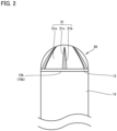
- Fig. 2 is an enlarged view of a region II in Fig. 1 .
- ball end mill 100 has a rotation axis A.
- Ball end mill 100 is rotated around a rotation axis A to process a workpiece.
- Ball end mill 100 has a main body portion 10 and a tip end portion 20.
- Main body portion 10 is formed of a cemented carbide, for example.
- Main body portion 10 has a first end 10a and a second end 10b in the direction along rotation axis A. Second end 10b is located opposite to first end 10a.
- Main body portion 10 has a shank 11 and a neck 12. Shank 11 is located on the first end 10a side, and neck 12 is located on the second end 10b side.
- Shank 11 extends along rotation axis A.
- Shank 11 has a first end 11a and a second end 11b in the direction along rotation axis A.
- First end 11a aligns with first end 10a.
- Second end 11b is located opposite to first end 11a.
- Shank 11 has a circular shape in a cross-sectional view taken along a line orthogonal to rotation axis A.
- Neck 12 extends from second end 11b along rotation axis A.
- Neck 12 has a first end 12a and a second end 12b in the direction along rotation axis A.
- First end 12a is located on the shank 11 side.
- Second end 12b is located opposite to first end 12a and aligns with second end 10b.
- Neck 12 has a circular shape in a cross-sectional view taken along a line orthogonal to rotation axis A. In a cross-sectional view taken along a line orthogonal to rotation axis A, neck 12 is smaller in cross-sectional area than shank 11.
- Tip end portion 20 is attached to main body portion 10, for example, by brazing. More specifically, tip end portion 20 is attached to second end 10b with a connection layer 13 interposed therebetween. Connecting layer 13 is made of a brazing material.
- Tip end portion 20 is formed of a nano-polycrystalline diamond.
- a nano-polycrystalline diamond contains a plurality of diamond crystal grains.
- the remainder of the nano-polycrystalline diamond may contain graphite and inevitable impurities, but does not contain a binder.
- the diamond crystal grains are directly bonded to each other. It is more preferable that inevitable impurities are smaller in amount, but such inevitable impurities may be contained in amount of several percent with respect to the total mass.
- the average grain size of the diamond crystal grains is less than 1 ⁇ m. In the nano-polycrystalline diamond, the average grain size of the diamond crystal grains is preferably 10 nm or more and 500 nm or less. In the nano-polycrystalline diamond, the average grain size of the diamond crystal grains may be 100 nm or more and 500 nm or less, or may be 100 nm or more and 300 nm or less.
- the average grain size of the diamond crystal grains in the nano-polycrystalline diamond can be measured in the following manner. Specifically, the surface of tip end portion 20 is precisely polished and then observed, for example, using an electron microscope such as JSM-7800F manufactured by JEOL Ltd., on the observation conditions allowing the grain boundaries to be visible, to thereby obtain a reflection electron microscope image and then analyze the obtained image. Thus, the average grain size of the diamond crystal grains can be measured.
- the nano-polycrystalline diamond preferably contains atoms belonging to Group 13 or Group 15 in the long periodic table.
- the atoms belonging to Group 13 in the long periodic table are boron atoms, for example.
- the atoms belonging to Group 15 in the long periodic table are nitrogen atoms, for example.
- the nano-polycrystalline diamond additionally contains the atoms belonging to Group 13 or Group 15 in the long periodic table, and thus, becomes electrically conductive.
- Tip end portion 20 may be formed of binderless cubic boron nitride.
- the binderless cubic boron nitride contains a plurality of cubic boron nitride crystal grains.
- the remainder of the binderless cubic boron nitride may contain boron nitride having another crystal structure (wurtzite type boron nitride, hexagonal boron nitride) and inevitable impurities, but does not contain a binder.
- the plurality of cubic boron nitride crystal grains are directly bonded to each other.
- boron nitride having another crystal structure (wurtzite type boron nitride, hexagonal boron nitride) and inevitable impurities are smaller in amount, but such boron nitride and inevitable impurities may be contained in amount of several percent with respect to the total mass.
- the average grain size of the cubic boron nitride crystal grains is less than 1 ⁇ m.
- the average grain size of the cubic boron nitride crystal grains is preferably 10 nm or more and 500 nm or less.
- the average grain size of the cubic boron nitride crystal grains may be 100 nm or more and 500 nm or less, or may be 100 nm or more and 300 nm or less. Note that the average grain size of the cubic boron nitride crystal grains is measured by the same method as that of measuring the average grain size of the diamond crystal grains.
- Tip end portion 20 has a surface 21.
- Tip end portion 20 has a hemispherical shape.
- surface 21 includes a partial spherical surface 21a. It is assumed that a diameter R represents the diameter of the hemisphere forming tip end portion 20.
- surface 21 (partial spherical surface 21a) contacts the workpiece.
- Surface 21 includes a groove 21b.
- Surface 21 is recessed in groove 21b.
- Groove 21b extends radially from the area in the vicinity of a central portion of surface 21.
- the ridgeline between groove 21b and partial spherical surface 21a forms a cutting edge 21c.
- Partial spherical surface 21a serves as a flank face.
- the surface of groove 21b contiguous to cutting edge 21c serves as a rake face.
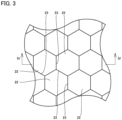
- Fig. 3 is a schematic plan view of partial spherical surface 21a of ball end mill 100.
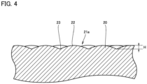
- Fig. 4 is a cross-sectional view taken along a line IV-IV in Fig. 3 .
- a plurality of protrusions 22 are formed on partial spherical surface 21a. Partial spherical surface 21a is recessed in each protrusion 22.
- each protrusion 22 has a hexagonal shape in a plan view (when viewed in the direction orthogonal to partial spherical surface 21a), but the planar shape of each protrusion 22 is not limited thereto.
- Protrusions 22 are formed, for example, entirely over partial spherical surface 21a. Protrusions 22 may be formed only in a part of partial spherical surface 21a.
- Partial spherical surface 21a is provided with a first recess 23.
- First recess 23 is provided by contact between ends of two adjacent protrusions 22.
- Protrusion 22 has a height H.
- Height H represents a distance between the tip end of protrusion 22 and the bottom of first recess 23.
- Height H is preferably 0.05 ⁇ m or more and 20 ⁇ m or less.
- the arithmetic mean height (Sa) of partial spherical surface 21a in each protrusion 22 is preferably 0.05 ⁇ m or more and 5 ⁇ m or less.
- the arithmetic mean height of partial spherical surface 21a in each protrusion 22 is measured according to JIS standard (JIS B 0681-2:2018).
- the skewness (Ssk) at partial spherical surface 21a in the portion provided with protrusions 22 and first recesses 23 is preferably less than 0 (a negative value).
- the skewness at partial spherical surface 21a in the portion provided with protrusions 22 and first recesses 23 is measured according to JIS standard (JIS B 0681-2:2018).
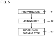
- Fig. 5 is a flowchart illustrating the method of manufacturing ball end mill 100. As shown in Fig. 5 , a preparing step S1, a joining step S2, and a protrusion forming step S3 are included.
- preparing step S1 members constituting main body portion 10 and tip end portion 20 are prepared. Note that protrusion 22 and first recess 23 are not provided on surface 21 (partial spherical surface 21a) of tip end portion 20 prepared in preparing step S1.
- joining step S2 main body portion 10 and tip end portion 20 are joined, for example, by brazing.
- protrusion 22 is formed.
- Protrusion 22 is formed by irradiating surface 21 (partial spherical surface 21a) with laser.
- First recess 23 is provided by contact between the ends of two adjacent protrusions 22.
- protrusions 22 are formed in protrusion forming step S3, and thereby, each first recess 23 is also provided.
- first recess 23 the ends of two protrusions 22 are in contact with each other to thereby provide first recess 23.
- swarf and the like produced from the workpiece are less likely to be restrained in first recess 23, so that welding is less likely to occur on surface 21.
- the contact resistance in processing a workpiece is reduced, so that the lifetime of the tool is improved.
- the smaller arithmetic mean height of partial spherical surface 21a in each protrusion 22 is less likely to cause welding in each protrusion 22.
- the contact resistance in processing the workpiece is further reduced, and the lifetime of the tool is further improved.
- the tool according to the second embodiment is a processing tool for processing a workpiece. More specifically, the tool according to the second embodiment is a ball end mill 200. The following mainly describes the differences from the configuration of ball end mill 100, but the same description will not be repeated.
- Ball end mill 200 has a main body portion 10 and a tip end portion 20.
- Main body portion 10 has a shank 11 and a neck 12.
- Tip end portion 20 has a surface 21.
- Surface 21 includes a partial spherical surface 21a. Partial spherical surface 21a is provided with a protrusion 22 and a first recess 23. As to these points, ball end mill 200 and ball end mill 100 are identical in configuration.
- Fig. 6 is a schematic plan view of partial spherical surface 21a of ball end mill 200.
- Fig. 7 is a cross-sectional view taken along a line VII-VII in Fig. 6 .
- Partial spherical surface 21a is further provided with second recesses 24 as shown in Figs. 6 and 7 .
- ball end mill 200 is different in configuration from ball end mill 100.
- Second recess 24 is different from first recess 23.
- partial spherical surface 21a is recessed.
- Second recess 24 is provided, for example, inside protrusion 22. It is assumed that a depth D represents the depth of second recess 24. Depth D is 1.0 ⁇ m or more. Depth D is 20 ⁇ m or less, for example.
- the equivalent circle diameter of each second recess 24 in a plan view is preferably 0.5 ⁇ m or more and 50 ⁇ m or less.
- the equivalent circle diameter of each second recess 24 in a plan view is represented by a square root of the value obtained by dividing the area of each second recess 24 in a plan view by ⁇ /4.
- the area ratio of second recesses 24 in surface 21 is preferably 3 percent or more and 80 percent or less.
- the area ratio of second recesses 24 in surface 21 is represented by a value obtained by dividing the area of surface 21 provided with second recesses 24 by the area of surface 21 provided with protrusions 22 and first recesses 23.
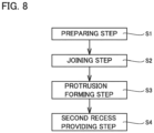
- Fig. 8 is a flowchart illustrating a method of manufacturing ball end mill 200.
- the method of manufacturing ball end mill 200 includes a preparing step S1, a joining step S2, and a protrusion forming step S3.
- the method of manufacturing ball end mill 200 is different from the method of manufacturing ball end mill 100.
- the method of manufacturing ball end mill 200 further includes a second recess providing step S4.
- the method of manufacturing ball end mill 200 is different from the method of manufacturing ball end mill 100.
- second recess 24 is provided.
- metal powder is placed on surface 21 (partial spherical surface 21a).
- Metal for example, iron, cobalt, or nickel
- having a high affinity for diamond is selected as such metal powder.
- surface 21 is heated to cause the above-mentioned metal powder to react with diamonds contained in tip end portion 20. As a result, the diamonds are removed from surface 21 of the portion to which the above-mentioned metal powder adheres, so that each second recess 24 is provided.
- each second recess 24 can be changed by adjusting the grain size of the grains of the above-mentioned metal powder to be placed, and the area ratio of second recesses 24 can be changed by adjusting the amount of the above-mentioned metal powder to be placed.
- the method of providing second recess 24 is not limited to the above-mentioned example.
- Second recess 24 may be provided, for example, by irradiating surface 21 (partial spherical surface 21a) with laser.
- second recess 24 and cutting edge 21c simultaneously act as cutting edges.
- Such a combination of larger and smaller cutting edges provides a cutting effect as if it is achieved in processing by grinding.
- ball end mill 200 can improve the accuracy in processing a workpiece.
- each second recess 24 in a plan view When the equivalent circle diameter of each second recess 24 in a plan view is excessively large, such an excessively large equivalent circle diameter makes it difficult for each second recess 24 to act as a cutting edge. Further, when the equivalent circle diameter of each second recess 24 in a plan view is excessively small, swarf and the like is more likely to get clogged in each second recess 24. Thus, the equivalent circle diameter of each second recess 24 in a plan view is set at 0.5 ⁇ m or more and 50 ⁇ m or less, and thereby, the lifetime of the tool can be further improved.
- the first cutting test was conducted in order to check the influences of the skewness at surface 21, the height (height H) of protrusion 22, the arithmetic mean height in each protrusion 22, the depth (depth D) of second recess 24, the equivalent circle diameter of each second recess 24 in a plan view, and the area ratio of second recesses 24. The following describes this cutting test.
- Samples 1-1 to 1-11 each were used as ball end mill 200.
- the skewness at surface 21, height H, the arithmetic mean height in each protrusion 22, depth D, the equivalent circle diameter of each second recess 24 in a plan view, and the area ratio of second recesses 24 were changed as shown in Table 1.
- diameter R was set at 1.0 mm.
- tip end portion 20 was formed of a nano-polycrystalline diamond.
- the first cutting test was conducted on the conditions of a rotation speed of ball end mill 200 of 30000 rpm, a tool feed rate of 400 mm/min, an amount of cut of 0.005 mm, and a width of cut of 0.002 mm.
- the first cutting test was conducted by dry processing without supplying a coolant.
- the workpiece used in the first cutting test was a cemented carbide AF1 manufactured by Sumitomo Electric Industries, Ltd.
- the lifetime of the tool of each of Samples 1-1 to 1-11 was evaluated based on the cutting distance obtained until the point when the arithmetic mean roughness of the workpiece on the processed surface reached 0.05 ⁇ m or more. Table 2 shows the results of the first cutting test.
- Samples 1-1 to 1-6 each were longer in lifetime of the tool than Sample 1-7.
- the skewness at surface 21 of each of Samples 1-1 to 1-6 was less than 0.
- the skewness at surface 21 of Sample 1-7 was a positive value. The above-mentioned comparison empirically showed that the lifetime of the tool of ball end mill 200 was improved when the skewness at surface 21 was less than 0.
- Samples 1-1 to 1-6 each were longer in lifetime of the tool than Sample 1-8.
- Height H of each of Samples 1-1 to 1-6 fell within the range of 0.05 ⁇ m or more and 20 ⁇ m or less.
- Height H of Sample 1-8 fell outside the range of 0.05 ⁇ m or more and 20 ⁇ m or less.
- the arithmetic mean height in each protrusion 22 of each of Samples 1-1 to 1-6 fell within the range of 0.05 ⁇ m or more and 5 ⁇ m or less.
- the arithmetic mean height in each protrusion 22 of Sample 1-8 fell outside the range of 0.05 ⁇ m or more and 5 ⁇ m or less.
- Samples 1-1 to 1-6 each were longer in lifetime of the tool than Sample 1-9. Depth D of each of Samples 1-1 and 1-6 was 1.0 ⁇ m or more. Depth D of Sample 1-9 was less than 1.0 ⁇ m. The above-mentioned comparison empirically showed that the lifetime of the tool of ball end mill 200 was improved when depth D was 1.0 ⁇ m or more.
- Samples 1-1 to 1-6 each were longer in lifetime of the tool than Sample 1-10.
- the equivalent circle diameter of each second recess 24 of each of Samples 1-1 to 1-6 fell within the range of 0.5 ⁇ m or more and 50 ⁇ m or less.
- the equivalent circle diameter of each second recess 24 of Sample 1-10 fell outside the range of 0.5 ⁇ m or more and 50 ⁇ m or less.
- the above-mentioned comparison empirically showed that the lifetime of the tool of ball end mill 200 was improved when the equivalent circle diameter of each second recess 24 was 0.5 ⁇ m or more and 50 ⁇ m or less.
- Samples 1-1 to 1-6 each were longer in lifetime of the tool than Sample 1-11.
- the area ratio of second recesses 24 in surface 21 of each of Samples 1-1 to 1-6 fell within the range of 3 percent or more and 80 percent or less.
- the area ratio of second recesses 24 in surface 21 of Sample 1-11 fell outside the range of 3 percent or more and 80 percent or less.
- the above-mentioned comparison empirically showed that the lifetime of the tool of ball end mill 200 was improved when the area ratio of second recesses 24 in surface 21 was 3 percent or more and 80 percent or less.
- the second cutting test was conducted in order to check the influences of the skewness at surface 21, the height (height H) of protrusion 22, the arithmetic mean height in each protrusion 22, the depth (depth D) of each second recess 24, the equivalent circle diameter of each second recess 24 in a plan view, and the area ratio of second recesses 24. The following describes this second cutting test.
- Samples 2-1 to 2-11 each were used as ball end mill 200.
- the skewness at surface 21, height H, the arithmetic mean height in each protrusion 22, depth D, the equivalent circle diameter of each second recess 24 in a plan view, and the area ratio of second recesses 24 were changed as shown in Table 3.
- Samples 2-1 to 2-11 each had a diameter R of 3.0 mm.
- tip end portion 20 was formed of a nano-polycrystalline diamond containing atoms belonging to Group 13 or Group 15 in the long periodic table.
- the second cutting test was conducted on the conditions of a rotation speed of ball end mill 200 of 10000 rpm, a tool feed rate of 100 mm/min, an amount of cut of 0.015 mm, and a width of cut of 0.02 mm.
- the second cutting test was conducted while supplying a water-soluble coolant.
- the workpiece used in the second cutting test was quartz glass.
- the lifetime of the tool of each of Samples 2-1 to 2-11 was evaluated based on the cutting distance obtained until the point when the amount of wear on the flank face (partial spherical surface 21a) reached 50 ⁇ m or more. Table 4 shows the results of the second cutting test.
- Samples 2-1 to 2-6 each were longer in lifetime of the tool than Sample 2-7.
- the skewness at surface 21 of each of Samples 2-1 to 2-6 was less than 0.
- the skewness at surface 21 of Sample 2-7 was a positive value. The above-mentioned comparison empirically showed that the lifetime of the tool of ball end mill 200 was improved when the skewness at surface 21 was less than 0.
- Samples 2-1 to 2-6 each were longer in lifetime of the tool than Sample 2-8.
- Height H of each of Samples 2-1 to 2-6 fell within the range of 0.05 ⁇ m or more and 20 ⁇ m or less.
- Height H of Sample 2-8 fell outside the range of 0.05 ⁇ m or more and 20 ⁇ m or less.
- the arithmetic mean height in each protrusion 22 of each of Samples 2-1 to 2-6 fell within the range of 0.05 ⁇ m or more and 5 ⁇ m or less.
- the arithmetic mean height in each protrusion 22 of Sample 2-8 fell outside the range of 0.05 ⁇ m or more and 5 ⁇ m or less.
- Samples 2-1 to 2-6 each were longer in lifetime of the tool than Sample 2-9. Depth D of each of Samples 2-1 to 2-6 was 1.0 ⁇ m or more. Depth D of Sample 2-9 was less than 1.0 ⁇ m. The above-mentioned comparison empirically showed that the lifetime of the tool of ball end mill 200 was improved when depth D was 1.0 ⁇ m or more.
- Samples 2-1 to 2-6 each were longer in lifetime of the tool than Sample 2-10.
- the equivalent circle diameter of each second recess 24 of each of Samples 2-1 to 2-6 fell within the range of 0.5 ⁇ m or more and 50 ⁇ m or less.
- the equivalent circle diameter of each second recess 24 of Sample 2-10 fell outside the range of 0.5 ⁇ m or more and 50 ⁇ m or less.
- the above-mentioned comparison empirically showed that the lifetime of the tool of ball end mill 200 was improved when the equivalent circle diameter of each second recess 24 was 0.5 ⁇ m or more and 50 ⁇ m or less.
- Samples 2-1 to 2-6 each were longer in lifetime of the tool than Sample 2-11.
- the area ratio of second recesses 24 in surface 21 of each of Samples 2-1 to 2-6 fell within the range of 3 percent or more and 80 percent or less.
- the area ratio of second recesses 24 in surface 21 of sample 2-11 fell outside the range of 3 percent or more and 80 percent or less.
- the above-mentioned comparison empirically showed that the lifetime of the tool of ball end mill 200 was improved when the area ratio of second recesses 24 in surface 21 was 3 percent or more and 80 percent or less.
- ball end mill 200A a modification of ball end mill 200
- the following mainly describes the differences from the configuration of ball end mill 200, but the same description will not be repeated.
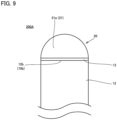
- Fig. 9 is an enlarged side view showing a tip end portion 20 of ball end mill 200A and the vicinity thereof. As shown in Fig. 9 , groove 21b and cutting edge 21c are not provided on a surface 21 of ball end mill 200A. However, as described above, second recess 24 acts as a minute cutting edge. Accordingly, ball end mill 200A can process a workpiece without including cutting edge 21c.
- the tool according to the third embodiment is a cutting tool for cutting a workpiece. More specifically, the tool according to the third embodiment is a cutting insert 300.
- Fig. 10 is a perspective view of cutting insert 300.
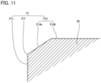
- Fig. 11 is a cross-sectional view of a tip end portion 20 of cutting insert 300. As shown in Figs. 10 and 11 , cutting insert 300 has a base body 30 and a tip end portion 20.
- Base body 30 has a first surface 30a, a second surface 30b, and a side surface 30c. Second surface 30b is located opposite to first surface 30a. Side surface 30c is contiguous to first surface 30a and second surface 30b. Base body 30 has an attachment portion 31. Attachment portion 31 is located at a corner portion of base body 30 when viewed in the direction orthogonal to first surface 30a.
- first surface 30a and second surface 30b located in attachment portion 31 are smaller than the distance between first surface 30a and second surface 30b located at positions other than the position of attachment portion 31.
- attachment portion 31 is provided with a stepped portion on the first surface 30a side of base body 30.
- Base body 30 is formed of a cemented carbide, for example.
- Tip end portion 20 is attached to attachment portion 31 by brazing or the like.
- Surface 21 of tip end portion 20 has a rake face 21d, a flank face 21e, and a cutting edge21f.
- Rake face 21d is contiguous to flank face 21e.
- Rake face 21d is contiguous to first surface 30a on the side opposite to flank face 21e.
- Flank face 21e is contiguous to side surface 30c on the side opposite to rake face 21d.
- Cutting edge 21f is formed along a ridgeline between rake face 21d and flank face 21e.
- Rake face 21d has a first portion 21da and a second portion 21db.
- First portion 21da is a portion of rake face 21d that is contiguous to flank face 21e.
- Second portion 21db is located across first portion 21da from cutting edge 21f.
- First portion 21da is inclined with respect to second portion 21db so as to form a negative angle with respect to second portion 21db.
- the state where first portion 21da forms a negative angle with respect to second portion 21db means the state where first portion 21da is rotated counterclockwise with respect to second portion 21db when second portion 21db faces upward and flank face 21e faces leftward.
- first portion 21da is a negative land.
- Protrusion 22 and first recess 23 are provided in each of rake face 21d and flank face 21e. More specifically, protrusion 22 and first recess 23 are provided in each of first portion 21da and flank face 21e. Rake face 21d (first portion 21da) and flank face 21e may be further provided with second recess 24.
- the following describes a method of manufacturing cutting insert 300.
- Fig. 12 is a flowchart illustrating a method of manufacturing cutting insert 300.
- the method of manufacturing cutting insert 300 includes a preparing step S1, a joining step S2, a face forming step S5, and a protrusion forming step S3.
- the method of manufacturing cutting insert 300 may further include a second recess providing step S4.
- preparing step S1 members constituting base body 30 and tip end portion 20 are prepared. Protrusion 22 and first recess 23 are not provided in surface 21 of tip end portion 20 prepared in preparing step S1.
- joining step S2 base body 30 and tip end portion 20 are joined, for example, by brazing.
- rake face 21d and flank face 21e are formed on surface 21. Rake face 21d and flank face 21e each are formed, for example, by irradiating surface 21 with laser. In face forming step S5, formation of rake face 21d and flank face 21e also leads to formation of cutting edge 21f. Since protrusion forming step S3 and second recess providing step S4 are as described above, the description thereof will not be repeated.
- cutting insert 300 when the workpiece is processed by cutting insert 300, not only cutting edge 21f cuts the workpiece, but also second recess 24 provided in flank face 21e acts as a minute cutting edge to grind the workpiece, and therefore, the processing quality of the workpiece surface (the surface roughness of the workpiece surface) is improved. In this way, cutting insert 300 can improve the accuracy in processing the workpiece.
- a cutting test was conducted in order to check the influences of the skewness at surface 21, the height (height H) of protrusion 22, the arithmetic mean height in each protrusion 22, the depth (depth D) of second recess 24, the equivalent circle diameter of each second recess 24 in a plan view, and the area ratio of second recesses 24. The following describes this cutting test.
- Samples 3-1 to 3-11 each were used as cutting insert 300.
- the skewness at surface 21, height H, the arithmetic mean height in each protrusion 22, depth D, the equivalent circle diameter of each second recess 24 in a plan view, and the area ratio of second recesses 24 were changed as shown in Table 5.
- tip end portion 20 was formed of binderless cubic boron nitride.
- Samples 3-1 to 3-6 each were longer in lifetime of the tool than Sample 3-7.
- the skewness at surface 21 of each of Samples 3-1 to 3-6 was less than 0.
- the skewness at surface 21 of Sample 3-7 was a positive value. The above-mentioned comparison empirically showed that the lifetime of the tool of cutting insert 300 was improved when the skewness at surface 21 was less than 0.
- Samples 3-1 to 3-6 each were longer in lifetime of the tool than Sample 3-8.
- Height H of each of Samples 3-1 to 3-6 fell within the range of 0.05 ⁇ m or more and 20 ⁇ m or less.
- Height H of Sample 3-8 fell outside the range of 0.05 ⁇ m or more and 20 ⁇ m or less.
- the arithmetic mean height in each protrusion 22 of each of Samples 3-1 to 3-6 fell within the range of 0.05 ⁇ m or more and 5 ⁇ m or less.
- the arithmetic mean height in each protrusion 22 of Sample 3-8 fell outside the range of 0.05 ⁇ m or more and 5 ⁇ m or less.
- Samples 3-1 to 3-6 each were longer in lifetime of the tool than Sample 3-9.
- Depth D of each of Samples 3-1 to 3-6 was 1.0 ⁇ m or more.
- Depth D of Sample 3-9 was less than 1.0 ⁇ m. The above-mentioned comparison empirically showed that the lifetime of the tool of cutting insert 300 was improved when depth D was 1.0 ⁇ m or more.
- Samples 3-1 to 3-6 each were longer in lifetime of the tool than Sample 3-10.
- the equivalent circle diameter of each second recess 24 of each of Samples 3-1 to 3-6 fell within the range of 0.5 ⁇ m or more and 50 ⁇ m or less.
- the equivalent circle diameter of each second recess 24 of Sample 3-10 fell outside the range of 0.5 ⁇ m or more and 50 ⁇ m or less.
- the above-mentioned comparison empirically showed that the lifetime of the tool of cutting insert 300 was improved when the equivalent circle diameter of each second recess 24 was 0.5 ⁇ m or more and 50 ⁇ m or less.
- Samples 3-1 to 3-6 each were longer in lifetime of the tool than Sample 3-11.
- the area ratio of second recesses 24 in surface 21 of each of Samples 3-1 to 3-6 fell within the range of 3 percent or more and 80 percent or less.
- the area ratio of second recesses 24 in surface 21 of Sample 3-11 fell outside the range of 3 percent or more and 80 percent or less.
- the above-mentioned comparison empirically showed that the lifetime of the tool of cutting insert 300 was improved when the area ratio of second recesses 24 in surface 21 was 3 percent or more and 80 percent or less.
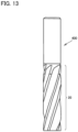
- Fig. 13 is a side view of a radius end mill 400.
- the details of the above-described third embodiment are applicable, for example, to radius end mill 400 as shown in Fig. 13 . More specifically, protrusion 22 and first recess 23 are provided in each of the flank face and the rake face formed on tip end portion 20 of radius end mill 400.
- the tool according to the fourth embodiment is a measurement tool for measuring the surface roughness or the shape of a workpiece. More specifically, the tool according to the fourth embodiment is a stylus 500.
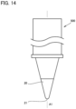
- Fig. 14 is a side view of stylus 500.
- stylus 500 has a tip end portion 20.
- Stylus 500 scans over a workpiece such that a surface 21 of stylus 500 comes into contact with the surface of the workpiece. Thereby, the surface roughness or the shape of the workpiece is measured.
- Surface 21 is provided with a protrusion 22 and a first recess 23.
- Surface 21 may further be provided with a second recess 24. It is assumed that a central axis A1 represents the central axis of stylus 500.
- the tool according to the fifth embodiment is a ball end mill 600.
- the following mainly describes the differences from the configuration of ball end mill 200, but the same description will not be repeated.
- Fig. 15 is a schematic plan view of a partial spherical surface 21a of ball end mill 600.
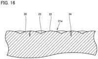
- Fig. 16 is a cross-sectional view taken along a line XVI-XVI in Fig. 15 .
- each second recess 24 has an elongated shape in a plan view. More specifically, in ball end mill 600, the length of second recess 24 in its longitudinal direction is greater than the width of second recess 24 in its width direction. The width direction of second recess 24 is orthogonal to the longitudinal direction of second recess 24.
- second recess 24 in its longitudinal direction is 2 ⁇ depth D ⁇ sin ⁇ (an angle ⁇ will be described later) or more.
- second recess 24 is provided inside protrusion 22 or provided to extend across two adjacent protrusions 22.
- a length L represents the length of second recess 24 in its longitudinal direction in a plan view. Length L is preferably 100 ⁇ m or less.
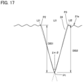
- a depth D (see Fig. 17 ) representing the depth of second recess 24 is preferably 0.5 ⁇ m or more and 20 ⁇ m or less.
- an angle ⁇ (see Fig. 17 ) represents the inclination angle of the side surface of second recess 24. Angle ⁇ is preferably more than 0° and equal to or less than 45°.
- the area ratio of second recesses 24 is preferably 3 percent or more and 80 percent or less.
- Depth D, angle ⁇ , and length L are measured by the following method.
- a contactless surface shape measuring apparatus Infinite Focus G5 manufactured by Bruker Alicona
- the profile curve of the measurement target portion in a cross section of second recess 24 orthogonal to its longitudinal direction is calculated. It is assumed that the measurement length of the profile curve is 50 ⁇ m or more.
- the inclination, waviness, and the like of the profile curve are corrected according to JIS B 0651:2001.
- the measurement target portion has a circular shape, this measurement target portion is converted to be shown in a Cartesian circle.
- the profile curve is calculated at 50 or more positions at intervals of 2 ⁇ m in the longitudinal direction of each second recess 24.
- positions P1, P2, and P3 are specified from the calculated profile curve of the measurement target portion along one cross section of second recess 24 orthogonal to its longitudinal direction.
- the profile curve shows a minimum value.
- the profile curve shows a maximum value.
- Positions P2 and P3 are located closest to position P1 among the positions where the above-mentioned profile curve shows the maximum value.
- Fig. 17 is a schematic profile curve of a measurement target portion along a cross section of second recess 24 orthogonal to its longitudinal direction.
- a straight line LI1 is assumed to connect positions P1 and P2 while a straight line LI2 is assumed to connect positions P1 and P3.
- Angle ⁇ is 0.5 times as large as the angle formed by straight lines LI1 and LI2.
- Depth D represents an average value of: a distance DIS1 as a difference in height between positions P2 and P1; and a distance DIS2 as a difference in height between positions P3 and P2. The above-described measurement is made for other cross sections to thereby obtain depth D for each cross section.
- a depth D avg represents the average value of depths D of the respective cross sections.
- Length L represents the maximum value of the distance between the cross section along which depth D falls within the range of ⁇ 20 percent of depth D avg and the cross section along which position P1 falls within the range of ⁇ 2 ⁇ D ⁇ sin ⁇ . Note that length L may be measured from the observation view on the surface when length L can be clearly observed from the view on the surface.
- the area of second recess 24 can be regarded as 2 ⁇ depth D ⁇ sin ⁇ ⁇ length L.
- the area ratio of second recesses 24 can be obtained by dividing the total area of second recesses 24 calculated based on this expression by the area of surface 21 provided with protrusions 22 and first recesses 23.
- each second recess 24 preferably extends in the circumferential direction around a rotation axis A.
- the longitudinal direction of each second recess 24 is preferably orthogonal to the circumferential direction around rotation axis A. Note that rotation axis A passes through the center of partial spherical surface 21a.
- the following describes a method of manufacturing ball end mill 600.
- the method of manufacturing ball end mill 600 includes a preparing step S1, a joining step S2, a protrusion forming step S3, and a second recess providing step S4.
- second recess 24 is provided by irradiating partial spherical surface 21a with laser in second recess providing step S4.
- the processing conditions of the above-mentioned laser processing are changed to appropriately adjust depth D, angle ⁇ , and length L.
- the coolant flowing through each second recess 24 or air flowing during rotation of ball end mill 600 readily flows into a contact portion that contacts the workpiece, so that the cooling effect is enhanced and the lifetime of the tool is improved.
- the wear debris powder produced due to contact with the workpiece is readily discharged through each second recess 24 from the contact portion that contacts the workpiece, so that secondary wear resulting from such wear debris powder is less likely to occur, and thus, the lifetime of the tool is improved.
- each second recess 24 When length L is equal to or greater than 2 ⁇ depth D ⁇ sin ⁇ and equal to or less than 100 ⁇ m, such length L facilitates functioning of each second recess 24 as a path through which a coolant or the like flows and a path through which wear debris powder is discharged. Thus, the lifetime of the tool can be further improved. Further, when angle ⁇ is more than 0° and equal to or less than 45°, the side surface of each second recess 24 is steeply inclined, so that the flow velocity of the coolant or the like is more likely to rise when the coolant or the like passes through each second recess 24. Thus, in this case, the cooling effect can be further enhanced, and the lifetime of the tool is further improved.
- a cutting test was conducted in order to check the effect of ball end mill 600.
- Samples 4-1 to 4-11 each were used as a sample of ball end mill 600.
- the cutting test was conducted on the conditions of a rotation speed of ball end mill 600 of 10000 rpm, a tool feed rate of 100 mm/min, an amount of cut of 0.015 mm, and a width of cut of 0.02 mm.
- the cutting test was conducted while supplying a water-soluble coolant.
- the workpiece used in the cutting test was a plate of quartz glass of 10 mm ⁇ 10 mm.
- the lifetime of the tool of each sample was evaluated based on the cutting distance obtained until the point when wearing away of the flank face reached 50 ⁇ m.
- tip end portion 20 was formed of a nano-polycrystalline diamond.
- depth D, angle ⁇ , length L, the area ratio of second recesses 24, and whether boron was added or not were changed as shown in Table 7.
- a condition A defines that depth D is 0.5 ⁇ m or more and 20 ⁇ m or less.
- a condition B defines that angle ⁇ is more than 0° and equal to or less than 45°.
- a condition C defines that length L is equal to or more than 2 ⁇ depth D ⁇ sin ⁇ and equal to or less than 100 ⁇ m. As described above, 2 ⁇ depth D ⁇ sin ⁇ corresponds to the width of each second recess 24.
- a condition D defines that the area ratio of second recesses 24 is 3 percent or more and 80 percent or less.
- each second recess 24 was provided such that its width direction extended in the circumferential direction around rotation axis A.
- the skewness at surface 21 was less than 0, height H fell within the range of 0.05 ⁇ m or more and 20 ⁇ m or less, and the arithmetic mean height at surface 21 fell within the range of 0.05 ⁇ m or more and 5 ⁇ m or less.
- the tool according to the sixth embodiment is a cutting insert 700.
- the following mainly describes the differences from the configuration of cutting insert 300, but the same description will not be repeated.
- each second recess 24 is provided in at least one of rake face 21d and flank face 21e.
- the width direction of each second recess 24 extends in the direction in which cutting edge 21f extends. According to cutting insert 700, the lifetime of the tool is improved as in ball end mill 600.
- the tool according to the seventh embodiment is a stylus 800.
- the following mainly describes the differences from the configuration of stylus 500, but the same description will not be repeated.
- stylus 800 surface 21 is provided with second recesses 24 similar to those in ball end mill 600.
- the width direction of each second recess 24 extends in the circumferential direction around central axis A1. According to stylus 800, wear debris powder produced due to contact with the workpiece is readily discharged from the contact portion through each second recess 24, and thus, secondary wear resulting from the wear debris powder is less likely to occur, so that the lifetime of the tool is improved.
Landscapes
- Engineering & Computer Science (AREA)
- Mechanical Engineering (AREA)
- Physics & Mathematics (AREA)
- Optics & Photonics (AREA)
- Plasma & Fusion (AREA)
- Milling Processes (AREA)
- Cutting Tools, Boring Holders, And Turrets (AREA)
- Laser Beam Processing (AREA)
- A Measuring Device Byusing Mechanical Method (AREA)
Applications Claiming Priority (4)
| Application Number | Priority Date | Filing Date | Title |
|---|---|---|---|
| JP2020024465 | 2020-06-22 | ||
| JP2020024463 | 2020-06-22 | ||
| JP2020024464 | 2020-06-22 | ||
| PCT/JP2021/022524 WO2021261316A1 (fr) | 2020-06-22 | 2021-06-14 | Outil et procédé de production d'outil |
Publications (2)
| Publication Number | Publication Date |
|---|---|
| EP4169643A1 true EP4169643A1 (fr) | 2023-04-26 |
| EP4169643A4 EP4169643A4 (fr) | 2023-12-20 |
Family
ID=79281186
Family Applications (1)
| Application Number | Title | Priority Date | Filing Date |
|---|---|---|---|
| EP21829115.1A Pending EP4169643A4 (fr) | 2020-06-22 | 2021-06-14 | Outil et procédé de production d'outil |
Country Status (7)
| Country | Link |
|---|---|
| US (1) | US12678869B2 (fr) |
| EP (1) | EP4169643A4 (fr) |
| JP (1) | JP7362925B2 (fr) |
| KR (1) | KR20230026976A (fr) |
| CN (1) | CN114450123B (fr) |
| TW (1) | TWI915380B (fr) |
| WO (1) | WO2021261316A1 (fr) |
Families Citing this family (3)
| Publication number | Priority date | Publication date | Assignee | Title |
|---|---|---|---|---|
| WO2021106075A1 (fr) * | 2019-11-26 | 2021-06-03 | 住友電気工業株式会社 | Outil de mesure ayant une partie pointe en diamant polycristallin |
| USD991993S1 (en) | 2020-06-24 | 2023-07-11 | Sumitomo Electric Hardmetal Corp. | Cutting tool |
| JP7903759B1 (ja) | 2025-05-28 | 2026-08-12 | 住友電工ハードメタル株式会社 | 切削工具 |
Family Cites Families (24)
| Publication number | Priority date | Publication date | Assignee | Title |
|---|---|---|---|---|
| US20030019106A1 (en) * | 2001-04-22 | 2003-01-30 | Diamicron, Inc. | Methods for making bearings, races and components thereof having diamond and other superhard surfaces |
| US7758653B2 (en) * | 2002-05-23 | 2010-07-20 | Active Implants Corporation | Implants |
| US7017465B2 (en) * | 2002-07-29 | 2006-03-28 | L.S. Starrett Company | Cutting tool with grooved cutting edge |
| SE527613C2 (sv) | 2004-10-15 | 2006-04-25 | Seco Tools Ab | Verktyg för skärande bearbetning med en underläggsplatta med urtagningar |
| JP2006255814A (ja) | 2005-03-16 | 2006-09-28 | Micro Diamond Corp | マイクロ回転工具 |
| JP2007313636A (ja) | 2006-04-27 | 2007-12-06 | Kyocera Corp | 切削工具およびそれを用いた被削材の切削方法 |
| US7476064B2 (en) * | 2006-04-27 | 2009-01-13 | Kyocera Corporation | Cutting tool and method of cutting workpiece |
| US20090032725A1 (en) * | 2007-07-30 | 2009-02-05 | Tokyo Electron Limited | Apparatus and methods for treating a workpiece using a gas cluster ion beam |
| WO2010013319A1 (fr) * | 2008-07-30 | 2010-02-04 | オーエスジー株式会社 | Procédé de coupe pour rainure en forme d'arbre et outil de coupe rotatif |
| CN103237620B (zh) * | 2010-12-25 | 2015-09-30 | 京瓷株式会社 | 切削工具及使用了该切削工具的切削加工物的制造方法 |
| JP5468100B2 (ja) | 2012-03-26 | 2014-04-09 | オグラ宝石精機工業株式会社 | スタイラス |
| JP5567622B2 (ja) * | 2012-06-28 | 2014-08-06 | オグラ宝石精機工業株式会社 | スタイラス |
| JP5683640B2 (ja) * | 2013-05-20 | 2015-03-11 | 日本航空電子工業株式会社 | 刃物工具 |
| DE102013018899A1 (de) * | 2013-11-11 | 2015-05-13 | Karlheinz Hahn | Rollierwerkzeug |
| JP5969106B1 (ja) | 2015-12-28 | 2016-08-10 | 日進工具株式会社 | エンドミルとその製造方法 |
| DE112017002152B4 (de) | 2016-04-25 | 2025-10-16 | Kyocera Corporation | Schneidwerkzeug |
| CN109982812A (zh) * | 2016-11-16 | 2019-07-05 | 住友电工硬质合金株式会社 | 通过使用包含纳米多晶金刚石或气相合成单晶金刚石的金刚石工具对工件进行加工的方法、机床和制造构件的方法 |
| WO2018116524A1 (fr) * | 2016-12-20 | 2018-06-28 | 住友電工ハードメタル株式会社 | Outil de coupe et son procédé de fabrication |
| JP6863076B2 (ja) | 2017-05-24 | 2021-04-21 | 住友電気工業株式会社 | 多結晶ダイヤモンドおよびその製造方法、スクライブツール、スクライブホイール、ドレッサー、回転工具、伸線ダイス、切削工具、電極ならびに多結晶ダイヤモンドを用いた加工方法 |
| JP6863092B2 (ja) | 2017-06-01 | 2021-04-21 | 住友電気工業株式会社 | 多結晶ダイヤモンドおよびその製造方法、スクライブツール、スクライブホイール、ドレッサー、回転工具、ウォータージェット用オリフィス、伸線ダイス、切削工具、電極ならびに多結晶ダイヤモンドを用いた加工方法 |
| DE102017112827B4 (de) * | 2017-06-12 | 2022-08-11 | Kohnle GmbH | Fräswerkzeug zur Bearbeitung von faserverstärkten Werkstoffen |
| JP7006881B2 (ja) | 2017-08-22 | 2022-01-24 | 住友電工ハードメタル株式会社 | 切削工具およびその製造方法 |
| US10710174B2 (en) | 2017-11-30 | 2020-07-14 | Iscar, Ltd. | Slitting cutter and tool key in combination therewith |
| JP7516714B2 (ja) | 2018-10-30 | 2024-07-17 | 兼房株式会社 | 回転工具 |
-
2021
- 2021-06-14 WO PCT/JP2021/022524 patent/WO2021261316A1/fr not_active Ceased
- 2021-06-14 KR KR1020227010106A patent/KR20230026976A/ko active Pending
- 2021-06-14 EP EP21829115.1A patent/EP4169643A4/fr active Pending
- 2021-06-14 CN CN202180005574.6A patent/CN114450123B/zh active Active
- 2021-06-14 US US17/763,431 patent/US12678869B2/en active Active
- 2021-06-14 JP JP2022531807A patent/JP7362925B2/ja active Active
- 2021-06-21 TW TW110122518A patent/TWI915380B/zh active
Also Published As
| Publication number | Publication date |
|---|---|
| TW202204069A (zh) | 2022-02-01 |
| EP4169643A4 (fr) | 2023-12-20 |
| CN114450123A (zh) | 2022-05-06 |
| CN114450123B (zh) | 2024-09-17 |
| US20220339719A1 (en) | 2022-10-27 |
| WO2021261316A1 (fr) | 2021-12-30 |
| US12678869B2 (en) | 2026-07-14 |
| KR20230026976A (ko) | 2023-02-27 |
| TWI915380B (zh) | 2026-02-21 |
| JP7362925B2 (ja) | 2023-10-17 |
| JPWO2021261316A1 (fr) | 2021-12-30 |
Similar Documents
| Publication | Publication Date | Title |
|---|---|---|
| KR102214373B1 (ko) | 절삭 인서트 | |
| CN100562388C (zh) | 加工用cbn切削工具及其车削加工方法 | |
| US6652201B2 (en) | Ball end mill | |
| CA2567077C (fr) | Outil de coupe pour usinage de grande qualite a grande efficacite et methode de coupe connexe | |
| US20070172321A1 (en) | Ball endmill | |
| JP6191839B2 (ja) | ダイヤモンド焼結体ボールエンドミルとその製造方法 | |
| TWI436840B (zh) | Ball cutter | |
| US20220339719A1 (en) | Tool and method of manufacturing tool | |
| CN106113293B (zh) | 划线轮及其制造方法 | |
| EP4088845B1 (fr) | Fraise à embout sphérique | |
| JP5814611B2 (ja) | エンドミル | |
| CN118513597A (zh) | 铣刀、加工设备及铣刀制造方法 | |
| JP2001212703A (ja) | 多結晶硬質焼結体切削工具 | |
| JP3477183B2 (ja) | ダイヤモンド被覆切削工具 | |
| CN112355333A (zh) | 一种刀具及其刀头结构 | |
| JP2003175408A (ja) | 多結晶硬質焼結体スローアウェイチップ | |
| JP3485544B2 (ja) | フライス工具 | |
| JP2013013962A (ja) | Cbnエンドミル | |
| WO2021260778A1 (fr) | Outil, et procédé de fabrication de celui-ci | |
| CN115702053B (zh) | 切削工具 | |
| WO2021260777A1 (fr) | Outil, et procédé de fabrication de celui-ci | |
| WO2021260776A1 (fr) | Outil, et procédé de fabrication de celui-ci | |
| JP3657546B2 (ja) | ドリル | |
| CN217453549U (zh) | 一种硬质合金与高速钢磨削用钎焊金刚石磨轮 | |
| JP5873345B2 (ja) | エンドミル |
Legal Events
| Date | Code | Title | Description |
|---|---|---|---|
| STAA | Information on the status of an ep patent application or granted ep patent |
Free format text: STATUS: THE INTERNATIONAL PUBLICATION HAS BEEN MADE |
|
| PUAI | Public reference made under article 153(3) epc to a published international application that has entered the european phase |
Free format text: ORIGINAL CODE: 0009012 |
|
| STAA | Information on the status of an ep patent application or granted ep patent |
Free format text: STATUS: REQUEST FOR EXAMINATION WAS MADE |
|
| 17P | Request for examination filed |
Effective date: 20220329 |
|
| AK | Designated contracting states |
Kind code of ref document: A1 Designated state(s): AL AT BE BG CH CY CZ DE DK EE ES FI FR GB GR HR HU IE IS IT LI LT LU LV MC MK MT NL NO PL PT RO RS SE SI SK SM TR |
|
| DAV | Request for validation of the european patent (deleted) | ||
| DAX | Request for extension of the european patent (deleted) | ||
| A4 | Supplementary search report drawn up and despatched |
Effective date: 20231117 |
|
| RIC1 | Information provided on ipc code assigned before grant |
Ipc: C30B 33/08 20060101ALI20231113BHEP Ipc: G01B 5/012 20060101ALI20231113BHEP Ipc: B23K 103/00 20060101ALI20231113BHEP Ipc: B23K 101/20 20060101ALI20231113BHEP Ipc: B23K 26/402 20140101ALI20231113BHEP Ipc: B23K 26/364 20140101ALI20231113BHEP Ipc: B23K 26/362 20140101ALI20231113BHEP Ipc: B23P 15/34 20060101ALI20231113BHEP Ipc: B23C 5/10 20060101ALI20231113BHEP Ipc: B23B 27/20 20060101ALI20231113BHEP Ipc: B23B 27/14 20060101AFI20231113BHEP |