EP4169671A1 - Sicherheitssystem und verfahren zum lehren eines roboters - Google Patents
Sicherheitssystem und verfahren zum lehren eines roboters Download PDFInfo
- Publication number
- EP4169671A1 EP4169671A1 EP21204402.8A EP21204402A EP4169671A1 EP 4169671 A1 EP4169671 A1 EP 4169671A1 EP 21204402 A EP21204402 A EP 21204402A EP 4169671 A1 EP4169671 A1 EP 4169671A1
- Authority
- EP
- European Patent Office
- Prior art keywords
- robot
- mode
- safety
- hand
- guiding
- Prior art date
- Legal status (The legal status is an assumption and is not a legal conclusion. Google has not performed a legal analysis and makes no representation as to the accuracy of the status listed.)
- Withdrawn
Links
Images


Classifications
-
- B—PERFORMING OPERATIONS; TRANSPORTING
- B25—HAND TOOLS; PORTABLE POWER-DRIVEN TOOLS; MANIPULATORS
- B25J—MANIPULATORS; CHAMBERS PROVIDED WITH MANIPULATION DEVICES
- B25J9/00—Program-controlled manipulators
- B25J9/16—Program controls
- B25J9/1656—Program controls characterised by programming, planning systems for manipulators
-
- B—PERFORMING OPERATIONS; TRANSPORTING
- B25—HAND TOOLS; PORTABLE POWER-DRIVEN TOOLS; MANIPULATORS
- B25J—MANIPULATORS; CHAMBERS PROVIDED WITH MANIPULATION DEVICES
- B25J9/00—Program-controlled manipulators
- B25J9/16—Program controls
- B25J9/1674—Program controls characterised by safety, monitoring, diagnostic
-
- G—PHYSICS
- G05—CONTROLLING; REGULATING
- G05B—CONTROL OR REGULATING SYSTEMS IN GENERAL; FUNCTIONAL ELEMENTS OF SUCH SYSTEMS; MONITORING OR TESTING ARRANGEMENTS FOR SUCH SYSTEMS OR ELEMENTS
- G05B19/00—Program-control systems
- G05B19/02—Program-control systems electric
- G05B19/42—Recording and playback systems, i.e. in which the program is recorded from a cycle of operations, e.g. the cycle of operations being manually controlled, after which this record is played back on the same machine
- G05B19/423—Teaching successive positions by walk-through, i.e. the tool head or end effector being grasped and guided directly, with or without servo-assistance, to follow a path
-
- G—PHYSICS
- G05—CONTROLLING; REGULATING
- G05B—CONTROL OR REGULATING SYSTEMS IN GENERAL; FUNCTIONAL ELEMENTS OF SUCH SYSTEMS; MONITORING OR TESTING ARRANGEMENTS FOR SUCH SYSTEMS OR ELEMENTS
- G05B2219/00—Program-control systems
- G05B2219/30—Nc systems
- G05B2219/35—Nc in input of data, input till input file format
- G05B2219/35468—Select between teaching, regulate position and direct control of position
-
- G—PHYSICS
- G05—CONTROLLING; REGULATING
- G05B—CONTROL OR REGULATING SYSTEMS IN GENERAL; FUNCTIONAL ELEMENTS OF SUCH SYSTEMS; MONITORING OR TESTING ARRANGEMENTS FOR SUCH SYSTEMS OR ELEMENTS
- G05B2219/00—Program-control systems
- G05B2219/30—Nc systems
- G05B2219/35—Nc in input of data, input till input file format
- G05B2219/35471—Select between run and step command mode, step forward, reverse
-
- G—PHYSICS
- G05—CONTROLLING; REGULATING
- G05B—CONTROL OR REGULATING SYSTEMS IN GENERAL; FUNCTIONAL ELEMENTS OF SUCH SYSTEMS; MONITORING OR TESTING ARRANGEMENTS FOR SUCH SYSTEMS OR ELEMENTS
- G05B2219/00—Program-control systems
- G05B2219/30—Nc systems
- G05B2219/35—Nc in input of data, input till input file format
- G05B2219/35472—Mode selection
-
- G—PHYSICS
- G05—CONTROLLING; REGULATING
- G05B—CONTROL OR REGULATING SYSTEMS IN GENERAL; FUNCTIONAL ELEMENTS OF SUCH SYSTEMS; MONITORING OR TESTING ARRANGEMENTS FOR SUCH SYSTEMS OR ELEMENTS
- G05B2219/00—Program-control systems
- G05B2219/30—Nc systems
- G05B2219/39—Robotics, robotics to robotics hand
- G05B2219/39447—Dead man switch
Definitions
- the present invention relates to a safety system of a robot and a method thereof, and in particular, to a safety system and a method thereof for protecting a user during teaching a robot when switched from an auto mode to a hand-guiding mode or a non-hand-guiding mode.
- the present disclosure aims at providing a safety system for teaching a robot and a safety method of teaching a robot. This is achieved by the safety system according to claim 1 and the safety method according to claim 9.
- the dependent claims pertain to corresponding further developments and improvements.
- the embodiments of the invention provide a safety system for teaching a robot.
- the safety system switches between various operation modes of the robot via a mode switching device and employs an enabling device to enable different preset safety modules and safety functions corresponding to each teaching mode, to achieve simple switching between multiple operation modes.
- the embodiments of the invention provide a safety method for teaching a robot.
- the method includes utilizing preset safety modules and preset safety functions corresponding to each operation mode to switch the robot and construct a safety system suitable for each operation mode, to ensure the safety of users.
- the embodiments of the invention provide another safety method for teaching a robot.
- the method includes when an operation mode is switched from various operation modes to a hand-guiding mode, maintaining safety modules and safety functions dedicated to the hand-guiding mode, to enhance the safety of users.
- the safety system for teaching the robot includes the robot having a plurality of segments and a movable end, each segment being provided with an actuator and a position sensor coupled to a controller, the controller being configured to control the actuator and the position sensor of the segment, and move the end of the robot.
- the safety system further includes an enabling device coupled to the controller, a safety module provided in the controller, electrically or communicatively coupled to the enabling device, and configured to transmit an electrical signal or a communication signal according to a state of the enabling device, an OFF state of the enabling device setting the robot into a safe state, and an ON state of the enabling device aborting the safe state of the robot, a safety function unit provided in the controller, electrically or communicatively coupled to the safety module, and configured to set the robot into the safe state upon detecting that a safety function of the robot exceeds a predetermined limit, a mode switching device, electrically or communicatively coupled to the controller, the safety module and the safety function unit, and configured to switch an operation mode of the robot.
- the mode switching device switches between operation modes of the robot, the operation modes comprise a hand-guiding mode, an auto mode, a manual reduced speed mode, and a manual high speed mode.
- the safety module and the safety function unit enable preset safety modules and preset safety functions corresponding to each operation mode.
- the safety module is electrically or communicatively coupled to the position sensor of each segment of the robot and receives signals from the respective position sensors to monitor the robot.
- the safety module operates in at least one of the following safe state types: a type 0 safe state providing a power-off shutdown function, in which power to an actuator is shut off when entering the safe state, a type 1 safe state providing an advanced power-off shutdown function, in which the power to the actuator is shut off after the robot completes a speed reduction operation in a (fixed) period of time upon the controller receiving a speed reduction command in the safe state, and a type 2 safe state providing a non-power-off shutdown function, in which standstill monitoring is enabled to continuously monitor the position sensor upon the controller receiving a speed reduction command in the safe state and the robot completing a speed reduction operation in the safe state, and the power to the actuator is shut off upon detecting a movement of the robot.
- the safety function unit enables at least one of the following safety functions: limiting an angle of movements of the segments, limiting
- the mode switching device of the safety system for teaching the robot may switch between operation modes including a teaching mode and an auto mode, the teaching mode including a hand-guiding mode, a manual reduced speed mode, and a manual high speed mode.
- the mode switching device may be provided in the teaching device of the robot, or external to the controller.
- the mode switching device may be a multi-position rotary switch, and the mode may be indicated by a position of the rotary switch, or displayed by a light signal.
- the mode switching device may be a software switch, a combination of hardware switches, or a combination of software and hardware switches.
- the safety method for teaching the robot further includes presetting enablement states and limit parameters of the safety modules and the safety functions according to requirements of each operation mode of the robot.
- the safety method for teaching the robot further includes switching the mode, determining whether the switched mode is the teaching mode such as the manual reduced speed mode or the manual high speed mode, enabling a preset safety function corresponding to the manual reduced speed mode or the manual high speed mode, suspending the robot and setting the same to a safe state, enabling the enabling device, detecting an ON state of the enabling device, quitting the safe state of the robot, and performing a teaching operation on the robot.
- the safety method for teaching the robot further includes if the robot has completed the operation, then terminating the operation, and if the robot has not completed the operation, returning to the switched mode to continue the operation.
- the safety method for teaching the robot further includes if the switched mode is an auto mode, activating a preset safety function corresponding to the auto mode, monitoring the robot, and performing an automatic operation of the robot. In some embodiments, the safety method for teaching the robot further includes if the switched mode is a hand-guiding mode, pressing the enabling device continuously to exit the safe state and enabling the hand-guiding function.
- the safety method for teaching the robot further includes if the mode is switched from the manual reduced speed mode, the manual high speed mode, or the auto mode to the hand-guiding mode, the robot recording a breakpoint of an operation program, and activating a preset safety module and a preset safety function of the hand-guiding mode, upon completion of manual the robot for teaching an operation, switching back to a previous operation mode and proceeding the operation program from the breakpoint.
- a hand-guiding button 2 is set at an end of the robot 1.
- the hand-guiding button 2 is usually designed as a hold-to-run button or a software switch.
- the hand-guiding button 2 is electrically or communicatively coupled to the controller 3 of the robot 1.
- the teaching device 4 sets the robot 1 to a teaching mode, if a user presses the hand-guiding button 2, the controller 3 will be set off by a signal to switch the robot 1 from a static state to a hand-guiding mode.
- the hand-guiding mode has been implemented in several ways in the related art.
- an encoder and a motor current sensor of an actuator in each segment 5 of the robot 1 perform calculations and compensations to determine a force applied to each joint or a hand-guiding force applied to the end, thereby controlling the robot 1 to follow a hand-guiding operation.
- the robot 1 is taught about how to operate by hand-guiding the robot 1 to recorded positions or by recording a path of hand-guiding.
- the hand-guiding button 2 is released, the robot 1 is exited from the hand-guiding mode and returns to a static state.
- a teaching device 4 of the robot 1 in the related art is equipped with an enabling device in the teaching mode to protect the operator.
- the enabling device 6 is usually located on the teaching device 4 and is a three-position switch including 3 pressing stages, namely a fully released position, an intermediate position, and a pressed position, of which only the intermediate position may enable the robot 1 to perform the teaching operation.
- a safety system 7 interrupts the teaching operation to stop the robot 1 from moving and keep the robot 1 not acting rashly via standstill monitoring when the actuator is still powered. If it is found that the robot is moving, the safety system 7 will cut off the power to the actuator of the robot 1 to ensure the safety of the operator during the teaching operation.
- robots need to be hand-guided to work, work collaboratively or perform a variety of teaching tasks such as crawling, trial operation, and other non-hand-guiding tasks.
- teaching tasks need to meet different safety requirements.
- a hand-guiding operation is used in auto mode. Applying a single operation of a safety system to all teaching operations may result in severe injuries to users. Therefore, a safety system and a method of hand-guiding a robot are in need.
- a robot is configured to operate in the following operation modes: an auto mode, and a manual mode (or a teaching mode).
- the teaching mode comprises a manual reduced speed mode and a manual high speed mode.
- the robot In the auto mode, the robot automatically runs a program.
- the auto mode is used in production automation operations, and the user is a production line operator.
- the manual or teaching mode is not used in the production automation operation, and is used for the programming and testing a robot program, and the user is an automation engineer.
- the manual reduced speed mode is used for guiding to a specific point, programming, and low-speed trial operations, while the manual high speed mode is only used for program trial operations, achieving a full speed trial operation of the program, similar to the auto mode but requiring additional safety protection device, such as pressing an enable device on a teaching device to ensure safety.
- a common mode switching device such as a three-position rotary switch is used to switch between conventional operation modes such as an auto mode (AUT), a manual reduced speed mode (T1), and a manual high speed mode (T2).
- a hand-guiding function is only defined as a collaborative function in ISO 10218-1, but it is not clearly stated what purpose it is used for.
- hand-guiding has been used in a variety of operation modes, typically used in the manual mode or the teach mode to assist an automation engineer in teaching locations or hand-guiding a path, and also used in the auto mode to facilitate production line operators to perform the following tasks: a guided movement (e.g., hand-guiding the robot to the next starting point of an operation), a guided demonstration (e.g., hand-guiding an operation path), a hand-guided cooperation (e.g., the robot lifts a weight and a user guides the robot to a placement position), the hand-guided operations in the auto mode are not the teaching behavior specified in the safety standard, but hand-guided operations in an automatic production process. Therefore, hand-guiding has been widely used in the auto mode and the manual or teaching mode.
- a guided movement e.g., hand-guiding the robot to the next starting point of an operation
- a guided demonstration e.g., hand-guiding an operation path
- a hand-guided cooperation e.g., the robot lifts a weight and a user
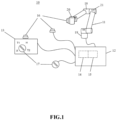
- FIG. 1 is a schematic diagram of a safety system for teaching a robot according to an embodiment of the present invention
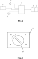
- FIG 2 is a schematic diagram of control functions of the safety system according to an embodiment of the present invention
- FIG. 3 is a schematic diagram of switched modes using a mode switching device according to an embodiment of the present invention.
- a safety system 10 includes a robot 11, a controller 12, a teaching device 13, a safety module 14, a safety function unit 15, an enabling device 16, and a mode switching device 17.
- the robot 11 has a plurality of segments 18. One end of the robot 11 is a fixed base 19, and the other end of the robot 11 is a movable end 20.
- the robot 11 is coupled to the controller 12, and the controller 12 includes the safety module 14 and the safety function unit 15.
- the controller 12 controls the end 20 of the robot 11 to move by controlling an actuator and a position sensor 21 in each segment 18.
- the controller 12 is coupled to the teaching device 13 to program the robot 11 or operate the robot 11.
- the enabling device 16 may be installed onto the teaching device 13 or the robot 11 such as the end 20, or a user may connect an independent enabling device 16 external to the controller 12, and the enabling device 16 may be installed in one or more of the above locations.
- the mode switching device 17 may be built-in in the teaching device 13 of the robot 11, or external to the controller 12.
- the safety module 14 and the safety function unit 15 are electrically or communicatively coupled to the enabling device 16, the mode switching device 17 and the position sensor 21 via the controller 12.
- the enabling device 16 may be operated in an ON state or an OFF state.
- the safety module 14 may abort a safe state of the robot 11.
- the safety module 14 may suspend the robot 11 and set the robot 11 to the safe state.
- the safety module 14 is electrically or communicatively coupled to the position sensor 21 of each segment 18 of the robot 11 and receives signals from the respective position sensors 21 to monitor the activity state of the robot 11.
- the safety module 14 may selectively set the robot 11 to one of three types of the safe state.
- the three types of the safe state include types 0, 1, and 2.
- the type 0 safe state provides a power-off shutdown function, in which when the safety module 14 determines that the robot 11 should enter the safe state, the safety module 14 shuts off the power to the actuator.
- the type 1 safe state provides an advanced power-off shutdown function, in which when the safety module 14 determines that the robot 11 should enter the safe state, the power of the actuator is shut off after a (fixed) period of time or after the robot 11 completes a speed reduction operation upon the controller 12 receiving a speed reduction command.
- the type 2 safe state provides a non-power-off shutdown function, in which when the safety module 14 determines that the robot 11 should enter the safe state, the standstill monitoring is enabled to continuously monitor the position sensor after a (fixed) period of time or after the robot 11 completes a speed reduction operation upon the controller 12 receiving a speed reduction command, and the power to the actuator is shut off upon detecting a movement of the robot.
- the safety function unit 15 may employ the controller 12 to monitor the robot 11 via the safety module 14, so as to enable one or more safety functions.
- the safety functions may include, but is not limited to, limiting an angle of movements of the segments 18, limiting a spatial position of the end 20 of the robot 11, limiting a force (or power) and limiting a speed.
- the safety module 14 sets the robot 11 into the safe state.
- various safe states of the safety module 14, various safety functions of the safety function unit 15, the enablement states of the safe states and the safety functions, and the limit parameters of the safe states and the safety functions are preset according to the requirements of each operation mode of the robot 11.
- the mode switching device 17 is a multi-position rotary switch, and the mode may be indicated by a position of the rotary switch on the teaching device 13, or displayed by a light signal.
- the mode switching device 17 may also be a software switch, a combination of hardware switches, or a combination of software and hardware switches. For example, hardware pressing or rotating enables inputting a target mode, and software enables selecting the target mode, and then hardware enables confirmation of the selected switched mode.
- the mode switching device 17 may switch between a plurality of operation modes of the robot 11.
- the operation modes include an auto mode (AUT mode), a hand-guiding mode (H mode), and a non-hand-guiding mode.
- the non-hand-guiding mode may include, but is not limited to, the manual reduced speed mode (T1 mode) and the manual high speed mode (T2 mode).
- the robot 11 when the mode switching device 17 is switched to the hand-guiding mode (H mode) by a user, the robot 11 enters a safe state. Since the user is required to continuously hand-guide the robot 11 after switching to the hand-guiding mode, the safety module 14 sets the hand-guiding mode to be the type 2 safe state for providing a non-power-off shutdown function, and then the user at least continues to press the enabling device 16 to exit the safe state and enables the hand-guiding function, and hand-guides the robot 11, for example, hand-guides the robot 11 to the next starting point of an operation, or hand-guides to demonstrate a working path, or hand-guides a collaborative robot to lift and place a weight.
- the safety module 14 sets the hand-guiding mode to be the type 2 safe state for providing a non-power-off shutdown function, and then the user at least continues to press the enabling device 16 to exit the safe state and enables the hand-guiding function, and hand-guides the robot 11, for example, hand-guides the robot 11 to the next starting point of
- the safety function unit 15 may impose various safety functions such as an angle limit of the segment 18, a spatial position limit of the end 20 of the robot 11, a force (or power) limit, and a speed limit to ensure worker safety.
- the safety module 14 presets the manual reduced speed mode to, for example, an advanced power-off shutdown function in a safe state. After the switch, the safety module 14 enters the safe state first, monitors and reacts to the enabling device 16 after confirming that the robot has stopped, the enabling device 16 being used to enable non-hand-guiding teaching or teaching verification operations, such as moving the segment 18, the robot 11, and the end 20 along with the respective axial directions of a coordinate system, performing a calibration operation on the robot 11, moving the end 20 to a specific point, or teaching a programmed operation in a single step. Since the manual reduced speed mode is a non-hand-guiding mode, the user does not work closely with the robot 11, and the strict safety protection is not required. Therefore, the safety function unit 15 may impose only safety functions such as the power (or force) limit and the speed limit.
- the safety module 14 may preset the manual high speed mode to be, for example, the type 0 safe state for providing the power-off shutdown function, the safety module 14 first enters the safe state after switching, monitors and reacts to the enabling device 16 upon ensuring that the robot 11 is shut down.
- the enabling device 16 must be continuously pressed to enable continuous enabling for, e.g., a manual trial operation. Since the manual high speed mode is a non-manual mode, the user does not work closely with the robot 11, and the strict safety protection is not required. Therefore, the safety function unit 15 may impose safety functions such as the speed limit.
- the user may use the controller 12 to control the robot 11 to perform automatic operations.
- the safety module 14 may set the manual high speed mode to be, for example, the type 0 safe state for providing the power-off shutdown function, and it is necessary to monitor abnormality in the automatic operation of the robot 11.
- the preset safety function unit 15 may be enabled to impose various safety functions such as the spatial position limitation, force limitation, and speed limitation on the end 20 of the robot 11.
- the preset safety function unit 15 may be disabled to ensure the operation efficiency.
- the robot 11 When the mode switching device 17 is switched from the manual reduced speed mode, the manual high speed mode, or the auto mode to the hand-guiding mode, the robot 11 records a breakpoint of the operation program, activates a preset safety module 14 of the type 2 safe state and a preset safety function of the hand-guiding mode, and enables the hand-guiding function.
- the mode switching device 17 In the hand-guiding mode with the specific safe state, after the user corrects a new operation by hand-guiding to teach the robot 11, the mode switching device 17 is switched back to a previous operation mode and proceeds the operation program from the breakpoint.
- the foregoing embodiments employ, but are not limited to, the preset safety modes and safety functions of each operation mode.
- FIG. 4 is a flowchart of a safety method for teaching a robot according to an embodiment of the present invention. Steps of the safety method for teaching the robot 11 in the auto mode will be explained in detail as follows:
- the safety system and method for teaching a robot of the present invention may switch between various operation modes of the robot via the mode switching device, and employ the enabling device to enable different preset safety modules and safety functions corresponding to each teaching mode to achieve simple switching between multiple operation modes.
- the safety method for teaching robots of the present invention utilizes preset safety modules and safety function switching robots corresponding to each operation mode to construct a safety system suitable for each operation mode, while ensuring that when various operation modes are switched to the hand-guiding mode, the safety system can maintain the exclusive safety module and safety function of the hand-guiding mode, to enhance the safety of users.
Landscapes
- Engineering & Computer Science (AREA)
- Robotics (AREA)
- Mechanical Engineering (AREA)
- Manipulator (AREA)
Priority Applications (1)
| Application Number | Priority Date | Filing Date | Title |
|---|---|---|---|
| EP21204402.8A EP4169671A1 (de) | 2021-10-25 | 2021-10-25 | Sicherheitssystem und verfahren zum lehren eines roboters |
Applications Claiming Priority (1)
| Application Number | Priority Date | Filing Date | Title |
|---|---|---|---|
| EP21204402.8A EP4169671A1 (de) | 2021-10-25 | 2021-10-25 | Sicherheitssystem und verfahren zum lehren eines roboters |
Publications (1)
| Publication Number | Publication Date |
|---|---|
| EP4169671A1 true EP4169671A1 (de) | 2023-04-26 |
Family
ID=78649103
Family Applications (1)
| Application Number | Title | Priority Date | Filing Date |
|---|---|---|---|
| EP21204402.8A Withdrawn EP4169671A1 (de) | 2021-10-25 | 2021-10-25 | Sicherheitssystem und verfahren zum lehren eines roboters |
Country Status (1)
| Country | Link |
|---|---|
| EP (1) | EP4169671A1 (de) |
Citations (4)
| Publication number | Priority date | Publication date | Assignee | Title |
|---|---|---|---|---|
| US20060282559A1 (en) * | 2005-05-26 | 2006-12-14 | Kabushiki Kaisha Toshiba | Apparatus, method and computer program product for executing command |
| US20150306766A1 (en) * | 2012-11-09 | 2015-10-29 | Abb Technology Ltd | Robot Control With Improved Safety |
| EP2958711A1 (de) * | 2013-02-21 | 2015-12-30 | ABB Technology Ltd. | Industrierobotersystem mit einer aktivierungseinheit und mehreren allzweckvorrichtungen sowie verfahren zur steuerung des robotersystems |
| WO2021078345A1 (en) * | 2019-10-22 | 2021-04-29 | Universal Robots A/S | Maintaining free-drive mode of robot arm for period of time |
-
2021
- 2021-10-25 EP EP21204402.8A patent/EP4169671A1/de not_active Withdrawn
Patent Citations (4)
| Publication number | Priority date | Publication date | Assignee | Title |
|---|---|---|---|---|
| US20060282559A1 (en) * | 2005-05-26 | 2006-12-14 | Kabushiki Kaisha Toshiba | Apparatus, method and computer program product for executing command |
| US20150306766A1 (en) * | 2012-11-09 | 2015-10-29 | Abb Technology Ltd | Robot Control With Improved Safety |
| EP2958711A1 (de) * | 2013-02-21 | 2015-12-30 | ABB Technology Ltd. | Industrierobotersystem mit einer aktivierungseinheit und mehreren allzweckvorrichtungen sowie verfahren zur steuerung des robotersystems |
| WO2021078345A1 (en) * | 2019-10-22 | 2021-04-29 | Universal Robots A/S | Maintaining free-drive mode of robot arm for period of time |
Non-Patent Citations (2)
| Title |
|---|
| TECHMAN ROBOT: "Safety Manual", 2 April 2019 (2019-04-02), XP055902671, Retrieved from the Internet <URL:https://uchimurarobotics.com/wp-content/uploads/2020/01/Safety-Manual_TECHMAN-ROBOT-Safety-system.pdf> [retrieved on 20220317] * |
| TECHMAN ROBOT: "Software Manual TMflow Original Instruction", 13 December 2019 (2019-12-13), XP055903060, Retrieved from the Internet <URL:https://accu-techusa.com/wp-content/uploads/2021/01/Software-Manual-TMflow_SW1.76_Rev1.00_EN.pdf> [retrieved on 20220318] * |
Similar Documents
| Publication | Publication Date | Title |
|---|---|---|
| US9802286B2 (en) | Robot control system provided in machining system including robot and machine tool | |
| EP0192157B2 (de) | Numerisch gesteuerte Werkzeugmaschine mit Haltbefehl im Falle eines Fehlers | |
| JP2812582B2 (ja) | 産業用ロボットの制御装置 | |
| US20090058342A1 (en) | Robot controller having stoppage monitoring function | |
| JPWO2004009303A1 (ja) | ロボット制御装置およびロボットシステム | |
| JP2016179510A (ja) | 物または人との接触を検知する機能を有するロボット制御装置 | |
| US20230122989A1 (en) | Safety system and method for teaching a robot | |
| EP1785236B1 (de) | Ausgangsanpassungsverfahren für einen industrieroboter | |
| US11193987B2 (en) | Control system of industrial machine | |
| JP4200889B2 (ja) | ロボットシステム | |
| JP2005151729A (ja) | 制御装置 | |
| JPH08263113A (ja) | 異常処理制御装置 | |
| CN113985811B (zh) | 一种数控机床防碰撞控制方法及数控机床 | |
| US20220258350A1 (en) | Robot Monitoring Apparatus And Robot System | |
| CN105555488B (zh) | 操作装置 | |
| US20060202556A1 (en) | Control device for automatic machine | |
| CN113799176A (zh) | 教导机器人的安全系统及方法 | |
| JP2007283448A (ja) | ロボット制御装置 | |
| TW202146195A (zh) | 教導機器人的安全系統及方法 | |
| US11667037B2 (en) | Robot system with hand-guiding function | |
| EP4434688A1 (de) | Steuerungsverfahren, robotersystem und nichtflüchtiges computerlesbares speichermedium mit darauf gespeichertem programm | |
| JPH1133867A (ja) | 工作機械の工具干渉保護方法及び保護装置 | |
| JP3366248B2 (ja) | ロボットの制御方法および装置 | |
| KR100440154B1 (ko) | 공작기계의 이송축 오버트래블 제어방법 | |
| JP2004268216A (ja) | 安全保護手段を有する自動機械装置 |
Legal Events
| Date | Code | Title | Description |
|---|---|---|---|
| PUAI | Public reference made under article 153(3) epc to a published international application that has entered the european phase |
Free format text: ORIGINAL CODE: 0009012 |
|
| STAA | Information on the status of an ep patent application or granted ep patent |
Free format text: STATUS: REQUEST FOR EXAMINATION WAS MADE |
|
| 17P | Request for examination filed |
Effective date: 20220712 |
|
| AK | Designated contracting states |
Kind code of ref document: A1 Designated state(s): AL AT BE BG CH CY CZ DE DK EE ES FI FR GB GR HR HU IE IS IT LI LT LU LV MC MK MT NL NO PL PT RO RS SE SI SK SM TR |
|
| STAA | Information on the status of an ep patent application or granted ep patent |
Free format text: STATUS: EXAMINATION IS IN PROGRESS |
|
| 17Q | First examination report despatched |
Effective date: 20240313 |
|
| STAA | Information on the status of an ep patent application or granted ep patent |
Free format text: STATUS: THE APPLICATION HAS BEEN WITHDRAWN |
|
| 18W | Application withdrawn |
Effective date: 20240409 |