EP4169694B1 - Procédé et dispositif de moulage par soufflage de récipients avec partie fond mobile - Google Patents
Procédé et dispositif de moulage par soufflage de récipients avec partie fond mobile Download PDFInfo
- Publication number
- EP4169694B1 EP4169694B1 EP22202323.6A EP22202323A EP4169694B1 EP 4169694 B1 EP4169694 B1 EP 4169694B1 EP 22202323 A EP22202323 A EP 22202323A EP 4169694 B1 EP4169694 B1 EP 4169694B1
- Authority
- EP
- European Patent Office
- Prior art keywords
- pressure
- pressure level
- valve
- reservoir
- level
- Prior art date
- Legal status (The legal status is an assumption and is not a legal conclusion. Google has not performed a legal analysis and makes no representation as to the accuracy of the status listed.)
- Active
Links
Images


Classifications
-
- B—PERFORMING OPERATIONS; TRANSPORTING
- B29—WORKING OF PLASTICS; WORKING OF SUBSTANCES IN A PLASTIC STATE IN GENERAL
- B29C—SHAPING OR JOINING OF PLASTICS; SHAPING OF MATERIAL IN A PLASTIC STATE, NOT OTHERWISE PROVIDED FOR; AFTER-TREATMENT OF THE SHAPED PRODUCTS, e.g. REPAIRING
- B29C49/00—Blow-moulding, i.e. blowing a preform or parison to a desired shape within a mould; Apparatus therefor
- B29C49/18—Blow-moulding, i.e. blowing a preform or parison to a desired shape within a mould; Apparatus therefor using several blowing steps
-
- B—PERFORMING OPERATIONS; TRANSPORTING
- B29—WORKING OF PLASTICS; WORKING OF SUBSTANCES IN A PLASTIC STATE IN GENERAL
- B29C—SHAPING OR JOINING OF PLASTICS; SHAPING OF MATERIAL IN A PLASTIC STATE, NOT OTHERWISE PROVIDED FOR; AFTER-TREATMENT OF THE SHAPED PRODUCTS, e.g. REPAIRING
- B29C49/00—Blow-moulding, i.e. blowing a preform or parison to a desired shape within a mould; Apparatus therefor
- B29C49/08—Biaxial stretching during blow-moulding
- B29C49/10—Biaxial stretching during blow-moulding using mechanical means for prestretching
- B29C49/12—Stretching rods
-
- B—PERFORMING OPERATIONS; TRANSPORTING
- B29—WORKING OF PLASTICS; WORKING OF SUBSTANCES IN A PLASTIC STATE IN GENERAL
- B29C—SHAPING OR JOINING OF PLASTICS; SHAPING OF MATERIAL IN A PLASTIC STATE, NOT OTHERWISE PROVIDED FOR; AFTER-TREATMENT OF THE SHAPED PRODUCTS, e.g. REPAIRING
- B29C49/00—Blow-moulding, i.e. blowing a preform or parison to a desired shape within a mould; Apparatus therefor
- B29C49/28—Blow-moulding apparatus
-
- B—PERFORMING OPERATIONS; TRANSPORTING
- B29—WORKING OF PLASTICS; WORKING OF SUBSTANCES IN A PLASTIC STATE IN GENERAL
- B29C—SHAPING OR JOINING OF PLASTICS; SHAPING OF MATERIAL IN A PLASTIC STATE, NOT OTHERWISE PROVIDED FOR; AFTER-TREATMENT OF THE SHAPED PRODUCTS, e.g. REPAIRING
- B29C49/00—Blow-moulding, i.e. blowing a preform or parison to a desired shape within a mould; Apparatus therefor
- B29C49/42—Component parts, details or accessories; Auxiliary operations
- B29C49/4284—Means for recycling or reusing auxiliaries or materials, e.g. blowing fluids or energy
- B29C49/42845—Recycling or reusing of fluid, e.g. pressure
-
- B—PERFORMING OPERATIONS; TRANSPORTING
- B29—WORKING OF PLASTICS; WORKING OF SUBSTANCES IN A PLASTIC STATE IN GENERAL
- B29C—SHAPING OR JOINING OF PLASTICS; SHAPING OF MATERIAL IN A PLASTIC STATE, NOT OTHERWISE PROVIDED FOR; AFTER-TREATMENT OF THE SHAPED PRODUCTS, e.g. REPAIRING
- B29C49/00—Blow-moulding, i.e. blowing a preform or parison to a desired shape within a mould; Apparatus therefor
- B29C49/42—Component parts, details or accessories; Auxiliary operations
- B29C49/4289—Valve constructions or configurations, e.g. arranged to reduce blowing fluid consumption
-
- B—PERFORMING OPERATIONS; TRANSPORTING
- B29—WORKING OF PLASTICS; WORKING OF SUBSTANCES IN A PLASTIC STATE IN GENERAL
- B29C—SHAPING OR JOINING OF PLASTICS; SHAPING OF MATERIAL IN A PLASTIC STATE, NOT OTHERWISE PROVIDED FOR; AFTER-TREATMENT OF THE SHAPED PRODUCTS, e.g. REPAIRING
- B29C49/00—Blow-moulding, i.e. blowing a preform or parison to a desired shape within a mould; Apparatus therefor
- B29C49/42—Component parts, details or accessories; Auxiliary operations
- B29C49/78—Measuring, controlling or regulating
- B29C49/783—Measuring, controlling or regulating blowing pressure
-
- B—PERFORMING OPERATIONS; TRANSPORTING
- B29—WORKING OF PLASTICS; WORKING OF SUBSTANCES IN A PLASTIC STATE IN GENERAL
- B29C—SHAPING OR JOINING OF PLASTICS; SHAPING OF MATERIAL IN A PLASTIC STATE, NOT OTHERWISE PROVIDED FOR; AFTER-TREATMENT OF THE SHAPED PRODUCTS, e.g. REPAIRING
- B29C49/00—Blow-moulding, i.e. blowing a preform or parison to a desired shape within a mould; Apparatus therefor
- B29C49/42—Component parts, details or accessories; Auxiliary operations
- B29C49/48—Moulds
- B29C2049/4879—Moulds characterised by mould configurations
- B29C2049/4892—Mould halves consisting of an independent main and bottom part
-
- B—PERFORMING OPERATIONS; TRANSPORTING
- B29—WORKING OF PLASTICS; WORKING OF SUBSTANCES IN A PLASTIC STATE IN GENERAL
- B29C—SHAPING OR JOINING OF PLASTICS; SHAPING OF MATERIAL IN A PLASTIC STATE, NOT OTHERWISE PROVIDED FOR; AFTER-TREATMENT OF THE SHAPED PRODUCTS, e.g. REPAIRING
- B29C49/00—Blow-moulding, i.e. blowing a preform or parison to a desired shape within a mould; Apparatus therefor
- B29C49/42—Component parts, details or accessories; Auxiliary operations
- B29C49/78—Measuring, controlling or regulating
- B29C49/783—Measuring, controlling or regulating blowing pressure
- B29C2049/7832—Blowing with two or more pressure levels
- B29C2049/7833—Blowing with three or more pressure levels
-
- B—PERFORMING OPERATIONS; TRANSPORTING
- B29—WORKING OF PLASTICS; WORKING OF SUBSTANCES IN A PLASTIC STATE IN GENERAL
- B29C—SHAPING OR JOINING OF PLASTICS; SHAPING OF MATERIAL IN A PLASTIC STATE, NOT OTHERWISE PROVIDED FOR; AFTER-TREATMENT OF THE SHAPED PRODUCTS, e.g. REPAIRING
- B29C49/00—Blow-moulding, i.e. blowing a preform or parison to a desired shape within a mould; Apparatus therefor
- B29C49/02—Combined blow-moulding and manufacture of the preform or the parison
- B29C49/06—Injection blow-moulding
-
- B—PERFORMING OPERATIONS; TRANSPORTING
- B29—WORKING OF PLASTICS; WORKING OF SUBSTANCES IN A PLASTIC STATE IN GENERAL
- B29K—INDEXING SCHEME ASSOCIATED WITH SUBCLASSES B29B, B29C OR B29D, RELATING TO MOULDING MATERIALS OR TO MATERIALS FOR MOULDS, REINFORCEMENTS, FILLERS OR PREFORMED PARTS, e.g. INSERTS
- B29K2067/00—Use of polyesters or derivatives thereof, as moulding material
- B29K2067/003—PET, i.e. poylethylene terephthalate
-
- B—PERFORMING OPERATIONS; TRANSPORTING
- B29—WORKING OF PLASTICS; WORKING OF SUBSTANCES IN A PLASTIC STATE IN GENERAL
- B29L—INDEXING SCHEME ASSOCIATED WITH SUBCLASS B29C, RELATING TO PARTICULAR ARTICLES
- B29L2031/00—Other particular articles
- B29L2031/712—Containers; Packaging elements or accessories, Packages
- B29L2031/7158—Bottles
Definitions
- the present invention relates to a method and a device for forming plastic preforms into plastic containers and in particular plastic bottles according to the respective preambles of the independent claims 1 and 10.
- Such methods and devices have long been known from the prior art.
- heated plastic preforms are usually introduced into blow molds and pressurized within these blow molds so that a plastic container or a plastic bottle can be formed.
- the plastic preforms are usually subjected to different pressure levels. For example, it is known that a pre-blow pressure is first applied, which serves to initially expand the container, then an intermediate blow pressure and finally a final blow pressure.
- a so-called stretch rod is inserted into the containers in order to expand them.
- the method is characterized in that pressure channels of at least two pressure reservoirs can be connected to one another and/or are connected via a connecting valve, so that by means of this pressure channel assigned to the connecting valve, at least two pressures of pressure channels can be recycled in a controlled and/or regulated manner, in particular wherein two compressed air reservoirs are filled via a single valve, for example the connecting valve.
- a forming process is carried out within a clean room. It is also known to sterilize before or after the blow molding process by applying a sterilization medium, such as hydrogen peroxide.
- the compressed air required in particular in the blow molding machine or its generation is energy-intensive and therefore accounts for a large proportion of the operating costs in a blow molding machine and in particular a stretch blow molding machine.
- pressures of up to 40 bar are required to produce PET bottles from plastic preforms.
- Savings potential arises from various approaches to reusing the compressed air generated at certain pressure levels, i.e. recycling.
- different pressure levels are used for the expansion process of the plastic preforms and, for example, the pressure from a higher pressure level can be recycled to a lower pressure level.
- the applicant has developed such compressed air recycling systems for stretch blow molding machines, which, depending on the design, reuse parts of the compressed air internally in the machine, but are also partly available for external applications. Such devices are known from the applicant's internal state of the art.
- P1 as the pre-blow pressure level
- Pi as the intermediate blow pressure level
- P2 as the finished blow pressure level.
- Each of these pressure levels has its own ring channel and a valve on the valve block of the blow station in order to be able to direct the pressure into the customer object (preform/bottle).
- the valve block of the new Contiform NX generation is to have a fifth valve.
- the task of the fifth valve is to create an additional pressure level between P1 and Pi or P2. This additional pressure level allows an increased recycling potential to be used at higher P2 pressures and low P1 pressures.
- the relief pressure pex at the beginning of the exhaust valve switching is crucial for the air consumption. If this pressure is very close to the P1 pressure level, This means that the maximum amount of recycled air is used to build up pressure internally and the air consumption is minimal.
- a disadvantage of the state of the art or the second intermediate pressure level is the extended time until the P2 pressure level is reached and the extended time when recycling the pressure levels. Due to the fact that each pressure level in the bottle has to develop to a certain extent and the physical fact that the flow rate slows down significantly shortly before the pressure level in the bottle is reached, it is clear that both in the pressure build-up there is an extension of the pressure build-up to P2 and in recycling there is an extension of the recycling time, which leads to a reduction in the P2 holding time.
- the P1 recycling must also flow through a pre-blowing throttle.
- This pre-blowing throttle has the task of limiting the volume flow when pressure builds up.
- a recycling process that is as fast as possible would be desirable and the pre-blowing throttle would be a hindrance.
- the present invention is therefore based on the object of enabling a minimization of energy and/or resource consumption during the forming of plastic preforms into plastic bottles in a cost-effective manner.
- a connection between the pressure reservoir of the first pressure level and a connection between the pressure reservoir of the second pressure level can be established and severed.
- a regulated and/or controlled valve and/or a pairing of a shut-off valve and a regulated and/or controlled throttle valve is arranged between the pressure reservoir of the first pressure level and the pressure reservoir of the second pressure level.
- valve block This can mean that five valves (pre-blowing, two intermediate blowings, final blowing and exhaust) are arranged on the valve block.
- At least one of the pressures can be conducted by means of the valve block in such a way that at least a portion of these pressures can be recycled, that is to say, among other things, can be restored.
- blowing means the introduction of compressed air into a plastic preform in order to inflate it to the size of a container.
- the compressed air to be recycled can be guided by the valve block in such a way that the compressed air to be recycled flows into a pressure reservoir with a lower pressure level (... and thus refills it).
- At least one valve is provided for generating a pressure level within the pressure reservoir associated with the pressure level, so that the pressure levels are generated by controlling the valves.
- the second pressure level is provided by a single pressure reservoir or by at least two separate pressure reservoirs.
- a pressure level can be a pressure value of a fluid within a pressure channel, whereby a pressure channel is an at least partially fluid-tight line volume for conducting the fluid.
- the second pressure corresponds to an intermediate blowing pressure
- the second pressure corresponds to a p+ pressure within a p+ pressure stage or the p+ pressure corresponds to an additional intermediate blowing pressure in addition to the intermediate blowing pressure already present or to be approached.
- the second pressure level is provided by a single pressure reservoir or by at least two separate pressure reservoirs
- the additional valve of the p+ pressure channel is arranged at that location of the p+ pressure channel which corresponds to a fluidic connection between the p+ pressure channel and a p1 and/or p2 pressure channel, so that a pressure of the p1 pressure channel and/or a pressure of the p2 pressure channel is at least partially recycled via the p+ pressure channel.
- At least one of the pressure reservoirs are formed by at least one annular channel.
- the connecting valve is a dome pressure regulator valve or a regulated 2/2-way valve or a shut-off valve with a downstream regulated throttle.
- Dome pressure regulators are operated using gas pressure.
- the opening force of the valve required to reduce the pressure is not generated by a spring, but by the pressure of a so-called control gas / pilot gas.
- the gas to be regulated is fed through the line into the dome, where it hits a valve seat.
- the control gas is controlled by a built-in control pressure regulator and thus fed into the pressure chamber.
- Dome pressure regulator sets can therefore be closed systems and allow the working pressure to be increased or reduced at any time, even during operation.
- 2/2-way valves are opening and closing valves that open or close the path of the working medium. These valves can be either closed or open in the basic position.
- the 2/2-way valve can be operated electrically, pneumatically or electro-pneumatically.
- the p1 pressure channel is at least partially, preferably completely, fed via the p+ pressure channel.
- the present invention additionally relates to a device for forming plastic preforms into plastic bottles, wherein the device is particularly designed and intended to carry out the method according to at least one of the preceding embodiments. This can mean that all features disclosed for the method described here are also apparent for the device described here and vice versa.
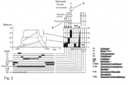
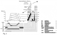
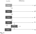
- FIG. 1 shows a ring channel P1 according to the current state of the art, with Figure 2a showing the inventive concept within the framework of a "quality” operating method and Figure 2b showing the inventive concept described here within the framework of an "efficiency” method with the corresponding arrows and the corresponding valves.
- the approach is that the machine operator has the option of using the fifth valve and the associated ring channel variably, even if the hardware is the same. If it is technically possible If it is necessary to have short rise times and recycling times, the "Quality" approach should be chosen, in which the fifth valve is used as a recycling valve for the P1 pressure level. This means that when recycling the P1 pressure level, recycling does not have to be carried out through the P1 throttle and faster P1 recycling is possible. The additional second intermediate pressure level is also completely eliminated. Furthermore, the P1 pressure level has an increased volume due to the second ring channel, which has been proven to reduce pressure fluctuations in the P1 pressure level and reduce fluctuations in the segment weights.
- the supply of P1 air from the P+ air can be controlled/regulated using an intermediate valve between p+ (fifth valve) and p1.
- the Figure 2 can be a corresponding pressure curve diagram within the framework of a "quality" procedure as well as a, in the upper right part of the figure, schematic structure of various ring channels (corresponds to the circles) as well as further corresponding reducing units and a rotary distributor (upper large circle of the Figure 3 ) to be shown.
- the individual pressure curves in particular the corresponding response of the individual ring channels, are given via the transfer diagram from the blowing curve into the corresponding control times/control pressures relative to time t (see grid pattern).
- the machine operator can also select the "Efficiency" option, where an additional second intermediate blowing pressure level is activated with p+ or the fifth valve.
- recycling is carried out conventionally through the P1 throttle and each ring channel is switched on in the usual way, both in the pressure and recycling phases.
- the intermediate valve between p+ and p1 is closed so that no air exchange can take place. If, for unforeseen reasons, p1 needs to be supplied with fresh air, the intermediate valve is opened briefly and air can flow from the higher pressure level p+ to p1 until the fresh air requirement is met.
- each ring channel pressure is supplied with fresh air as required via a dome pressure regulator (P+D, P1).
- P+D dome pressure regulator
- P1 pressure level a dome pressure regulator would also be necessary for feeding.
- a directional control valve or a conventional dome pressure regulator could be used as a connection between P+ and P1, which then does not reduce from compressor high pressure to the desired P1 pressure level, but "only" from P+ pressure level.
- the black box valve/dome In the Quality approach with a direct connection of the ring channels P+ and P1, the black box valve/dome would be open at least temporarily. This means that an air/pressure exchange between p+ and P1 would be possible. In the Efficiency approach, the black box valve/dome would be closed and each pressure stage would be filled "only” by recycling the blowing air. If a fault occurs or recycling is not sufficient to completely fill P1, the dome in P1 would have to open briefly and allow a volume flow to P1. However, this would result in increased fluctuation in P1 due to the high pressure delta between the compressor high pressure and P1 pressure.
- the Quality approach with a direct connection between the ring channels P+ and P1 would see the black box valve open at least temporarily, preferably permanently. In other words, an air/pressure exchange between p+ and P1 would be possible.
- the black box valve would be closed and each pressure stage would be filled "only” by recycling the blowing air. If a fault occurs or recycling is not sufficient to completely fill P1, the black box valve would have to open briefly and allow air to flow from p+ to P1. The fluctuation of the p+ ring channel would thus be increased, but would not be as critical in terms of process technology as in the p1 ring channel.
- P1 pre-blow pressure level
- Pi intermediate blow pressure level
- P2 finished blow pressure level
- Each of these pressure levels has its own ring channel in at least one embodiment. and a valve on a valve block of the blowing station to direct the pressure into a plastic preform and/or a bottle.
- valve block presented here is intended to have a connecting valve, also as a fifth valve.
- the task of the connecting valve is, in at least one embodiment, to create an additional pressure level between the pressures P1 and Pi or P2. This additional pressure level allows an increased recycling potential to be utilized at higher P2 pressures and low P1 pressures.
- the relief pressure pex when the exhaust valve starts switching is crucial for air consumption. If this pressure is very close to the P1 pressure level, this means that the maximum amount of recycled air is used internally to build up pressure and air consumption is minimal.
- the combination also overcomes a disadvantage of the prior art, namely that the second intermediate pressure stage, which is extended, and therefore takes time to reach the P2 pressure level and the extended time for recycling the pressure stages, slows down the blowing process. Due to the fact that each pressure stage in the bottle has to develop to a certain extent and the physical fact that the flow rate slows down significantly shortly before the pressure stage in the bottle is reached, it is clear that both in the pressure build-up there is an extension of the pressure build-up to P2 and in recycling there is an extension of the recycling time, which leads to a reduction in the P2 holding time.
- the P1 recycling must also flow through a pre-blowing throttle.
- This pre-blowing throttle has the task of limiting the volume flow when pressure builds up.
- a recycling process that is as fast as possible would be desirable and the pre-blowing throttle would be a hindrance.
- a key point of the invention is to variably adjust the fifth valve during the blowing process.
- One approach is therefore to use the fifth valve as a recycling valve of P1, i.e. the pressure stage P1, so that in at least one possible embodiment a connection exists between an annular channel of the fifth valve and a P1 annular channel and the fifth valve applies an intermediate pressure and the connection to P1, i.e. the P1 pressure stage, is separated.
- the approach is that the machine operator has the option of using the fifth valve and the associated ring channel variably without changing the hardware.
- the P1 pressure level has an increased volume due to the second ring channel (i.e. the p+ ring channel), which has been proven to reduce pressure fluctuations in the P1 pressure level and reduce fluctuations in segment weights.
- the second ring channel i.e. the p+ ring channel
- the supply of P1 air can be controlled/regulated from the P+ pressure stage.
- the machine operator can also select the "Efficiency" option, in which an additional second intermediate blowing pressure level is activated with p+ or the fifth valve.
- recycling is carried out conventionally through the P1 throttle and each ring channel is switched on in the conventional way, both in the pressure and recycling phases.
- the maximum amount of air can be recycled and air consumption can be kept to a minimum.
- the intermediate valve between the p+ pressure level and the p1 pressure level is closed so that no air exchange can take place. If, for unforeseen reasons, the p1 pressure channel needs to be supplied with fresh air, the intermediate valve is opened briefly and air can flow from the higher pressure level p+ to p1 until the fresh air requirement is met.
- This connection of the ring channels can be made using a 2/2-way valve, for example, which is stable at 40 bar.
- a dome pressure regulator could also be used as a shut-off device.
- each ring channel pressure is supplied with fresh air as required via a dome pressure regulator.
- a dome pressure regulator would also be necessary for supply.
- both a directional valve and a dome pressure regulator would be conceivable, which then does not reduce from compressor high pressure to the desired P1 pressure level, but "only" from P+ pressure level.
- the second embodiment would omit the dome pressure regulator in the P1 pressure channel and only allow the P1 pressure level to be fed from the P+ pressure level.
- the concept could be supplemented with the P2 feed from P3 in order to always have only three dome pressure regulators. This is analogous to the "efficiency" approach of the P1 ring channel and will not be described further below, but would be technically possible and certainly sensible.
- the valve in the "Quality" approach with a direct connection of the ring channels P+ and P1 the valve is open at least temporarily, preferably permanently. In other words, an air/pressure exchange between p+ and P1 would be possible. In the "Efficiency” approach the valve would then be closed and each pressure stage would be filled “only” by recycling the blowing air. If a fault occurs or the recycling is not sufficient to completely fill P1, the valve would have to open briefly and allow air to flow from p+ to P1. The fluctuation of the p+ ring channel would thus be increased, but would not be as critical in terms of process technology as in the p1 ring channel.
Landscapes
- Engineering & Computer Science (AREA)
- Manufacturing & Machinery (AREA)
- Mechanical Engineering (AREA)
- Life Sciences & Earth Sciences (AREA)
- Sustainable Development (AREA)
- Blow-Moulding Or Thermoforming Of Plastics Or The Like (AREA)
Claims (10)
- Procédé de formage d'ébauches en matière plastique en bouteilles en matière plastique avec les étapes suivantes :- l'introduction d'une ébauche en matière plastique (10) à expanser dans un moule de soufflage, dans lequel ce moule de soufflage présente au moins deux parties latérales (14) et une partie de fond (18) ;- l'insertion d'une tige d'étirage (34) par l'embouchure de l'ébauche en matière plastique (10) à l'intérieur de l'ébauche en matière plastique (10) afin d'étirer celle-ci dans son sens longitudinal (L) ;- l'alimentation de l'ébauche en matière plastique (10) en un premier niveau de pression (P1) ;- l'alimentation de l'ébauche en matière plastique (10) en au moins un deuxième niveau de pression (P+, Pi), dans lequel le deuxième niveau de pression (P+, Pi) diverge du premier niveau de pression (P1) et est de préférence supérieur au premier niveau de pression (P1),- l'alimentation de l'ébauche en matière plastique (10) en un troisième niveau de pression (P2), dans lequel ce troisième niveau de pression (P2) diverge du deuxième niveau de pression (P+) et est de préférence supérieur au deuxième niveau de pression (P+), dans lequel un réservoir de pression est associé à chaque niveau de pression,dans lequel le procédé présente un premier et un second mode de fonctionnement,dans lequel les modes de fonctionnement respectifs sont sélectionnés au choix par un utilisateur, selon l'exigence,caractérisé en ce quedans le premier mode de fonctionnement, donc dans un mode de qualité, une liaison entre un bloc soupapes et un réservoir de pression du deuxième niveau de pression (P+, Pi) est établie dans une seule direction, d'un bloc soupapes en direction du réservoir de pression, donc un recyclage d'air comprimé, etdans un second mode de fonctionnement, donc une approche d'efficience, une liaison entre le bloc soupapes et le réservoir de pression du deuxième niveau de pression (P+, Pi) est établie dans les deux directions, donc du bloc soupapes en direction du réservoir de pression et du réservoir de pression en direction du bloc soupapes.
- Procédé selon la revendication 1,
caractérisé en ce que
une liaison entre le réservoir de pression du premier niveau de pression et une liaison entre le réservoir de pression du deuxième niveau de pression peuvent être établies et séparées. - Procédé selon la revendication 1 ou 2,
caractérisé en ce que
une soupape régulée et/ou une soupape commandée et/ou un appariement d'une soupape de blocage et d'une soupape d'étranglement régulée et/ou commandée est agencée entre le réservoir de pression du premier niveau de pression et le réservoir de pression du deuxième niveau de pression. - Procédé selon au moins l'une quelconque des revendications précédentes,
caractérisé en ce que
pendant un soufflage, de l'air comprimé d'étages de pression individuels au moins d'une des pressions (P2, Pi, P1) peut être acheminé au moyen du bloc soupapes de telle manière qu'au moins une partie de ces pressions puisse être recyclée, c'est-à-dire récupérée entre autres. - Procédé selon au moins l'une quelconque des revendications précédentes,
caractérisé en ce que
des canaux de pression au moins de deux réservoirs de pression peuvent être reliés et/ou sont reliés par le biais d'une soupape de liaison (V5) entre eux de sorte qu'au moyen de ce un canal de pression associé à la soupape de liaison (V5), au moins deux pressions de canaux de pression peuvent être recyclées de manière commandée et/ou régulée l'une par rapport à l'autre, en particulier dans lequel un remplissage de deux réservoirs d'air comprimé est effectué par le biais d'une seule soupape, par exemple la soupape de liaison (V5). - Procédé selon au moins l'une quelconque des revendications précédentes,
caractérisé en ce que
au moins une soupape est prévue pour la génération d'un niveau de pression à l'intérieur d'un réservoir de pression associé aux niveaux de pression de sorte que les niveaux de pression soient générés au moyen d'une commande des soupapes. - Procédé selon au moins l'une quelconque des revendications précédentes,
caractérisé en ce que
le deuxième niveau de pression (P+) est fourni par un seul réservoir de pression ou par au moins deux réservoirs de pression séparés. - Procédé selon au moins l'une quelconque des revendications précédentes,
caractérisé en ce que
la soupape de liaison est une soupape de régulation de pression à dôme ou une soupape 2/2 voies régulée ou une soupape de blocage avec un étranglement régulé logé en aval. - Procédé selon au moins l'une quelconque des revendications précédentes,
caractérisé en ce que
le canal de pression P1 est alimenté au moins partiellement, de préférence complètement, par le biais du canal de pression P+. - Dispositif de formage d'ébauches en matière plastique en bouteilles en matière plastique avec au moins un dispositif de transport (2), au niveau duquel une pluralité de postes de formage (20) est agencée, dans lequel chacun de ces postes de formage présente un moule de soufflage qui présente respectivement deux parties latérales (14) mobiles l'une par rapport à l'autre pour l'ouverture et la fermeture du moule de soufflage ainsi qu'une partie de fond (18), dans lequel une tige d'étirage est agencée au niveau de chaque poste de formage et dans lequel le dispositif (1) présente en outre au moins un dispositif d'alimentation afin d'alimenter les ébauches en matière plastique pour leur expansion en un milieu gazeux ainsi qu'un dispositif de commande qui commande l'alimentation des ébauches en matière plastique en milieu gazeux de manière à alimenter ceux-ci tout d'abord en un premier niveau de pression (P1), ensuite en au moins un deuxième niveau de pression (Pi) qui se trouve au-dessus du premier niveau de pression (P1) et finalement en un troisième niveau de pression (P2) qui se trouve de préférence au-dessus du deuxième niveau de pression (Pi), dans lequelun réservoir de pression est associé à chaque niveau de pression,dans lequel le dispositif peut fonctionner dans au moins un premier et un second mode de fonctionnement, dans lequel les modes de fonctionnement respectifs peuvent être sélectionnés au choix par un utilisateur, selon l'exigence, et en outre dans lequeldans le premier mode de fonctionnement, donc dans un mode de qualité, une liaison entre un bloc soupapes et un réservoir de pression du deuxième niveau de pression peut être établie dans une seule direction, d'un bloc soupapes en direction du réservoir de pression, donc un recyclage d'air comprimé, et dans un second mode de fonctionnement, donc une approche d'efficience, une liaison entre le bloc soupapes et le réservoir de pression du deuxième niveau de pression peut être établie dans les deux directions, donc du bloc soupapes en direction du réservoir de pression et du réservoir de pression en direction du bloc de soupapes, en particulier dans lequel le deuxième niveau de pression (P+) est fourni par un seul réservoir de pression ou par au moins deux réservoirs de pression séparés.
Applications Claiming Priority (1)
| Application Number | Priority Date | Filing Date | Title |
|---|---|---|---|
| DE102021127436.2A DE102021127436A1 (de) | 2021-10-21 | 2021-10-21 | Verfahren und Vorrichtung zum Blasformen von Behältnissen mit beweglichem Bodenteil |
Publications (2)
| Publication Number | Publication Date |
|---|---|
| EP4169694A1 EP4169694A1 (fr) | 2023-04-26 |
| EP4169694B1 true EP4169694B1 (fr) | 2024-07-24 |
Family
ID=83902739
Family Applications (1)
| Application Number | Title | Priority Date | Filing Date |
|---|---|---|---|
| EP22202323.6A Active EP4169694B1 (fr) | 2021-10-21 | 2022-10-18 | Procédé et dispositif de moulage par soufflage de récipients avec partie fond mobile |
Country Status (4)
| Country | Link |
|---|---|
| US (1) | US20230131230A1 (fr) |
| EP (1) | EP4169694B1 (fr) |
| CN (1) | CN116001243A (fr) |
| DE (1) | DE102021127436A1 (fr) |
Families Citing this family (1)
| Publication number | Priority date | Publication date | Assignee | Title |
|---|---|---|---|---|
| FR3150978B1 (fr) * | 2023-07-13 | 2025-06-06 | Sidel Participations | Procede de fabrication de corps creux avec recyclage du fluide de formage |
Family Cites Families (9)
| Publication number | Priority date | Publication date | Assignee | Title |
|---|---|---|---|---|
| DE202004021780U1 (de) | 2004-03-25 | 2010-12-09 | Krones Ag | Vorrichtung zum Herstellen eines insbesondere wärmebeständigen Hohlkörpers |
| US20080191394A1 (en) * | 2007-02-09 | 2008-08-14 | Ebac Limited | Blow moulding apparatus and method |
| DE102011110962A1 (de) | 2011-08-18 | 2013-02-21 | Khs Corpoplast Gmbh | Verfahren und Vorrichtung zur Blasformung von Behältern |
| DE102012106916A1 (de) * | 2012-07-30 | 2014-05-22 | Krones Ag | Vorrichtung und Verfahren zum Umformen von Kunststoffvorformlingen mit getrennten Strömungswegen für Blasluft und Steuerluft |
| DE102012110023A1 (de) * | 2012-10-19 | 2014-04-24 | Krones Ag | Blasmaschine mit variablem Zwischendruckniveau |
| DE102014115645A1 (de) * | 2014-10-28 | 2016-04-28 | Krones Ag | Verfahren und Vorrichtung zum Umformen von Kunststoffvorformlingen mit Querschnittsveränderung eines Volumenstroms |
| DE102016125654A1 (de) * | 2016-12-23 | 2018-06-28 | Krones Ag | Verfahren und Vorrichtung zum Blasformen von Behältnissen mit beweglichem Bodenteil |
| DE102019131188A1 (de) * | 2019-11-19 | 2021-05-20 | Krones Aktiengesellschaft | Vorrichtung zum Umformen von Kunststoffvorformlingen zu Kunststoffbehältnissen mit Proportionalventil |
| EP3888884B1 (fr) * | 2020-03-30 | 2022-05-04 | Gea Procomac S.p.A. | Appareil et procédé de formation aseptique de récipients à partir de parisons en matière thermoplastique |
-
2021
- 2021-10-21 DE DE102021127436.2A patent/DE102021127436A1/de active Pending
-
2022
- 2022-10-11 US US17/963,971 patent/US20230131230A1/en active Pending
- 2022-10-18 EP EP22202323.6A patent/EP4169694B1/fr active Active
- 2022-10-21 CN CN202211295106.XA patent/CN116001243A/zh active Pending
Also Published As
| Publication number | Publication date |
|---|---|
| CN116001243A (zh) | 2023-04-25 |
| EP4169694A1 (fr) | 2023-04-26 |
| US20230131230A1 (en) | 2023-04-27 |
| DE102021127436A1 (de) | 2023-04-27 |
Similar Documents
| Publication | Publication Date | Title |
|---|---|---|
| DE102007015105B4 (de) | Vorrichtung zum Blasformen | |
| DE102009020738A1 (de) | Vorrichtung zum Blasformen von Kunststoffvorformlingen mit reduziertem Totvolumen | |
| EP3015248B1 (fr) | Procede et dispositif de transformations d'ebauches en plastique avec modification de coupe transversale d'un debit volumetrique | |
| EP2848387B1 (fr) | Machine de moulage par soufflage avec une valve de soufflage pneumatique, et méthode de mise en oeuvre d'une telle machine. | |
| EP2091715B1 (fr) | Procédé de fabrication de récipients | |
| EP4173797B1 (fr) | Dispositif et procédé de formage d'ébauches en plastique en récipients en plastique dotés d'un étranglement réglable | |
| EP4155055A1 (fr) | Dispositif et procédé de formage des préformes en matière plastique pourvu de dispositif soupape commandée | |
| EP2653290B1 (fr) | Machine de formage par soufflage avec refroidissement du sol dans une phase de stabilisation | |
| EP2829379A1 (fr) | Agencement de vannes | |
| EP4342656A1 (fr) | Procédé et dispositif de déformation d'ébauches en plastique en récipients en plastique à pression de réservoir régulée | |
| EP3055120A1 (fr) | Procédé et dispositif pour la production d'un récipient rempli de matière de remplissage | |
| EP4169694B1 (fr) | Procédé et dispositif de moulage par soufflage de récipients avec partie fond mobile | |
| WO2016107677A1 (fr) | Procédé de fabrication de récipients contenant une matière de charge liquide à partir d'ébauches constituées d'une matière thermoplastique et dispositif à cet effet | |
| EP3825097A1 (fr) | Dispositif de formage des préformes en matière plastique pour obtenir des récipients en matière plastique pourvu de soupape proportionnelle | |
| EP4470749A1 (fr) | Procédé et dispositif de formage d'ébauches en plastique en récipients en plastique dotés de quatre niveaux de pression et de refroidissement du fond | |
| EP2933087B1 (fr) | Station de soufflage avec dispositif de verrouillage de moule fonctionnant à air comprimé et procédé de serrage d'un moule de soufflage conçu en plusieurs parties | |
| EP3711925A1 (fr) | Machine de moulage par soufflage pourvu de double clapet anti-retour | |
| EP1531978B1 (fr) | Procede et dispositif de regulation pneumatique | |
| EP2533965A1 (fr) | Procédé et dispositif de moulage de récipients par soufflage | |
| EP2803469B1 (fr) | Machine de formage par soufflage dotée d'une commande séparée de coussin de pression | |
| EP4335616A1 (fr) | Procédé et dispositif de formage de préformes en matière plastique en récipients en matière plastique à l'aide d'une commande de pression de soufflage intermédiaire | |
| DE102005020716A1 (de) | Verfahren und Vorrichtung zur Blasformung von Behältern | |
| EP4134222A1 (fr) | Machine à souffler à commande de pression lors du processus de soufflage | |
| DE102009060654B4 (de) | Verfahren und Vorrichtung zum Herstellen von Kunststoffflaschen | |
| DE102006039962A1 (de) | Verfahren und Vorrichtung zur Blasformung von Behältern |
Legal Events
| Date | Code | Title | Description |
|---|---|---|---|
| PUAI | Public reference made under article 153(3) epc to a published international application that has entered the european phase |
Free format text: ORIGINAL CODE: 0009012 |
|
| STAA | Information on the status of an ep patent application or granted ep patent |
Free format text: STATUS: THE APPLICATION HAS BEEN PUBLISHED |
|
| AK | Designated contracting states |
Kind code of ref document: A1 Designated state(s): AL AT BE BG CH CY CZ DE DK EE ES FI FR GB GR HR HU IE IS IT LI LT LU LV MC ME MK MT NL NO PL PT RO RS SE SI SK SM TR |
|
| STAA | Information on the status of an ep patent application or granted ep patent |
Free format text: STATUS: REQUEST FOR EXAMINATION WAS MADE |
|
| 17P | Request for examination filed |
Effective date: 20231004 |
|
| RBV | Designated contracting states (corrected) |
Designated state(s): AL AT BE BG CH CY CZ DE DK EE ES FI FR GB GR HR HU IE IS IT LI LT LU LV MC ME MK MT NL NO PL PT RO RS SE SI SK SM TR |
|
| GRAP | Despatch of communication of intention to grant a patent |
Free format text: ORIGINAL CODE: EPIDOSNIGR1 |
|
| STAA | Information on the status of an ep patent application or granted ep patent |
Free format text: STATUS: GRANT OF PATENT IS INTENDED |
|
| RIC1 | Information provided on ipc code assigned before grant |
Ipc: B29C 49/12 20060101ALN20240108BHEP Ipc: B29C 49/48 20060101ALN20240108BHEP Ipc: B29L 31/00 20060101ALN20240108BHEP Ipc: B29K 67/00 20060101ALN20240108BHEP Ipc: B29C 49/06 20060101ALN20240108BHEP Ipc: B29C 49/78 20060101ALI20240108BHEP Ipc: B29C 49/42 20060101AFI20240108BHEP |
|
| INTG | Intention to grant announced |
Effective date: 20240124 |
|
| P01 | Opt-out of the competence of the unified patent court (upc) registered |
Effective date: 20240409 |
|
| GRAS | Grant fee paid |
Free format text: ORIGINAL CODE: EPIDOSNIGR3 |
|
| GRAJ | Information related to disapproval of communication of intention to grant by the applicant or resumption of examination proceedings by the epo deleted |
Free format text: ORIGINAL CODE: EPIDOSDIGR1 |
|
| GRAL | Information related to payment of fee for publishing/printing deleted |
Free format text: ORIGINAL CODE: EPIDOSDIGR3 |
|
| STAA | Information on the status of an ep patent application or granted ep patent |
Free format text: STATUS: REQUEST FOR EXAMINATION WAS MADE |
|
| P03 | Opt-out of the competence of the unified patent court (upc) deleted | ||
| GRAP | Despatch of communication of intention to grant a patent |
Free format text: ORIGINAL CODE: EPIDOSNIGR1 |
|
| STAA | Information on the status of an ep patent application or granted ep patent |
Free format text: STATUS: GRANT OF PATENT IS INTENDED |
|
| GRAA | (expected) grant |
Free format text: ORIGINAL CODE: 0009210 |
|
| STAA | Information on the status of an ep patent application or granted ep patent |
Free format text: STATUS: THE PATENT HAS BEEN GRANTED |
|
| INTC | Intention to grant announced (deleted) | ||
| RIC1 | Information provided on ipc code assigned before grant |
Ipc: B29C 49/12 20060101ALN20240529BHEP Ipc: B29C 49/48 20060101ALN20240529BHEP Ipc: B29L 31/00 20060101ALN20240529BHEP Ipc: B29K 67/00 20060101ALN20240529BHEP Ipc: B29C 49/06 20060101ALN20240529BHEP Ipc: B29C 49/78 20060101ALI20240529BHEP Ipc: B29C 49/42 20060101AFI20240529BHEP |
|
| INTG | Intention to grant announced |
Effective date: 20240618 |
|
| AK | Designated contracting states |
Kind code of ref document: B1 Designated state(s): AL AT BE BG CH CY CZ DE DK EE ES FI FR GB GR HR HU IE IS IT LI LT LU LV MC ME MK MT NL NO PL PT RO RS SE SI SK SM TR |
|
| REG | Reference to a national code |
Ref country code: GB Ref legal event code: FG4D Free format text: NOT ENGLISH |
|
| REG | Reference to a national code |
Ref country code: CH Ref legal event code: EP |
|
| REG | Reference to a national code |
Ref country code: IE Ref legal event code: FG4D Free format text: LANGUAGE OF EP DOCUMENT: GERMAN Ref country code: DE Ref legal event code: R096 Ref document number: 502022001297 Country of ref document: DE |
|
| REG | Reference to a national code |
Ref country code: LT Ref legal event code: MG9D |
|
| REG | Reference to a national code |
Ref country code: NL Ref legal event code: MP Effective date: 20240724 |
|
| PG25 | Lapsed in a contracting state [announced via postgrant information from national office to epo] |
Ref country code: PT Free format text: LAPSE BECAUSE OF FAILURE TO SUBMIT A TRANSLATION OF THE DESCRIPTION OR TO PAY THE FEE WITHIN THE PRESCRIBED TIME-LIMIT Effective date: 20241125 |
|
| PG25 | Lapsed in a contracting state [announced via postgrant information from national office to epo] |
Ref country code: NL Free format text: LAPSE BECAUSE OF FAILURE TO SUBMIT A TRANSLATION OF THE DESCRIPTION OR TO PAY THE FEE WITHIN THE PRESCRIBED TIME-LIMIT Effective date: 20240724 |
|
| PG25 | Lapsed in a contracting state [announced via postgrant information from national office to epo] |
Ref country code: PT Free format text: LAPSE BECAUSE OF FAILURE TO SUBMIT A TRANSLATION OF THE DESCRIPTION OR TO PAY THE FEE WITHIN THE PRESCRIBED TIME-LIMIT Effective date: 20241125 Ref country code: NL Free format text: LAPSE BECAUSE OF FAILURE TO SUBMIT A TRANSLATION OF THE DESCRIPTION OR TO PAY THE FEE WITHIN THE PRESCRIBED TIME-LIMIT Effective date: 20240724 |
|
| PG25 | Lapsed in a contracting state [announced via postgrant information from national office to epo] |
Ref country code: NO Free format text: LAPSE BECAUSE OF FAILURE TO SUBMIT A TRANSLATION OF THE DESCRIPTION OR TO PAY THE FEE WITHIN THE PRESCRIBED TIME-LIMIT Effective date: 20241024 |
|
| PG25 | Lapsed in a contracting state [announced via postgrant information from national office to epo] |
Ref country code: FI Free format text: LAPSE BECAUSE OF FAILURE TO SUBMIT A TRANSLATION OF THE DESCRIPTION OR TO PAY THE FEE WITHIN THE PRESCRIBED TIME-LIMIT Effective date: 20240724 Ref country code: GR Free format text: LAPSE BECAUSE OF FAILURE TO SUBMIT A TRANSLATION OF THE DESCRIPTION OR TO PAY THE FEE WITHIN THE PRESCRIBED TIME-LIMIT Effective date: 20241025 Ref country code: PL Free format text: LAPSE BECAUSE OF FAILURE TO SUBMIT A TRANSLATION OF THE DESCRIPTION OR TO PAY THE FEE WITHIN THE PRESCRIBED TIME-LIMIT Effective date: 20240724 |
|
| PG25 | Lapsed in a contracting state [announced via postgrant information from national office to epo] |
Ref country code: BG Free format text: LAPSE BECAUSE OF FAILURE TO SUBMIT A TRANSLATION OF THE DESCRIPTION OR TO PAY THE FEE WITHIN THE PRESCRIBED TIME-LIMIT Effective date: 20240724 |
|
| PG25 | Lapsed in a contracting state [announced via postgrant information from national office to epo] |
Ref country code: LV Free format text: LAPSE BECAUSE OF FAILURE TO SUBMIT A TRANSLATION OF THE DESCRIPTION OR TO PAY THE FEE WITHIN THE PRESCRIBED TIME-LIMIT Effective date: 20240724 |
|
| PG25 | Lapsed in a contracting state [announced via postgrant information from national office to epo] |
Ref country code: IS Free format text: LAPSE BECAUSE OF FAILURE TO SUBMIT A TRANSLATION OF THE DESCRIPTION OR TO PAY THE FEE WITHIN THE PRESCRIBED TIME-LIMIT Effective date: 20241124 |
|
| PG25 | Lapsed in a contracting state [announced via postgrant information from national office to epo] |
Ref country code: HR Free format text: LAPSE BECAUSE OF FAILURE TO SUBMIT A TRANSLATION OF THE DESCRIPTION OR TO PAY THE FEE WITHIN THE PRESCRIBED TIME-LIMIT Effective date: 20240724 |
|
| PG25 | Lapsed in a contracting state [announced via postgrant information from national office to epo] |
Ref country code: ES Free format text: LAPSE BECAUSE OF FAILURE TO SUBMIT A TRANSLATION OF THE DESCRIPTION OR TO PAY THE FEE WITHIN THE PRESCRIBED TIME-LIMIT Effective date: 20240724 |
|
| PG25 | Lapsed in a contracting state [announced via postgrant information from national office to epo] |
Ref country code: PL Free format text: LAPSE BECAUSE OF FAILURE TO SUBMIT A TRANSLATION OF THE DESCRIPTION OR TO PAY THE FEE WITHIN THE PRESCRIBED TIME-LIMIT Effective date: 20240724 Ref country code: NO Free format text: LAPSE BECAUSE OF FAILURE TO SUBMIT A TRANSLATION OF THE DESCRIPTION OR TO PAY THE FEE WITHIN THE PRESCRIBED TIME-LIMIT Effective date: 20241024 Ref country code: LV Free format text: LAPSE BECAUSE OF FAILURE TO SUBMIT A TRANSLATION OF THE DESCRIPTION OR TO PAY THE FEE WITHIN THE PRESCRIBED TIME-LIMIT Effective date: 20240724 Ref country code: IS Free format text: LAPSE BECAUSE OF FAILURE TO SUBMIT A TRANSLATION OF THE DESCRIPTION OR TO PAY THE FEE WITHIN THE PRESCRIBED TIME-LIMIT Effective date: 20241124 Ref country code: HR Free format text: LAPSE BECAUSE OF FAILURE TO SUBMIT A TRANSLATION OF THE DESCRIPTION OR TO PAY THE FEE WITHIN THE PRESCRIBED TIME-LIMIT Effective date: 20240724 Ref country code: GR Free format text: LAPSE BECAUSE OF FAILURE TO SUBMIT A TRANSLATION OF THE DESCRIPTION OR TO PAY THE FEE WITHIN THE PRESCRIBED TIME-LIMIT Effective date: 20241025 Ref country code: FI Free format text: LAPSE BECAUSE OF FAILURE TO SUBMIT A TRANSLATION OF THE DESCRIPTION OR TO PAY THE FEE WITHIN THE PRESCRIBED TIME-LIMIT Effective date: 20240724 Ref country code: ES Free format text: LAPSE BECAUSE OF FAILURE TO SUBMIT A TRANSLATION OF THE DESCRIPTION OR TO PAY THE FEE WITHIN THE PRESCRIBED TIME-LIMIT Effective date: 20240724 Ref country code: BG Free format text: LAPSE BECAUSE OF FAILURE TO SUBMIT A TRANSLATION OF THE DESCRIPTION OR TO PAY THE FEE WITHIN THE PRESCRIBED TIME-LIMIT Effective date: 20240724 |
|
| PG25 | Lapsed in a contracting state [announced via postgrant information from national office to epo] |
Ref country code: DK Free format text: LAPSE BECAUSE OF FAILURE TO SUBMIT A TRANSLATION OF THE DESCRIPTION OR TO PAY THE FEE WITHIN THE PRESCRIBED TIME-LIMIT Effective date: 20240724 Ref country code: RO Free format text: LAPSE BECAUSE OF FAILURE TO SUBMIT A TRANSLATION OF THE DESCRIPTION OR TO PAY THE FEE WITHIN THE PRESCRIBED TIME-LIMIT Effective date: 20240724 Ref country code: SM Free format text: LAPSE BECAUSE OF FAILURE TO SUBMIT A TRANSLATION OF THE DESCRIPTION OR TO PAY THE FEE WITHIN THE PRESCRIBED TIME-LIMIT Effective date: 20240724 |
|
| PG25 | Lapsed in a contracting state [announced via postgrant information from national office to epo] |
Ref country code: EE Free format text: LAPSE BECAUSE OF FAILURE TO SUBMIT A TRANSLATION OF THE DESCRIPTION OR TO PAY THE FEE WITHIN THE PRESCRIBED TIME-LIMIT Effective date: 20240724 |
|
| PG25 | Lapsed in a contracting state [announced via postgrant information from national office to epo] |
Ref country code: CZ Free format text: LAPSE BECAUSE OF FAILURE TO SUBMIT A TRANSLATION OF THE DESCRIPTION OR TO PAY THE FEE WITHIN THE PRESCRIBED TIME-LIMIT Effective date: 20240724 |
|
| REG | Reference to a national code |
Ref country code: DE Ref legal event code: R097 Ref document number: 502022001297 Country of ref document: DE |
|
| PG25 | Lapsed in a contracting state [announced via postgrant information from national office to epo] |
Ref country code: SK Free format text: LAPSE BECAUSE OF FAILURE TO SUBMIT A TRANSLATION OF THE DESCRIPTION OR TO PAY THE FEE WITHIN THE PRESCRIBED TIME-LIMIT Effective date: 20240724 |
|
| PLBE | No opposition filed within time limit |
Free format text: ORIGINAL CODE: 0009261 |
|
| STAA | Information on the status of an ep patent application or granted ep patent |
Free format text: STATUS: NO OPPOSITION FILED WITHIN TIME LIMIT |
|
| PG25 | Lapsed in a contracting state [announced via postgrant information from national office to epo] |
Ref country code: RS Free format text: LAPSE BECAUSE OF FAILURE TO SUBMIT A TRANSLATION OF THE DESCRIPTION OR TO PAY THE FEE WITHIN THE PRESCRIBED TIME-LIMIT Effective date: 20240724 |
|
| 26N | No opposition filed |
Effective date: 20250425 |
|
| PG25 | Lapsed in a contracting state [announced via postgrant information from national office to epo] |
Ref country code: MC Free format text: LAPSE BECAUSE OF FAILURE TO SUBMIT A TRANSLATION OF THE DESCRIPTION OR TO PAY THE FEE WITHIN THE PRESCRIBED TIME-LIMIT Effective date: 20240724 |
|
| PG25 | Lapsed in a contracting state [announced via postgrant information from national office to epo] |
Ref country code: LU Free format text: LAPSE BECAUSE OF NON-PAYMENT OF DUE FEES Effective date: 20241018 Ref country code: BE Free format text: LAPSE BECAUSE OF NON-PAYMENT OF DUE FEES Effective date: 20241031 |
|
| REG | Reference to a national code |
Ref country code: BE Ref legal event code: MM Effective date: 20241031 |
|
| PG25 | Lapsed in a contracting state [announced via postgrant information from national office to epo] |
Ref country code: SE Free format text: LAPSE BECAUSE OF FAILURE TO SUBMIT A TRANSLATION OF THE DESCRIPTION OR TO PAY THE FEE WITHIN THE PRESCRIBED TIME-LIMIT Effective date: 20240724 |
|
| PGFP | Annual fee paid to national office [announced via postgrant information from national office to epo] |
Ref country code: FR Payment date: 20250908 Year of fee payment: 4 |
|
| PG25 | Lapsed in a contracting state [announced via postgrant information from national office to epo] |
Ref country code: IE Free format text: LAPSE BECAUSE OF NON-PAYMENT OF DUE FEES Effective date: 20241018 |
|
| PGFP | Annual fee paid to national office [announced via postgrant information from national office to epo] |
Ref country code: DE Payment date: 20250902 Year of fee payment: 4 |
|
| PGFP | Annual fee paid to national office [announced via postgrant information from national office to epo] |
Ref country code: AT Payment date: 20260113 Year of fee payment: 4 |
|
| PGFP | Annual fee paid to national office [announced via postgrant information from national office to epo] |
Ref country code: IT Payment date: 20251031 Year of fee payment: 4 |
|
| PG25 | Lapsed in a contracting state [announced via postgrant information from national office to epo] |
Ref country code: CY Free format text: LAPSE BECAUSE OF FAILURE TO SUBMIT A TRANSLATION OF THE DESCRIPTION OR TO PAY THE FEE WITHIN THE PRESCRIBED TIME-LIMIT; INVALID AB INITIO Effective date: 20221018 |
|
| PG25 | Lapsed in a contracting state [announced via postgrant information from national office to epo] |
Ref country code: HU Free format text: LAPSE BECAUSE OF FAILURE TO SUBMIT A TRANSLATION OF THE DESCRIPTION OR TO PAY THE FEE WITHIN THE PRESCRIBED TIME-LIMIT; INVALID AB INITIO Effective date: 20221018 |