EP4169743B1 - Maschine zur montage und demontage eines reifens relativ zu einer entsprechenden fahrzeugradfelge und verfahren zur montage eines reifens - Google Patents
Maschine zur montage und demontage eines reifens relativ zu einer entsprechenden fahrzeugradfelge und verfahren zur montage eines reifens Download PDFInfo
- Publication number
- EP4169743B1 EP4169743B1 EP22202443.2A EP22202443A EP4169743B1 EP 4169743 B1 EP4169743 B1 EP 4169743B1 EP 22202443 A EP22202443 A EP 22202443A EP 4169743 B1 EP4169743 B1 EP 4169743B1
- Authority
- EP
- European Patent Office
- Prior art keywords
- wheel
- tyre
- arm
- sidewall
- holder unit
- Prior art date
- Legal status (The legal status is an assumption and is not a legal conclusion. Google has not performed a legal analysis and makes no representation as to the accuracy of the status listed.)
- Active
Links
Images


Classifications
-
- B—PERFORMING OPERATIONS; TRANSPORTING
- B60—VEHICLES IN GENERAL
- B60C—VEHICLE TYRES; TYRE INFLATION; TYRE CHANGING; CONNECTING VALVES TO INFLATABLE ELASTIC BODIES IN GENERAL; DEVICES OR ARRANGEMENTS RELATED TO TYRES
- B60C25/00—Apparatus or tools adapted for mounting, removing or inspecting tyres
- B60C25/01—Apparatus or tools adapted for mounting, removing or inspecting tyres for removing tyres from or mounting tyres on wheels
- B60C25/05—Machines
- B60C25/132—Machines for removing and mounting tyres
- B60C25/135—Machines for removing and mounting tyres having a tyre support or a tool, movable along wheel axis
- B60C25/138—Machines for removing and mounting tyres having a tyre support or a tool, movable along wheel axis with rotary motion of tool or tyre support
-
- B—PERFORMING OPERATIONS; TRANSPORTING
- B60—VEHICLES IN GENERAL
- B60C—VEHICLE TYRES; TYRE INFLATION; TYRE CHANGING; CONNECTING VALVES TO INFLATABLE ELASTIC BODIES IN GENERAL; DEVICES OR ARRANGEMENTS RELATED TO TYRES
- B60C25/00—Apparatus or tools adapted for mounting, removing or inspecting tyres
- B60C25/01—Apparatus or tools adapted for mounting, removing or inspecting tyres for removing tyres from or mounting tyres on wheels
- B60C25/05—Machines
- B60C25/0563—Tools interacting with the tyre and moved in relation to the tyre during operation
- B60C25/059—Conjoint tool operations, i.e. at least two tools cooperating simultaneously
-
- B—PERFORMING OPERATIONS; TRANSPORTING
- B60—VEHICLES IN GENERAL
- B60C—VEHICLE TYRES; TYRE INFLATION; TYRE CHANGING; CONNECTING VALVES TO INFLATABLE ELASTIC BODIES IN GENERAL; DEVICES OR ARRANGEMENTS RELATED TO TYRES
- B60C25/00—Apparatus or tools adapted for mounting, removing or inspecting tyres
- B60C25/01—Apparatus or tools adapted for mounting, removing or inspecting tyres for removing tyres from or mounting tyres on wheels
- B60C25/05—Machines
- B60C25/0527—Adapting to different wheel diameters, i.e. distance between support and tool
-
- B—PERFORMING OPERATIONS; TRANSPORTING
- B60—VEHICLES IN GENERAL
- B60C—VEHICLE TYRES; TYRE INFLATION; TYRE CHANGING; CONNECTING VALVES TO INFLATABLE ELASTIC BODIES IN GENERAL; DEVICES OR ARRANGEMENTS RELATED TO TYRES
- B60C25/00—Apparatus or tools adapted for mounting, removing or inspecting tyres
- B60C25/01—Apparatus or tools adapted for mounting, removing or inspecting tyres for removing tyres from or mounting tyres on wheels
- B60C25/05—Machines
- B60C25/0563—Tools interacting with the tyre and moved in relation to the tyre during operation
- B60C25/0566—Tools interacting with the tyre and moved in relation to the tyre during operation rolling only
-
- B—PERFORMING OPERATIONS; TRANSPORTING
- B60—VEHICLES IN GENERAL
- B60C—VEHICLE TYRES; TYRE INFLATION; TYRE CHANGING; CONNECTING VALVES TO INFLATABLE ELASTIC BODIES IN GENERAL; DEVICES OR ARRANGEMENTS RELATED TO TYRES
- B60C25/00—Apparatus or tools adapted for mounting, removing or inspecting tyres
- B60C25/01—Apparatus or tools adapted for mounting, removing or inspecting tyres for removing tyres from or mounting tyres on wheels
- B60C25/05—Machines
- B60C25/0563—Tools interacting with the tyre and moved in relation to the tyre during operation
- B60C25/0593—Multi-functional tools for performing at least two operations, e.g. bead breaking and bead seeking
Definitions
- This invention relates to a machine for mounting and demounting a tyre relative to a corresponding vehicle wheel rim.
- the invention also relates to a method for mounting a vehicle wheel tyre relative to a corresponding wheel rim.
- a machine for mounting and demounting a tyre comprises a frame that generally includes a column that extends vertically and a base that is placed on the floor. On this base, the machine comprises a locking system configured to lock the wheel rim so it can be set in rotation about a vertical axis during operations for mounting the respective tyre to the rim.
- the machine also comprises an operating unit that includes working tools, such as mounting tools which can be activated during operations for mounting the tyre to the rim, and, possibly, demounting tools which can be activated during operations for demounting the tyre from the rim.
- working tools such as mounting tools which can be activated during operations for mounting the tyre to the rim, and, possibly, demounting tools which can be activated during operations for demounting the tyre from the rim.
- the machine normally comprises an articulated arm connected to the column of the frame and extending above the locking system.
- an articulated arm generally has connected to it a sidewall pressing tool (such as, for example, a roller or a contoured element) configured, during the mounting operation, to press against the sidewall of the tyre so as to push the tyre downwards and force its bead to remain within the annular groove of the rim after the bead has been inserted into the rim by the mounting tool.
- a sidewall pressing tool such as, for example, a roller or a contoured element
- the articulated arm comprises a first portion having a first end which is hinged to the column and a second end to which a second portion is operatively associated at a hinge point. At a free end of it, the second portion has a sidewall pressing tool.
- the articulated arm is activated at the time of mounting the tyre to the wheel rim.
- the first portion rotates about the first end to bring the hinge point to a position where it is vertically aligned with the centre of the wheel below.
- the articulated arm is moved to the lowered position so as to bring the sidewall pressing tool into contact with the sidewall of the tyre.
- the rim is set in rotation by the wheel-holder unit.
- the sidewall pressing tool which is engaged against the sidewall, moves with the tyre and causes the second portion of the articulated arm to rotate about the hinge point.
- the sidewall pressing tool applies pressure on the whole of the sidewall of the tyre, thus forcing the bead to remain within the annular groove of the rim.
- an example of such an articulated arm is shown in EP3659832A1 , where the articulated arm extends in a horizontal plane above a wheel-holder unit.
- This articulated arm has a first end which is hinged to the machine at a hinge point at a fixed position along a vertical direction, and a second end to which an actuator configured to move two sidewall pressing tools vertically towards and away from the wheel is operatively connected.
- the articulated arm is moved in the horizontal plane in rotation about the hinge point so as to bring the actuator into vertical alignment with the centre of the rim below.
- the actuator is activated to move the sidewall pressing tools towards the tyre.
- the sidewall pressing tools engage against the sidewall of the tyre and impart a flattening pressure thereon.
- the wheel is set in rotation by the wheel-holder unit and the sidewall pressing tools rotate as one with it while continuing to apply the flattening pressure on the tyre to keep the whole of the tyre bead inside the annular groove of the rim.
- the technical purpose of this invention is to provide a machine for mounting and demounting a tyre relative to a corresponding vehicle wheel rim and a method for mounting a tyre of a vehicle wheel to a corresponding rim of the wheel to overcome the above mentioned disadvantages of the prior art.
- the aim of this invention therefore is to provide a machine for mounting and demounting a tyre relative to a corresponding vehicle wheel rim and which is easy to use and dependable.
- Another aim of this invention is to provide a machine for mounting and demounting a tyre relative to a corresponding vehicle wheel rim and which is versatile and precise.
- Another aim of this invention is to provide a machine for mounting and demounting a tyre relative to a corresponding vehicle wheel rim and which does not need to be checked while the tyre is being mounted.
- Another aim of this invention is to provide a method for mounting a vehicle wheel tyre relative to a corresponding wheel rim and which is simple and dependable.
- this invention has for an object a machine for mounting and demounting a tyre relative to a corresponding rim of a vehicle wheel.
- the machine comprises a frame provided with a column extending along a vertical direction.
- the machine also comprises a wheel-holder unit on which the wheel is placed when the tyre needs to be mounted/demounted to/from the rim.
- the wheel On the wheel-holder unit, the wheel is disposed horizontally (that is to say, with its axis disposed in a vertical direction) so that one sidewall of the wheel faces towards the wheel-holder unit while the other sidewall faces the opposite side.
- the tyre bead and the annular edge of the rim facing the wheel-holder unit are hereinafter called “lower bead” and “lower annular edge” and the tyre bead and the annular edge of the rim facing the opposite side are hereinafter called “upper bead” and "upper annular edge”.
- the wheel-holder unit is movable in rotation about a vertical axis of rotation and is also movable in translation towards and away from the column along a horizontal axis of translation.
- the wheel-holder unit comprises a clamping chuck, configured to hold the rim in place while the tyre is being mounted.
- the machine also comprises a mounting tool, configured to operatively engage the tyre.
- the mounting tool is configured to be inserted between an upper bead of the tyre and an upper annular edge of the rim while the tyre is being mounted to the rim.
- the machine may also demount the tyre from the rim.
- the machine also comprises a demounting tool, configured to operatively engage the tyre in order to demount the tyre from the rim. More specifically, the demounting tool is configured to be inserted between the upper bead of the tyre and an upper annular edge of the rim while the tyre is being demounted (that is, removed) from the rim.
- the mounting tool and the demounting tool are one and the same, that is to say, the machine comprises a single tool that is capable of mounting the tyre as well as demounting it from the rim.
- the mounting tool and the demounting tool are distinct parts.
- the mounting tool is operatively connected to a supporting arm connected to the column.
- the demounting tool is also operatively connected to a supporting arm connected to the column.
- the mounting tool and the demounting tool are connected to distinct supporting arms which are movable independently of each other to be activable during mounting and demounting operations, respectively.
- the mounting tool and the demounting tool are connected to the same supporting arm.
- This supporting arm may be rotatable about its own axis of extension so that the wheel is confronted by the mounting tool and the demounting tool alternately.
- the demounting tool may be connected to the supporting arm in such a way as to be tiltable between a lowered position, where it is substantially superposed on the mounting tool to operate on the wheel, and a raised position where it is above the mounting tool so that the latter can operate on the wheel.
- the machine might also comprise at least one bead breaker disc, operatively connected to the working head and configured to initially detach the upper bead of the tyre from the upper annular edge of the rim.
- the machine comprises two bead breaker discs, positioned above and below the wheel, respectively. The bead breaker discs are movable along the column towards and away from each other so as to operate on the wheel to initially detach the tyre beads from the corresponding annular edges of the rim.
- the machine also comprises a main arm, extending above the wheel-holder unit between a first end that is operatively connected to the column, and a second end.
- the main arm extends predominantly in a horizontal plane parallel to the plane defined by the wheel mounted on the wheel-holder unit.
- the main arm comprises a first segment, extending from the first end of the main arm, and a second segment, extending from the second end of the main arm and connected to the first segment by a joint such as, for example, a hinge or a pin.
- This joint is configured to allow adjusting the angular position of the second segment relative to the first segment.
- the machine also comprises a working unit connected to the main arm.
- the working unit includes a first arm pivoted at a hinge point to the second end of the main arm to rotate about the hinge point. More in detail, the hinge point lies in a plane that includes the vertical axis of rotation and the horizontal axis of translation of the wheel-holder unit.
- the working unit also comprises a first sidewall pressing tool connected to the first arm and configured to come into abutment against a sidewall of the tyre to be mounted to the rim that is fixed to the wheel-holder unit.
- the sidewall pressing tool when in abutment against the sidewall of the tyre, is configured to keep the upper bead within the annular groove of the rim, as described in detail below.
- the first sidewall pressing tool is made in the form of a roller that rotates freely about a horizontal axis.
- the first sidewall pressing tool is made in the form of a tool with a flat contact surface suitable for coming into abutment against the sidewall of the tyre.
- the working unit is also movable along the vertical direction between a working configuration and a rest configuration.
- the working unit is close to the wheel.
- the first sidewall pressing tool is abutted against the sidewall of the tyre to apply a flattening pressure thereon so as to keep the upper bead within the annular groove of the rim.
- the working unit is raised and distal from the wheel-holder unit.
- the working unit passes from the working configuration to the rest configuration and vice versa along the vertical direction, thanks to a movement of the entire main arm.
- the main arm is movable vertically to move the working unit between the working configuration and the rest configuration.
- the working unit is integral with the second end of the main arm and is thus movable as one therewith towards and away from the wheel.
- the main arm is moved vertically by a slide that is slidably driven, for example, by a pneumatic actuator, along a slideway made in the column of the machine.
- the main arm is operatively connected, by its first end, to the slide and is thus movable vertically as one therewith towards and away from the wheel to carry the working unit from the working configuration to the rest configuration and vice versa.
- the working unit passes from the working configuration to the rest configuration and vice versa along the vertical direction, thanks to a vertical movement of the working unit itself.
- the main arm is operatively connected, by its first end, to the column at a fixed vertical height, while the working unit is connected to the second end of the main arm by an actuating member configured to move the working unit vertically between the working configuration and the rest configuration.
- the main arm is operatively connected to the column at a fixed position along the column itself while the working unit is moved by the actuating member towards and away from the second end of the main arm between the working configuration and the rest configuration.
- the main arm does not change its vertical height relative to the wheel-holder unit but it is the working unit that moves towards and away from the wheel-holder unit.
- the main arm is movable by translation along a movement axis parallel to the horizontal axis of translation towards and away from the column to keep the hinge point vertically aligned with the vertical axis of rotation of the wheel-holder unit, responsive to a movement in translation of the wheel-holder unit.
- the main arm is made to move in translation parallel to the horizontal axis of translation of the wheel-holder unit so that the vertical axis of rotation of the wheel-holder unit remains vertically aligned with the hinge point.
- the main arm is movable continuously in translation.
- the translational movement of the main arm allows the working unit to move the position occupied by the vertical axis of rotation of the wheel-holder unit so that the first sidewall pressing tool can operate correctly on the sidewall of the tyre, as described in detail below.
- the movement of the working unit allows the pivot to follow the vertical axis of rotation of the wheel-holder unit.
- the main arm is movable in translation thanks to the first segment moving in and out of the column (or, if present, in and out of a suitable housing formed in the slide).
- the first segment of the main arm is parallel to the horizontal axis of translation of the wheel-holder unit so that it can be conveniently extracted from or retracted into the column (or the housing).
- the main arm is made to move in translation along the movement axis to a position such as to maintain the vertical alignment between the axis of rotation of the wheel-holder unit and the hinge point.
- the working unit is brought to the working configuration so that the first sidewall pressing tool comes into abutment against the sidewall of the tyre and applies a flattening pressure thereon.
- the wheel-holder unit is set in rotation.
- the first sidewall pressing tool since the first sidewall pressing tool is engaged on the tyre, it rotates as one with the tyre and remains engaged on the tyre during the whole time the tyre is being mounted to the rim.
- the wheel entrains the first sidewall pressing tool in rotation with it as soon as the wheel-holder unit starts rotating.
- the first arm (which the first sidewall pressing tool is mounted on) rotates about the hinge point, allowing the first sidewall pressing tool to rotate as one with the tyre and preventing unwanted scraping of the first sidewall pressing tool on the tyre itself.
- the main arm is moved in translation along the movement axis so as to place the hinge point at a position where it is vertically aligned with the axis of rotation of the wheel-holder unit.
- the working unit moves into the working configuration.
- the wheel-holder unit is set in rotation, thereby causing the first arm (hence also the first sidewall pressing tool) to rotate about the hinge point.
- the first arm is entrained in rotation about the hinge point by the first sidewall pressing tool being held down on the tyre which is rotating on the wheel-holder unit.
- the first arm performs a compass-like movement about the hinge point to allow the first sidewall pressing tool to keep the upper bead inside the annular groove of the rim.
- the working unit may be raised or lowered slightly along the vertical direction while keeping the first sidewall pressing tool engaged on the tyre during mounting of the tyre to the rim.
- This aspect is particularly advantageous in that it allows precisely adjusting the vertical position of the sidewall pressing tool and preventing stretching and excessive flattening of the tyre.
- the aforesaid up or down movement of the working unit may be carried out in the same way as described for the movement between the working configuration and the rest configuration, that is to say, by vertically moving only the working unit by means of an actuating member or by vertically moving the entire main arm along the column.
- the working unit When mounting is over, the working unit returns to the rest configuration so as not to interfere with operations to remove the wheel from the wheel-holder unit.
- the first arm is tiltable in a vertical plane between a lowered position, where it keeps the first sidewall pressing tool facing the wheel, and a raised position, where the first sidewall pressing tool is tilted away from the wheel.
- the working unit also comprises a second arm, provided with a second sidewall pressing tool that is connected at an angularly fixed position to the second end of the main arm at the hinge point.
- the second arm is unable to rotate about the hinge point.
- the second arm too, is tiltable in a vertical plane between a lowered position, where it keeps the second sidewall pressing tool facing the wheel, and a raised position, where the second sidewall pressing tool is tilted away from the wheel.
- the second sidewall pressing tool is particularly advantageous when a tyre of a particularly large wheel needs to be mounted.
- the second sidewall pressing tool is also moved into abutment against the sidewall of the tyre to force the bead into the rim.
- the second arm which is fixed at the hinge point, remains fixed (that is to say, it does not change its angular position), whilst the first arm is entrained in rotation about the hinge point by the rotation of the tyre. In this situation, the first arm stops rotating about the hinge point just before the second arm, thus ending its action on the upper bead of the tyre.
- the second sidewall pressing tool is made in the form of a freely rotating roller so that when it is engaged on the tyre, it can rotate without scraping the tyre.
- the second sidewall pressing tool may be made in the form of a disc or other pressing device suitable for abutting against the sidewall of the tyre.
- the first sidewall pressing tool rotates about the hinge point until it reaches a position in the proximity of the second sidewall pressing tool.
- the first arm and the slider mounted on it can be lifted by a cam mechanism such as the one shown in EP189771 0B1 , which raises it relative to the tyre.
- the first and/or the second sidewall pressing tool may be engaged to the respective arms by means of a slider which can run along the arms to adjust the position of the sidewall pressing tools.
- This aspect is particularly advantageous in that it allows the position of the first and/or the second sidewall pressing tool to be adjusted according to the diameter of the wheel whose tyre needs to be mounted.
- the sliders are each provided with a fastening wing nut operable manually by an operator and configured to lock the sliders at predetermined positions along the respective arms.
- the machine according to this invention also comprises a control console.
- the control console comprises a display configured to show information relating to the tyre mounting process (and, when necessary, the demounting process), and a control desk comprising a plurality buttons and/or levers configured to allow manually controlling the main arm and/or manually controlling the mounting tool (and, if present, the demounting tool and/or the bead breaker disc).
- the control console also comprises a supporting structure extending between the display and the control desk.
- the supporting structure comprises a vertical central member and a plurality of auxiliary members extending away from the central member in a horizontal direction and provided with compartments to accommodate tools and/or related instruments such as pressure gauges and the like.
- control console is configured to receive input data representing the diameter size of a wheel mounted on the wheel-holder unit and to send this data to a control unit.
- the control unit is configured to receive the input data from the control console and, based on this data, to send instructions to the main arm as to how the main arm must be positioned relative to the wheel-holder unit.
- control unit can also control the horizontal translational movement of the wheel-holder unit.
- control unit may also control the movements of other machine components to perform the mounting and demounting operations.
- control unit is also able to control the sliding movements of the sidewall pressing tools along the respective arms based on the diameter of the wheel whose tyre needs to be mounted.
- operator intervention on the machine is extremely limited and thus the process of moving the components for mounting the tyre on the wheel is faster and more efficient.
- the main arm which is provided with the working unit, may be retrofitted on a machine suitable for mounting a tyre to a rim.
- the arm can be used manually, suitably positioning it relative to the wheel when the tyre has to be mounted, or the instructions can be integrated in the control unit to automate the movements of the main arm.
- the machine also comprises a supporting rod having a first end that is operatively connected to the control console and a second end that is hinged to the frame to allow the supporting rod to rotate with the control console.
- This aspect is particularly advantageous because it allows orienting the control console according to the operator's position and/or according to the space in which the machine is positioned.
- This aspect is also advantageous when the machine has to be packed for transportation purposes.
- the supporting rod is rotated in such a way that the control console occupies the space between the wheel-holder unit and the column.
- the machine also comprises a locking device used to prevent the supporting rod from rotating. More specifically, the locking device is used when the machine is installed and does not need to be transported. In effect, the locking device prevents the supporting rod from rotating about the second end when the machine is in use.
- control console does not, however, prevent the control console from moving around the first end of the supporting rod.
- control console is applied to the first end of the supporting rod by an articulated joint configured to allow the control console to rotate about the articulated joint itself.
- the articulated joint allows the control console to be rotated even when the supporting rod is locked by the locking device.
- the control console is free to rotate so that it can be suitably oriented according to the operator's needs and/or available space.
- an object of this invention is a method for mounting a tyre of a vehicle wheel relative to a corresponding wheel rim.
- the method comprises a step of preparing a machine for mounting the tyre to the rim.
- the machine includes a frame provided with a column that extends along a vertical direction and a wheel-holder unit that is movable in rotation about a vertical axis of rotation and in translation towards and away from the column along a horizontal axis of translation.
- the machine also comprises a mounting tool, configured to operatively engage the tyre.
- the machine also comprises a main arm, extending above the wheel-holder unit between a first end that is connected to the column, and a second end.
- the working unit then comprises a working unit that includes a first arm pivoted at a hinge point to the second end of the main arm to rotate about the hinge point, and a first sidewall pressing tool connected to the first arm and configured to come into abutment against a sidewall of the tyre mounted on the wheel-holder unit and connected to the first arm.
- the method also comprises a step of locking the rim to the wheel-holder unit and, if necessary, a step of moving the wheel-holder unit in translation along the horizontal axis of translation.
- the method then comprises a step of moving the main arm in translation along a movement axis, parallel to the horizontal axis of translation and spaced therefrom, towards or away from the column so that the hinge point remains aligned with the vertical axis of rotation of the wheel-holder unit.
- the main arm is made to move in translation so as to adjust the position of the hinge point relative to the position adopted by the vertical axis of rotation of the wheel-holder unit.
- the method also comprises a step of placing the mounting tool between an annular edge of the rim and a bead of the tyre.
- the main arm is placed in such a way that the hinge point is vertically aligned with the axis of rotation of the wheel-holder unit while the mounting tool is inserted between the annular edge of the rim and the tyre bead.
- the method comprises a step of moving the working unit along the vertical direction from a rest configuration, where it is raised and distal from the wheel, to a working configuration, where it is moved close to the wheel to bring the first sidewall pressing tool into abutment against the sidewall of the tyre.
- the first sidewall pressing tool is pressed against the sidewall of the tyre to force the upper bead into the annular groove of the rim in order to mount the tyre on the wheel.
- the letter M denotes a machine for mounting and demounting a tyre P relative to a corresponding rim C of a vehicle wheel R.
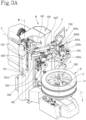
- the machine M comprises a frame 100 provided with a column 101 extending along a vertical direction W.
- the machine M also comprises a wheel-holder unit 200 on which the wheel R is placed when the tyre P needs to be mounted to the rim C.
- the wheel-holder unit 200 stands opposite the frame 100 on an extension of the frame 100 acting as a base.
- the wheel R is mounted on the wheel-holder unit 200 in such a way that the axis of rotation of the wheel R is positioned vertically, that is to say, in such a way that the wheel R has one sidewall facing towards the wheel-holder unit 200 (that is, towards the base of the machine M) and one sidewall facing in the opposite direction.
- the bead facing towards the wheel-holder unit 200 may be defined as "lower bead” of the tyre P and the opposite bead as “upper bead”.
- the annular edge of the rim C facing towards the wheel-holder unit 200 may be defined as “lower annular edge” and the opposite annular edge as "upper annular edge”.
- the wheel-holder unit 200 is movable in rotation about a vertical axis of rotation Y and is also movable in translation towards and away from the column 101 along a horizontal axis of translation X.
- the machine M comprises a lifting system 201 located in the proximity of the wheel-holder unit 200.
- the lifting system 201 comprises a supporting base 202 on which the wheel R can be rested and which is movable between a loading/unloading position, where it is inclined relative to the wheel-holder unit 200 so as to be used to all effects like a ramp on which the wheel R can be rested, and an unloading position, where it is positioned horizontally so that the wheel R resting on it can be pushed towards the wheel-holder unit 200.
- the machine M also comprises a mounting tool 301, configured to operatively engage the tyre P.
- the mounting tool 301 is configured to be inserted between the upper bead of the tyre P and an upper annular edge of the rim C while the tyre P is being mounted to the rim, as described in detail below.
- the mounting tool 301 is operatively connected to an operating head 300 that is slidably movable along the vertical direction W towards and away from the wheel R.
- the machine M comprises a supporting arm 800 that is connected to the column 101 which the mounting tool 301 is connected to in order to operatively engage the tyre P so as to mount the tyre to the rim C.
- the supporting arm 800 is movable along a direction parallel to the horizontal axis of translation X between an extracted position, where it places the mounting tool 301 close to the wheel to operate thereon, and a retracted position where it places the mounting tool 301 away from the wheel R.
- the machine M also comprises a demounting tool 302, configured to operatively engage the tyre P in order to demount the tyre from the rim C.
- the demounting tool 302 is operatively connected to the same supporting arm 800 which the mounting tool 301 is connected to. In this situation, the supporting arm 800 is rotatable about its direction of extension so as to confront the tyre P with the mounting tool 301 and the demounting tool 302 alternately.
- the machine M may also comprise a first and a second bead breaker disc 303a, 303b which are configured to operate on the tyre P when it is being demounted from the rim C. More specifically, the first bead breaker disc 303a separates the upper bead of the tyre P from the upper annular edge of the rim C and the second bead breaker disc 303b separates the lower bead of the tyre P from the lower annular edge of the rim C.
- the machine M also comprises a main arm 400, extending above the wheel-holder unit 200 between a first end 400a that is operatively connected to the column 101, and a second end 400b.
- the main arm 400 comprises a first segment 400' extending from the first end 400a of the main arm 400.
- the first segment 400' extends along a direction parallel to the horizontal axis of translation X of the wheel-holder unit 200.
- the main arm 400 also comprises a second segment 400" extending from the second end 400b of the main arm 400 and connected to the first segment 400' by a joint 401.
- the joint 401 is configured to allow adjusting the angular position of the second segment 400" relative to the first segment 400'.
- the joint 401 is made in the form of a hinge.
- the joint 401 may be made in any form that will allow adjusting the angular position of the second segment 400" relative to the first segment 400'.
- the joint 401 is operable manually by an operator slackening it to modify the angular position of the second segment 400" and then tightening it to lock the second segment 400" at that position.
- the joint 401 is operable automatically by a control unit of the machine M.
- the machine M also comprises a working unit 500 that is connected to the main arm 400 and includes a first arm 501a pivoted at a hinge point F to the second end 400b of the main arm 400 to rotate about the hinge point F itself.
- the hinge point F lies in a plane that includes the vertical axis of rotation Y and the horizontal axis of translation X of the wheel-holder unit 200.
- the working unit 500 also comprises a first sidewall pressing tool 502a connected to the first arm 501a and configured to come into abutment against a sidewall of the tyre P of the wheel R mounted on the wheel-holder unit 200.
- the first sidewall pressing tool 502a is made in the form of a roller that rotates freely about a horizontal axis.
- the first sidewall pressing tool 502a may be made in the form of a pressing device.
- the working unit 500 is movable along the vertical direction W between a working configuration, where it is close to the wheel-holder unit 200 and a rest configuration, where it is raised and distal from the wheel-holder unit 200.
- the first sidewall pressing tool 502a is engaged against the tyre P to keep the upper bead of the tyre P within the annular groove of the rim C, as will be described below.
- the working unit 500 is movable between the rest configuration thanks to a vertical translational movement of the main arm 400.
- the main arm 400 is movable vertically to move the working unit 500 between the working configuration and the rest configuration.
- the main arm 400 is operatively connected to the column 101 by a slide 102 which can be driven by an actuator slidably along the column 101.
- a sliding movement of the slide 102 corresponds to a vertical translational movement of the main arm 400, hence of the working unit 500, from the working configuration to the rest configuration and vice versa.
- the slide 102 is located on a side portion of the column 101 of the machine M so as not to hamper or endanger the operator during mounting operations.
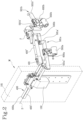
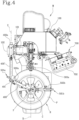
- the main arm 400 is movable by translation along a movement axis Z parallel to, and spaced from, the horizontal axis of translation X towards and away from the column 101 to keep the hinge point F vertically aligned with the vertical axis of rotation Y of the wheel-holder unit 200, responsive to a movement in translation of the wheel-holder unit 200 (arrow, Figure 4 ).
- the main arm 400 is made to move in translation along the movement axis Z towards and away from the column 101 so as to align the hinge point F vertically with the vertical axis of rotation Y of the wheel-holder unit 200 based on the position adopted by the latter after being moved in translation along the horizontal axis of translation X.
- the main arm 400 is made to move in translation parallel to the horizontal axis of translation X so as to adjust the position F of the hinge point relative to the position adopted by the vertical axis of rotation Y of the wheel-holder unit 200 after the latter has been moved in translation.
- the first segment 400' is housed in a specially shaped housing made in the slide 102 and is moved in and out of the housing by an actuator.
- the rim C is fastened to the wheel-holder unit 200 while the tyre P is rested thereon, ready to be fitted into the annular groove of the rim C.
- the main arm 400 moves in translation towards and away from the column 101 in order to bring the hinge point F into vertical alignment with the vertical axis of rotation Y of the wheel-holder unit 200 (that is to say, with the centre of the rim C).
- the first segment 400" is moved in and out of the housing so as to align the hinge point F with the centre of the rim C below.
- the first segment 400 is disposed parallel to the horizontal axis of translation X, while the second segment 400" is inclined at an angle such as to keep the hinge point vertically aligned with the vertical axis of rotation Y of the wheel-holder unit 200.
- the mounting tool 301 is inserted between the upper bead of the tyre P and the upper annular edge of the rim C.
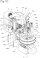
- the main arm 400 is moved down along the column 101 in order to move the working unit 500 from the rest configuration ( Figure 3A ) to the working configuration ( Figure 3B ).
- the first sidewall pressing tool 502a is engaged against the sidewall of the tyre P to press down on the upper bead.
- the wheel-holder unit 200 is set in rotation.
- the first sidewall pressing tool 502a since the first sidewall pressing tool 502a is engaged on the sidewall of the tyre P, it is entrained in rotation by the tyre P itself. This causes the first arm 501a to move freely in rotation about the hinge point F. That way, the first sidewall pressing tool 502a is one with the tyre P and operates thereon to hold down the upper bead.
- the main arm 400 When mounting is over, that is to say, when the whole of the upper bead has been inserted into the annular groove of the rim C, the main arm 400 is raised, causing the working unit 500 to pass from the working configuration to the rest configuration.
- the first arm 501a is also tiltable in a vertical plane between a lowered position, in which it keeps the first sidewall pressing tool 502a at a position where it confronts the wheel R, and a raised position, where it tilts the first sidewall pressing tool 502a away from the wheel R.
- the first arm 501a comprises a first portion 501a' which, in the working configuration, extends parallel to the vertical direction W.
- the first arm 501a also comprises a second portion 502a", oriented transversely to the first portion 501a' to define a shape substantially like that of a letter L.
- the first sidewall pressing tool 502a is mounted at a free end of the second portion 501a".
- the machine M comprises a slider 600a, engaged with the first sidewall pressing tool 502a and movable slidably along the second portion 501a" of the first arm 501a to adjust the position of the first sidewall pressing tool 502a, for example, according to the diameter of the wheel R.
- the working unit 500 also comprises a second arm 501b, provided with a second sidewall pressing tool 502b that is connected at an angularly fixed position to the second end 400b of the main arm 400 at the hinge point F.
- the second arm 501b too, has a first portion 501b' which runs parallel to the vertical direction W when the working unit 500 is in the working configuration, and a second portion 501b" which is oriented transversely to the first portion 501b'.
- the second arm 501b has a substantially L-shaped configuration in which the first sidewall pressing tool 502b is mounted at a free end of the second portion 501b".
- the second sidewall pressing tool 502b is also made in the form of a freely rotating roller with a substantially horizontal axis.
- the second sidewall pressing tool 502b may be made in the form of a disc.
- the machine M comprises a further slider 600b, engaged with the second sidewall pressing tool 502b and movable slidably along the second portion 501b" of the second arm 501b to adjust the position of the second sidewall pressing tool 502b, for example, according to the diameter of the wheel R.
- the first and the second sidewall pressing tools 502a, 502b are mounted on the respective sliders 600a, 600b in such a way that their respective axes of rotation are slightly convergent towards each other and towards the vertical axis of rotation Y of the wheel-holder unit 200. This inclination contributes to and facilitates the action of holding down the upper bead.
- the second arm 501b is tiltable in a vertical plane between a lowered position, where it keeps the second sidewall pressing tool 502b facing the wheel R, and a raised position, where the second sidewall pressing tool 502b is tilted away from the wheel R.
- the possibility of tilting the second arm 501b is particularly useful in that it allows using the second sidewall pressing tool 502b when the wheels R being handled are especially large, whilst the second sidewall pressing tool 502b can be placed at a rest position of non-interference when it is not needed, that is to say, when the wheels R involved are smaller and a single sidewall pressing tool is sufficient.
- first and the second sidewall pressing tools 502a, 502b are positioned at the same vertical height. More in detail, when the first and the second sidewall pressing tools 502a, 502b are both at the lowered position and the working unit 500 is in the working configuration, they are positioned at substantially the same height so that they both act on the sidewall of the tyre P.
- the vertical height of the first and second sidewall pressing tools 502a, 502b relative to the respective arms 501a, 501b can be adjusted.
- the second sidewall pressing tool 502b In use, therefore, when the second sidewall pressing tool 502b is not needed, it is moved to the lowered position.
- the working unit 500 is moved from the rest configuration to the working configuration so that the first and second sidewall pressing tools 502a, 502b are engaged on the sidewall of the tyre P.
- the wheel-holder unit 200 After that, the wheel-holder unit 200 is set in rotation. In this situation, the second sidewall pressing tool 502b is not entrained in rotation by the tyre P but remains at an angularly fixed position relative to the hinge point F.
- the first sidewall pressing tool 502a (together with the first arm 501a) is entrained in rotation by the tyre P, which is rotating about the hinge point F. In this situation, the first arm 501a stops rotating about the hinge point F just before the second arm 501b.
- the machine M also comprises a control console 700 for controlling and driving the machine during mounting operations.
- the control console 700 comprises a display 701 configured to show information relating to the process for mounting the tyre P, and a control desk 702 comprising a plurality of buttons and/or levers configured to allow manually controlling the main arm 400.
- buttons and/or levers can be used for manually controlling the tilting of the first and second arms 501a, 501b and/or for manually controlling the mounting tool 301.
- the control console 700 also comprises a supporting structure 703 extending between the display 701 and the control desk 702.
- the supporting structure 703 comprises a vertical central member 703a and a plurality of auxiliary members 703b extending away from the central member 703a in a horizontal direction and provided with tool compartments.
- the control console 700 is configured to receive input data representing the diameter size of a wheel R mounted on the wheel-holder unit 200 and to send this data to a control unit.
- the control unit is configured to receive the input data from the control console 700 and, based on this data, to send instructions to the main arm 400 as to how the main arm 400 must be positioned relative to the wheel-holder unit 200.
- control console 700 is also configured to move the mounting tool and/or other tools of the machine M.
- the machine M also comprises a supporting rod 800 having a first end 800a that is operatively connected to the control console 700 and a second end 800b that is hinged to the frame 100 to allow the supporting rod 800 to rotate with the control console 700.
- This aspect is particularly advantageous because it allows orienting the control console 700 according to the operator's position and/or according to the space in which the machine M is positioned.
- This aspect is also advantageous when the machine M has to be packed for transportation purposes.
- the supporting rod 800 is rotated in such a way that the control console 700 occupies the space between the wheel-holder unit 200 and the column 101.
- the machine M also comprises a locking device 900, for example, a clamp, used to prevent the supporting rod 800 from rotating. More specifically, the locking device 900 is used when the machine M is installed and does not need to be transported. In effect, the locking device 900 prevents the supporting rod 800 from rotating about the second end 800b when the machine M is in use.
- a locking device 900 for example, a clamp
- the locking device 900 does not, however, prevent the control console 700 from moving around the first end 800a of the control rod 800. More in detail, the control console 700 is applied to the first end 800a of the supporting rod 800 by means of an articulated joint S that is configured to allow the control console 700 to rotate about the articulated joint S even when the supporting rod 800 is locked by the locking device 900. In this situation, the control console 700 is free to rotate so that it can be suitably oriented according to the operator's needs and/or available space.
- an object of this invention is a method for mounting a tyre P of a vehicle wheel R relative to a corresponding rim C of the wheel R.
- the method comprises a step of preparing a machine M for mounting and demounting the tyre P relative to the rim C.
- the machine M includes a frame 100 provided with a column 101 that extends along a vertical direction W and a wheel-holder unit 200 that is movable in rotation about a vertical axis of rotation Y and in translation towards and away from the column 101 along a horizontal axis of translation X.
- the machine M also comprises a mounting tool 301, configured to operatively engage the tyre P so as to mount the tyre to the rim C.
- the machine M comprises a supporting arm 800 connected to the column 101 and configured to support the mounting tool 301.
- the machine M may comprise a demounting tool 302, configured to operatively engage the tyre P in order to demount the tyre from the rim C.
- the machine M also comprises a main arm 400, extending above the wheel-holder unit 200 between a first end 400a that is connected to the column 101, and a second end 400b.
- the machine M also comprises a working unit 500 that includes a first arm 501a pivoted at a hinge point F to the second end 400b of the main arm 400 to rotate about the hinge point F.
- the working unit 500 also comprises a first sidewall pressing tool 502a connected to the first arm 501a and configured to come into abutment against a sidewall of the tyre P of the wheel R mounted on the wheel-holder unit 200.
- the method also comprises a step of locking the rim C to the wheel-holder unit 200, for example, by means of a clamp.
- the method also comprises a step of placing a mounting tool 301 between an annular edge of the rim C and a bead of the tyre P.
- the method comprises a step of moving the main arm 400 in translation (parallel to the horizontal axis of translation X), towards and away from the column 101 in order to bring the hinge point F into vertical alignment with the vertical axis of rotation Y of the wheel-holder unit 200, that is to say, with the centre of the rim C.
- the main arm 400 is movable in translation along a movement axis Z parallel to the horizontal axis of translation X.
- the second arm 501a is tiltable in a vertical plane between a lowered position, where it keeps the first sidewall pressing tool 502a facing the wheel R, and a raised position, where the first sidewall pressing tool 502a is tilted away from the wheel R to prevent it from interfering with operations for locking and removing the rim C to and from the wheel-holder unit 200.
- the method may thus comprise a step of tilting in which the first arm 501a is brought to the lowered position, where it is then possible to operate on the wheel R.
- the method comprises a step of moving the working unit 500 along the vertical direction W from a rest configuration, where it is raised and distal from the wheel-holder unit 200 (hence from the wheel R), to a working configuration, where it is moved close to the wheel-holder unit 200 (hence to the wheel R) to bring the first sidewall pressing tool 502a into abutment against the tyre P.
- Passing from the rest configuration to the working configuration is accomplished through a step of moving the main arm 400 slidably along the column 101.
- the main arm 400 is made to move vertically in translation along the column 101 in such a way as to move the working unit 500 towards the wheel R to engage the first sidewall pressing tool 502a against the sidewall of the tyre P.
- the wheel-holder unit 200 is set in rotation.
- the first sidewall pressing tool 502a engaged against the tyre P, is entrained in rotation by the tyre P itself and rotates as one therewith while holding down the bead and acting in conjunction with the mounting tool 301 to mount the tyre P.
- the method also comprises a step of preparing a second sidewall pressing tool 502b connected to the main arm 400.
- the second sidewall pressing tool 502b is applied to a second arm 501b that is connected at an angularly fixed position to the second end 400b of the main arm 400 at the hinge point F.
- the second sidewall pressing tool 502b is engaged against the sidewall of the tyre P and acts in conjunction with the first sidewall pressing tool 502a to seat the upper bead of the tyre P onto the rim C.
- This invention achieves the preset aims and overcomes the disadvantages of the prior art.
- this invention provides a machine and a method that are reliable, easy to use and convenient.
- this invention provides a machine in which the articulated arm, at the start of operations to mount the tyre to the rim, is able to position the hinge point so it is vertically aligned with the wheel-holder unit at whatever position the wheel-holder unit has adopted after being moved in translation along the horizontal axis of translation.
Landscapes
- Engineering & Computer Science (AREA)
- Mechanical Engineering (AREA)
- Testing Of Balance (AREA)
- Tires In General (AREA)
- Automobile Manufacture Line, Endless Track Vehicle, Trailer (AREA)
Claims (15)
- Maschine (M) zur Montage und Demontage eines Reifens (P) relativ zu einer entsprechenden Felge (C) eines Fahrzeugrades (R), umfassend:- einen Rahmen (100), der mit einer Säule (101) versehen ist, die sich entlang einer vertikalen Richtung (W) erstreckt;- eine Radhaltereinheit (200), die rotatorisch um eine vertikale Drehachse (Y) und translatorisch zu der Säule (101) hinführend oder von ihr wegführend entlang einer horizontalen Translationsachse (X) bewegbar ist;- einen Tragarm (800), der mit der Säule (101) verbunden ist;- ein Montagewerkzeug (301), das mit dem Tragarm (800) verbunden und dazu ausgelegt ist, mit dem Reifen (P) betriebswirksam einzugreifen, um den Reifen an der Felge (C) zu montieren;- ein Demontagewerkzeug (302), das dazu ausgelegt ist, den Reifen (P) betriebswirksam einzugreifen, um den Reifen von der Felge (C) zu demontieren;- einen Hauptarm (400), der sich über der Radhaltereinheit (200) zwischen einem ersten Ende (400a), das mit der Säule (101) betriebswirksam verbunden ist, und einem zweiten Ende (400b) erstreckt;- eine Arbeitseinheit (500), die mit dem Hauptarm (400) verbunden ist und Folgendes einschließt:einen ersten Arm (501a), der in einem Gelenkpunkt (F) an dem zweiten Ende (400b) des Hauptarms (400) schwenkbar gelagert ist, um sich um den Gelenkpunkt (F) zu drehen, in dem der Gelenkpunkt (F) in einer Ebene liegt, die die vertikale Drehachse (Y) und die horizontale Translationsachse (X) einschließt, undein erstes Seitenwandpresswerkzeug (502a), das mit dem ersten Arm (501a) verbunden und so ausgelegt ist, dass es gegen eine Seitenwand des Reifens (P) des Rades (R) zur Anlage kommt, das auf der Radhaltereinheit (200) montiert ist,die Arbeitseinheit (500) ist entlang der vertikalen Richtung (W) zwischen einer Arbeitsauslegung, in der sie sich in der Nähe der Radhaltereinheit (200) befindet, und einer Ruheauslegung, in der sie angehoben und von der Radhaltereinheit (200) distal ist, bewegbar,wobei die Maschine dadurch gekennzeichnet ist, dass der Hauptarm (400) durch Translation entlang einer Bewegungsachse (Z) parallel zu und beabstandet von der horizontalen Translationsachse (X) zu der Säule (101) hinführend oder von ihr wegführend bewegbar ist, um den Gelenkpunkt (F) vertikal auf die vertikale Drehachse (Y) der Radhaltereinheit (200) ausgerichtet zu behalten, als Reaktion auf eine translatorische Bewegung der Radhaltereinheit (200).
- Maschine nach Anspruch 1, wobei der Hauptarm (400) vertikal bewegbar ist, um die Arbeitseinheit (500) zwischen der Arbeitsauslegung und der Ruheauslegung zu bewegen.
- Maschine nach Anspruch 1 oder 2, wobei der erste Arm (501a) in einer vertikalen Ebene zwischen einer abgesenkten Position, in der er das erste Seitenwandpresswerkzeug (502a) dem Rad (R) zugewandt behält, und einer angehobenen Position kippbar ist, in der das erste Seitenwandpresswerkzeug (502a) von dem Rad (R) wegführend gekippt ist.
- Maschine nach einem der vorhergehenden Ansprüche, wobei der erste Arm (501a) einen ersten Abschnitt (501a') und einen zweiten Abschnitt (502a") umfasst, der quer zu dem ersten Abschnitt (501a') orientiert ist, um eine Form wie die eines Buchstabens L zu definieren, wobei das erste Seitenwandpresswerkzeug (502a) an einem freien Ende des zweiten Abschnitts (501a") montiert ist, und wobei sich der erste Abschnitt (501a'), wenn er sich in der Arbeitsauslegung befindet, parallel zu der vertikalen Richtung (W) erstreckt.
- Maschine nach Anspruch 4, umfassend einen Schieber (600a), der mit dem ersten Seitenwandpresswerkzeug (502a) in Eingriff steht und verschiebbar entlang des zweiten Abschnitts (501a") des ersten Arms (501a) bewegbar ist, um die Position des ersten Seitenwandpresswerkzeugs (502a) einzustellen.
- Maschine nach einem der vorhergehenden Ansprüche, wobei die Arbeitseinheit (500) einen zweiten Arm (501b) umfasst, der mit einem zweiten Seitenwandpresswerkzeug (502b) versehen ist, das an einer winkelmäßig festen Position mit dem zweiten Ende (400b) des Hauptarms (400) an dem Gelenkpunkt (F) verbunden ist.
- Maschine nach Anspruch 6, wobei eine oder beide der folgenden Bedingungen erfüllt sind:i) die Maschine umfasst einen weiteren Schieber (600b), der mit dem zweiten Seitenwandpresswerkzeug (502b) in Eingriff steht und verschiebbar entlang des zweiten Arms (501b) bewegbar ist, um die Position des zweiten Seitenwandpresswerkzeugs (502b) einzustellen;ii) das erste und das zweite Seitenwandpresswerkzeug (502a, 502b) sind auf der gleichen vertikalen Höhe positioniert.
- Maschine nach einem der vorhergehenden Ansprüche, wobei der Hauptarm (400) ein erstes Segment (400'), das sich von dem ersten Ende (400a) des Hauptarms (400) erstreckt, und ein zweites Segment (400"), das sich von dem zweiten Ende (400b) des Hauptarms (400) erstreckt und mit dem ersten Segment (400') durch eine Kupplung (401) verbunden ist, die ausgelegt ist, um die Einstellung der Winkelposition des zweiten Segments (400") relativ zu dem ersten Segment (400') zu ermöglichen, umfasst.
- Maschine nach einem der Ansprüche 6 bis 8, wobei das zweite Seitenwandpresswerkzeug (502b) in Form einer Rolle ausgebildet ist, die sich frei um eine horizontale Achse dreht.
- Maschine nach einem der vorhergehenden Ansprüche, umfassend:- eine Steuerkonsole (700), die ausgelegt ist, um Eingabedaten zu empfangen, die die Durchmessergröße eines Rads (R) darstellen, das an der Radhaltereinheit (200) montiert ist;- eine Steuereinheit, die ausgelegt ist, um die Eingabedaten von der Steuerkonsole (700) zu empfangen und basierend auf diesen Daten Anweisungen an den Hauptarm (400) zu senden, wie der Hauptarm (400) relativ zur Radhaltereinheit (200) positioniert werden muss.
- Maschine nach Anspruch 10, umfassend eine Tragstange (800) mit einem ersten Ende (800a), das mit der Steuerkonsole (700) betriebswirksam verbunden ist, und einem zweiten Ende (800b), das an dem Rahmen (100) der Maschine (M) angelenkt ist, um zu ermöglichen, dass sich die Tragstange (800) mit der Steuerkonsole (700) dreht, wobei die Maschine (M) ferner eine Verriegelungsvorrichtung (900) umfasst, die verwendet wird, um zu verhindern, dass sich die Tragstange (800) dreht.
- Maschine nach Anspruch 11, wobei die Steuerkonsole (700) an dem ersten Ende (800a) der Tragstange (800) mittels einer Gelenkkupplung (S) angebracht ist, das ausgelegt ist, um es der Steuerkonsole (700) zu ermöglichen, sich um die Gelenkkupplung (S) zu drehen.
- Maschine nach einem der Ansprüche 10 bis 12, wobei die Steuerkonsole (700) Folgendes umfasst:- eine Anzeige (701), die ausgelegt ist, um Informationen in Bezug auf den Prozess zur Montage oder Demontage des Reifens (P) anzuzeigen;- ein Steuerpult (702), das eine Vielzahl von Tasten und/oder Hebeln umfasst, die ausgelegt sind, um eine manuelle Steuerung des Hauptarms (400) und/oder eine manuelle Steuerung des Montagewerkzeugs (301) zu ermöglichen;- eine Tragstruktur (703), die sich zwischen der Anzeige (701) und dem Steuerpult (702) erstreckt, wobei die Tragstruktur (703) ein vertikales zentrales Element (703a) und eine Vielzahl von Hilfselementen (703b) umfasst, die sich von dem zentralen Element (703a) wegführend in einer horizontalen Richtung erstrecken und mit Werkzeugunterteilungen versehen sind.
- Verfahren zur Montage eines Reifens (P) eines Fahrzeugrades (R) relativ zu einer entsprechenden Felge (C) des Rades (R), umfassend die folgenden Schritte:- Vorbereiten einer Maschine (M) zur Montage des Reifens (P) relativ zur Felge (C) und einschließend:einen Rahmen (100), der mit einer Säule (101) versehen ist, die sich entlang einer vertikalen Richtung (W) erstreckt,eine Radhaltereinheit (200), die rotatorisch um eine vertikale Drehachse (Y) und translatorisch zu der Säule (101) hinführend oder von ihr wegführend entlang einer horizontalen Translationsachse (X) bewegbar ist,ein Montagewerkzeug (301), das dazu ausgelegt ist, den Reifen (P) betriebswirksam einzugreifen,einen Hauptarm (400), der sich über der Radhaltereinheit (200) zwischen einem ersten Ende (400a), das mit der Säule (101) verbunden ist, und einem zweiten Ende (400b) erstreckt,eine Arbeitseinheit (500), die einen ersten Arm (501a) einschließt, der an dem zweiten Ende (400b) des Hauptarms (400) an einem Gelenkpunkt (F) schwenkbar gelagert ist, um sich um den Gelenkpunkt (F) zu drehen, und ein erstes Seitenwandpresswerkzeug (502a), das ausgelegt ist, um gegen eine Seitenwand des Reifens (P) des auf der Radhaltereinheit (200) montierten Rades (R) zur Anlage zu kommen und das mit dem ersten Arm (501a) verbunden ist,wobei das Verfahren die folgenden Schritte umfasst:- Verriegeln der Felge (C) an der Radhaltereinheit (200);- Bewegen der Radhaltereinheit (200) translatorisch entlang der horizontalen Translationsachse (X);- Bewegen der Arbeitseinheit (500) entlang der vertikalen Richtung (Y) von einer Ruheauslegung, in der sie angehoben und distal von dem Rad (R) ist, zu einer Arbeitsauslegung, in der sie nahe an das Rad (R) bewegt wird, um das erste Seitenwandpresswerkzeug (501a) zur Anlage gegen die Seitenwand des Reifens (P) zu bringen;- Platzieren eines Montagewerkzeugs (301) zwischen einer ringförmigen Kante der Felge (C) und einem Wulst des Reifens (P);- Drehen der Radhaltereinheit (200),wobei das Verfahren dadurch gekennzeichnet ist, dass es ferner einen Schritt zum translatorischen Bewegen des Hauptarms (400) entlang einer Bewegungsachse (Z), parallel zur horizontalen Translationsachse (X) und davon beabstandet, zu der Säule (101) hinführend oder von ihr wegführend umfasst, so dass der Gelenkpunkt (F) mit der vertikalen Drehachse (Y) der Radhaltereinheit (200) ausgerichtet bleibt.
- Verfahren nach Anspruch 14, wobei eine oder beide der folgenden Bedingungen erfüllt sind:i) das Verfahren einen Schritt zum Kippen des ersten Seitenwandpresswerkzeugs (501a) durch Drehung um eine horizontale Achse umfasst;ii) das Verfahren einen Schritt zum Vorbereiten eines zweiten Seitenwandpresswerkzeugs (502b) umfasst, das mit dem Hauptarm (400) verbunden ist, wobei, wenn sich der Hauptarm (400) in der Arbeitsauslegung befindet, das zweite Seitenwandpresswerkzeug (502b) in Kontakt mit der Seitenwand des Reifens (P) an einem Punkt ist, der relativ zu der Drehung des Rads (R) stationär ist.
Applications Claiming Priority (1)
| Application Number | Priority Date | Filing Date | Title |
|---|---|---|---|
| IT102021000026960A IT202100026960A1 (it) | 2021-10-20 | 2021-10-20 | Macchina per il montaggio e lo smontaggio di uno pneumatico rispetto ad un corrispondente cerchione di una ruota di un veicolo e metodo per montare uno pneumatico |
Publications (2)
| Publication Number | Publication Date |
|---|---|
| EP4169743A1 EP4169743A1 (de) | 2023-04-26 |
| EP4169743B1 true EP4169743B1 (de) | 2024-06-12 |
Family
ID=79018436
Family Applications (1)
| Application Number | Title | Priority Date | Filing Date |
|---|---|---|---|
| EP22202443.2A Active EP4169743B1 (de) | 2021-10-20 | 2022-10-19 | Maschine zur montage und demontage eines reifens relativ zu einer entsprechenden fahrzeugradfelge und verfahren zur montage eines reifens |
Country Status (5)
| Country | Link |
|---|---|
| US (1) | US12594797B2 (de) |
| EP (1) | EP4169743B1 (de) |
| CN (1) | CN115991065A (de) |
| ES (1) | ES2987432T3 (de) |
| IT (1) | IT202100026960A1 (de) |
Families Citing this family (1)
| Publication number | Priority date | Publication date | Assignee | Title |
|---|---|---|---|---|
| CN114919344A (zh) * | 2022-06-09 | 2022-08-19 | 营口辽南德威机械设备有限公司 | 一种有双面工具头并带有翻转结构的立式轮胎拆装机 |
Family Cites Families (13)
| Publication number | Priority date | Publication date | Assignee | Title |
|---|---|---|---|---|
| DE3835536A1 (de) | 1988-10-19 | 1990-04-26 | Scholze Erich Gmbh Co Kg | Einrichtung zum festklemmen eines kettbaumrohres od. dgl. |
| AU667674B2 (en) * | 1991-09-11 | 1996-04-04 | Bandag Licensing Corporation | Tire buffing apparatus |
| US6182736B1 (en) * | 1998-06-15 | 2001-02-06 | Hennessy Industries, Inc. | Helper arm for a rim holding tire changer |
| JP4395624B2 (ja) * | 2000-09-28 | 2010-01-13 | 株式会社バンザイ | タイヤ着脱装置 |
| US7438109B2 (en) * | 2005-12-30 | 2008-10-21 | Hennessy Industries, Inc. | Tire changer |
| ITMC20060115A1 (it) | 2006-09-11 | 2008-03-12 | Societa Italiana Costruzioni Elettromeccaniche | Dispositivo perfezionato per macchine smontagomme, atto ad agevolare il montaggio del pneumatico senza sottoporlo ad eccessivo stiramento. |
| US8387675B1 (en) * | 2009-09-09 | 2013-03-05 | Hunter Engineering Company | Tire changing machine with automated tire bead pressing devices, controls and methods |
| JP5563742B2 (ja) * | 2008-03-19 | 2014-07-30 | 小野谷機工株式会社 | タイヤ着脱装置のマウントプレス装置 |
| EP2361791B1 (de) * | 2010-02-17 | 2013-06-05 | Snap-on Equipment Srl a unico socio | Démonte-pneu et procédé de mesure des variations de force agissant entre la surface périphérique d'un ensemble roue/pneu et d'un roulement |
| EP2962876B8 (de) * | 2014-07-03 | 2017-04-19 | CORGHI S.p.A. | Maschine und verfahren zum aufziehen und abnehmen eines reifens |
| CN105109288B (zh) * | 2015-09-11 | 2017-03-01 | 营口光明科技有限公司 | 一种轮胎拆装机助手 |
| CN106183665B (zh) * | 2016-08-26 | 2019-04-02 | 营口辽南德威机械设备有限公司 | 一种轮胎拆装机 |
| IT201800010722A1 (it) * | 2018-11-30 | 2020-05-30 | Nexion Spa | Apparato smontagomme |
-
2021
- 2021-10-20 IT IT102021000026960A patent/IT202100026960A1/it unknown
-
2022
- 2022-10-19 US US18/047,702 patent/US12594797B2/en active Active
- 2022-10-19 EP EP22202443.2A patent/EP4169743B1/de active Active
- 2022-10-19 ES ES22202443T patent/ES2987432T3/es active Active
- 2022-10-20 CN CN202211289280.3A patent/CN115991065A/zh active Pending
Also Published As
| Publication number | Publication date |
|---|---|
| US12594797B2 (en) | 2026-04-07 |
| IT202100026960A1 (it) | 2023-04-20 |
| EP4169743A1 (de) | 2023-04-26 |
| CN115991065A (zh) | 2023-04-21 |
| US20230118720A1 (en) | 2023-04-20 |
| ES2987432T3 (es) | 2024-11-14 |
Similar Documents
| Publication | Publication Date | Title |
|---|---|---|
| CN1935540B (zh) | 用于自动向轮辋装配轮胎和从轮辋拆卸轮胎的工具 | |
| EP2629992B1 (de) | Reifendemontiermaschine | |
| US6619362B2 (en) | Automatic tyre removal and mounting device and tyre removal machines equipped therewith | |
| US6056034A (en) | Difficult to mount tire changer and method for handling thereof | |
| US8905112B2 (en) | Device for demounting the second bead of a tire from a rim and respective demounting method | |
| JP2003182329A (ja) | タイヤ着脱装置のビード取りはずし用ヘッド | |
| EP4169744B1 (de) | Maschine zur montage und demontage eines reifens in bezug auf eine entsprechende felge und radwartungsverfahren | |
| US6588478B2 (en) | Tire removal machine | |
| EP4169743A1 (de) | Maschine zur montage und demontage eines reifens relativ zu einer entsprechenden fahrzeugradfelge und verfahren zur montage eines reifens | |
| US8869864B2 (en) | Machine for fitting and removing wheel tires for vehicles | |
| US20250033423A1 (en) | Tire changer apparatus | |
| US9944136B2 (en) | Machine for removing and fitting wheel tyres for vehicles | |
| US7946016B2 (en) | Method and machine for removing a tyre fitted with a rigid inner run-flat ring | |
| US4293020A (en) | Tire changing apparatus | |
| US5458177A (en) | Machine for mounting tires on wheel rims | |
| ES2924840T3 (es) | Aparato para cambiar neumáticos | |
| EP0659597B1 (de) | Vorrichtung zur Erleichterung des Demontierens und Montierens von Reifen auf und von Radfelgen | |
| JPH02231280A (ja) | ドア位置決め搬送台車 | |
| US6305453B1 (en) | Tire bead breaker | |
| US11813901B2 (en) | Device for clamping a rim of a vehicle wheel | |
| US20120138239A1 (en) | Bead detaching arm, tire demounting method and apparatus using bead detaching arm | |
| US4327794A (en) | Tire changing apparatus | |
| US2653653A (en) | Circumferentially adjustable tire removing device | |
| JPH06246628A (ja) | 平面研削盤における砥石自動交換装置 | |
| US9827817B2 (en) | Tire changing machine |
Legal Events
| Date | Code | Title | Description |
|---|---|---|---|
| PUAI | Public reference made under article 153(3) epc to a published international application that has entered the european phase |
Free format text: ORIGINAL CODE: 0009012 |
|
| STAA | Information on the status of an ep patent application or granted ep patent |
Free format text: STATUS: THE APPLICATION HAS BEEN PUBLISHED |
|
| AK | Designated contracting states |
Kind code of ref document: A1 Designated state(s): AL AT BE BG CH CY CZ DE DK EE ES FI FR GB GR HR HU IE IS IT LI LT LU LV MC ME MK MT NL NO PL PT RO RS SE SI SK SM TR |
|
| STAA | Information on the status of an ep patent application or granted ep patent |
Free format text: STATUS: REQUEST FOR EXAMINATION WAS MADE |
|
| 17P | Request for examination filed |
Effective date: 20231024 |
|
| RBV | Designated contracting states (corrected) |
Designated state(s): AL AT BE BG CH CY CZ DE DK EE ES FI FR GB GR HR HU IE IS IT LI LT LU LV MC ME MK MT NL NO PL PT RO RS SE SI SK SM TR |
|
| GRAP | Despatch of communication of intention to grant a patent |
Free format text: ORIGINAL CODE: EPIDOSNIGR1 |
|
| STAA | Information on the status of an ep patent application or granted ep patent |
Free format text: STATUS: GRANT OF PATENT IS INTENDED |
|
| INTG | Intention to grant announced |
Effective date: 20240108 |
|
| RAP3 | Party data changed (applicant data changed or rights of an application transferred) |
Owner name: NEXION S.P.A. |
|
| GRAS | Grant fee paid |
Free format text: ORIGINAL CODE: EPIDOSNIGR3 |
|
| GRAA | (expected) grant |
Free format text: ORIGINAL CODE: 0009210 |
|
| STAA | Information on the status of an ep patent application or granted ep patent |
Free format text: STATUS: THE PATENT HAS BEEN GRANTED |
|
| P01 | Opt-out of the competence of the unified patent court (upc) registered |
Effective date: 20240430 |
|
| AK | Designated contracting states |
Kind code of ref document: B1 Designated state(s): AL AT BE BG CH CY CZ DE DK EE ES FI FR GB GR HR HU IE IS IT LI LT LU LV MC ME MK MT NL NO PL PT RO RS SE SI SK SM TR |
|
| REG | Reference to a national code |
Ref country code: GB Ref legal event code: FG4D |
|
| REG | Reference to a national code |
Ref country code: CH Ref legal event code: EP |
|
| REG | Reference to a national code |
Ref country code: DE Ref legal event code: R096 Ref document number: 602022003926 Country of ref document: DE |
|
| REG | Reference to a national code |
Ref country code: IE Ref legal event code: FG4D |
|
| PG25 | Lapsed in a contracting state [announced via postgrant information from national office to epo] |
Ref country code: BG Free format text: LAPSE BECAUSE OF FAILURE TO SUBMIT A TRANSLATION OF THE DESCRIPTION OR TO PAY THE FEE WITHIN THE PRESCRIBED TIME-LIMIT Effective date: 20240612 |
|
| PG25 | Lapsed in a contracting state [announced via postgrant information from national office to epo] |
Ref country code: FI Free format text: LAPSE BECAUSE OF FAILURE TO SUBMIT A TRANSLATION OF THE DESCRIPTION OR TO PAY THE FEE WITHIN THE PRESCRIBED TIME-LIMIT Effective date: 20240612 Ref country code: HR Free format text: LAPSE BECAUSE OF FAILURE TO SUBMIT A TRANSLATION OF THE DESCRIPTION OR TO PAY THE FEE WITHIN THE PRESCRIBED TIME-LIMIT Effective date: 20240612 |
|
| REG | Reference to a national code |
Ref country code: LT Ref legal event code: MG9D |
|
| PG25 | Lapsed in a contracting state [announced via postgrant information from national office to epo] |
Ref country code: GR Free format text: LAPSE BECAUSE OF FAILURE TO SUBMIT A TRANSLATION OF THE DESCRIPTION OR TO PAY THE FEE WITHIN THE PRESCRIBED TIME-LIMIT Effective date: 20240913 |
|
| REG | Reference to a national code |
Ref country code: NL Ref legal event code: MP Effective date: 20240612 |
|
| PG25 | Lapsed in a contracting state [announced via postgrant information from national office to epo] |
Ref country code: LV Free format text: LAPSE BECAUSE OF FAILURE TO SUBMIT A TRANSLATION OF THE DESCRIPTION OR TO PAY THE FEE WITHIN THE PRESCRIBED TIME-LIMIT Effective date: 20240612 |
|
| PG25 | Lapsed in a contracting state [announced via postgrant information from national office to epo] |
Ref country code: NO Free format text: LAPSE BECAUSE OF FAILURE TO SUBMIT A TRANSLATION OF THE DESCRIPTION OR TO PAY THE FEE WITHIN THE PRESCRIBED TIME-LIMIT Effective date: 20240912 Ref country code: LV Free format text: LAPSE BECAUSE OF FAILURE TO SUBMIT A TRANSLATION OF THE DESCRIPTION OR TO PAY THE FEE WITHIN THE PRESCRIBED TIME-LIMIT Effective date: 20240612 Ref country code: HR Free format text: LAPSE BECAUSE OF FAILURE TO SUBMIT A TRANSLATION OF THE DESCRIPTION OR TO PAY THE FEE WITHIN THE PRESCRIBED TIME-LIMIT Effective date: 20240612 Ref country code: GR Free format text: LAPSE BECAUSE OF FAILURE TO SUBMIT A TRANSLATION OF THE DESCRIPTION OR TO PAY THE FEE WITHIN THE PRESCRIBED TIME-LIMIT Effective date: 20240913 Ref country code: FI Free format text: LAPSE BECAUSE OF FAILURE TO SUBMIT A TRANSLATION OF THE DESCRIPTION OR TO PAY THE FEE WITHIN THE PRESCRIBED TIME-LIMIT Effective date: 20240612 Ref country code: BG Free format text: LAPSE BECAUSE OF FAILURE TO SUBMIT A TRANSLATION OF THE DESCRIPTION OR TO PAY THE FEE WITHIN THE PRESCRIBED TIME-LIMIT Effective date: 20240612 Ref country code: RS Free format text: LAPSE BECAUSE OF FAILURE TO SUBMIT A TRANSLATION OF THE DESCRIPTION OR TO PAY THE FEE WITHIN THE PRESCRIBED TIME-LIMIT Effective date: 20240912 |
|
| REG | Reference to a national code |
Ref country code: ES Ref legal event code: FG2A Ref document number: 2987432 Country of ref document: ES Kind code of ref document: T3 Effective date: 20241114 |
|
| PG25 | Lapsed in a contracting state [announced via postgrant information from national office to epo] |
Ref country code: NL Free format text: LAPSE BECAUSE OF FAILURE TO SUBMIT A TRANSLATION OF THE DESCRIPTION OR TO PAY THE FEE WITHIN THE PRESCRIBED TIME-LIMIT Effective date: 20240612 |
|
| REG | Reference to a national code |
Ref country code: AT Ref legal event code: MK05 Ref document number: 1693930 Country of ref document: AT Kind code of ref document: T Effective date: 20240612 |
|
| PG25 | Lapsed in a contracting state [announced via postgrant information from national office to epo] |
Ref country code: NL Free format text: LAPSE BECAUSE OF FAILURE TO SUBMIT A TRANSLATION OF THE DESCRIPTION OR TO PAY THE FEE WITHIN THE PRESCRIBED TIME-LIMIT Effective date: 20240612 |
|
| PG25 | Lapsed in a contracting state [announced via postgrant information from national office to epo] |
Ref country code: PT Free format text: LAPSE BECAUSE OF FAILURE TO SUBMIT A TRANSLATION OF THE DESCRIPTION OR TO PAY THE FEE WITHIN THE PRESCRIBED TIME-LIMIT Effective date: 20241014 |
|
| PG25 | Lapsed in a contracting state [announced via postgrant information from national office to epo] |
Ref country code: PT Free format text: LAPSE BECAUSE OF FAILURE TO SUBMIT A TRANSLATION OF THE DESCRIPTION OR TO PAY THE FEE WITHIN THE PRESCRIBED TIME-LIMIT Effective date: 20241014 |
|
| PG25 | Lapsed in a contracting state [announced via postgrant information from national office to epo] |
Ref country code: PL Free format text: LAPSE BECAUSE OF FAILURE TO SUBMIT A TRANSLATION OF THE DESCRIPTION OR TO PAY THE FEE WITHIN THE PRESCRIBED TIME-LIMIT Effective date: 20240612 |
|
| PG25 | Lapsed in a contracting state [announced via postgrant information from national office to epo] |
Ref country code: EE Free format text: LAPSE BECAUSE OF FAILURE TO SUBMIT A TRANSLATION OF THE DESCRIPTION OR TO PAY THE FEE WITHIN THE PRESCRIBED TIME-LIMIT Effective date: 20240612 |
|
| PG25 | Lapsed in a contracting state [announced via postgrant information from national office to epo] |
Ref country code: IS Free format text: LAPSE BECAUSE OF FAILURE TO SUBMIT A TRANSLATION OF THE DESCRIPTION OR TO PAY THE FEE WITHIN THE PRESCRIBED TIME-LIMIT Effective date: 20241012 Ref country code: AT Free format text: LAPSE BECAUSE OF FAILURE TO SUBMIT A TRANSLATION OF THE DESCRIPTION OR TO PAY THE FEE WITHIN THE PRESCRIBED TIME-LIMIT Effective date: 20240612 |
|
| PG25 | Lapsed in a contracting state [announced via postgrant information from national office to epo] |
Ref country code: CZ Free format text: LAPSE BECAUSE OF FAILURE TO SUBMIT A TRANSLATION OF THE DESCRIPTION OR TO PAY THE FEE WITHIN THE PRESCRIBED TIME-LIMIT Effective date: 20240612 |
|
| PG25 | Lapsed in a contracting state [announced via postgrant information from national office to epo] |
Ref country code: RO Free format text: LAPSE BECAUSE OF FAILURE TO SUBMIT A TRANSLATION OF THE DESCRIPTION OR TO PAY THE FEE WITHIN THE PRESCRIBED TIME-LIMIT Effective date: 20240612 Ref country code: SK Free format text: LAPSE BECAUSE OF FAILURE TO SUBMIT A TRANSLATION OF THE DESCRIPTION OR TO PAY THE FEE WITHIN THE PRESCRIBED TIME-LIMIT Effective date: 20240612 |
|
| PG25 | Lapsed in a contracting state [announced via postgrant information from national office to epo] |
Ref country code: SM Free format text: LAPSE BECAUSE OF FAILURE TO SUBMIT A TRANSLATION OF THE DESCRIPTION OR TO PAY THE FEE WITHIN THE PRESCRIBED TIME-LIMIT Effective date: 20240612 |
|
| PG25 | Lapsed in a contracting state [announced via postgrant information from national office to epo] |
Ref country code: SM Free format text: LAPSE BECAUSE OF FAILURE TO SUBMIT A TRANSLATION OF THE DESCRIPTION OR TO PAY THE FEE WITHIN THE PRESCRIBED TIME-LIMIT Effective date: 20240612 Ref country code: SK Free format text: LAPSE BECAUSE OF FAILURE TO SUBMIT A TRANSLATION OF THE DESCRIPTION OR TO PAY THE FEE WITHIN THE PRESCRIBED TIME-LIMIT Effective date: 20240612 Ref country code: RO Free format text: LAPSE BECAUSE OF FAILURE TO SUBMIT A TRANSLATION OF THE DESCRIPTION OR TO PAY THE FEE WITHIN THE PRESCRIBED TIME-LIMIT Effective date: 20240612 Ref country code: PL Free format text: LAPSE BECAUSE OF FAILURE TO SUBMIT A TRANSLATION OF THE DESCRIPTION OR TO PAY THE FEE WITHIN THE PRESCRIBED TIME-LIMIT Effective date: 20240612 Ref country code: IS Free format text: LAPSE BECAUSE OF FAILURE TO SUBMIT A TRANSLATION OF THE DESCRIPTION OR TO PAY THE FEE WITHIN THE PRESCRIBED TIME-LIMIT Effective date: 20241012 Ref country code: EE Free format text: LAPSE BECAUSE OF FAILURE TO SUBMIT A TRANSLATION OF THE DESCRIPTION OR TO PAY THE FEE WITHIN THE PRESCRIBED TIME-LIMIT Effective date: 20240612 Ref country code: CZ Free format text: LAPSE BECAUSE OF FAILURE TO SUBMIT A TRANSLATION OF THE DESCRIPTION OR TO PAY THE FEE WITHIN THE PRESCRIBED TIME-LIMIT Effective date: 20240612 Ref country code: AT Free format text: LAPSE BECAUSE OF FAILURE TO SUBMIT A TRANSLATION OF THE DESCRIPTION OR TO PAY THE FEE WITHIN THE PRESCRIBED TIME-LIMIT Effective date: 20240612 |
|
| REG | Reference to a national code |
Ref country code: DE Ref legal event code: R097 Ref document number: 602022003926 Country of ref document: DE |
|
| PG25 | Lapsed in a contracting state [announced via postgrant information from national office to epo] |
Ref country code: DK Free format text: LAPSE BECAUSE OF FAILURE TO SUBMIT A TRANSLATION OF THE DESCRIPTION OR TO PAY THE FEE WITHIN THE PRESCRIBED TIME-LIMIT Effective date: 20240612 |
|
| PLBE | No opposition filed within time limit |
Free format text: ORIGINAL CODE: 0009261 |
|
| STAA | Information on the status of an ep patent application or granted ep patent |
Free format text: STATUS: NO OPPOSITION FILED WITHIN TIME LIMIT |
|
| 26N | No opposition filed |
Effective date: 20250313 |
|
| PG25 | Lapsed in a contracting state [announced via postgrant information from national office to epo] |
Ref country code: MC Free format text: LAPSE BECAUSE OF FAILURE TO SUBMIT A TRANSLATION OF THE DESCRIPTION OR TO PAY THE FEE WITHIN THE PRESCRIBED TIME-LIMIT Effective date: 20240612 |
|
| PG25 | Lapsed in a contracting state [announced via postgrant information from national office to epo] |
Ref country code: LU Free format text: LAPSE BECAUSE OF NON-PAYMENT OF DUE FEES Effective date: 20241019 Ref country code: BE Free format text: LAPSE BECAUSE OF NON-PAYMENT OF DUE FEES Effective date: 20241031 |
|
| REG | Reference to a national code |
Ref country code: BE Ref legal event code: MM Effective date: 20241031 |
|
| PG25 | Lapsed in a contracting state [announced via postgrant information from national office to epo] |
Ref country code: SE Free format text: LAPSE BECAUSE OF FAILURE TO SUBMIT A TRANSLATION OF THE DESCRIPTION OR TO PAY THE FEE WITHIN THE PRESCRIBED TIME-LIMIT Effective date: 20240612 |
|
| PG25 | Lapsed in a contracting state [announced via postgrant information from national office to epo] |
Ref country code: IE Free format text: LAPSE BECAUSE OF NON-PAYMENT OF DUE FEES Effective date: 20241019 |
|
| PGFP | Annual fee paid to national office [announced via postgrant information from national office to epo] |
Ref country code: DE Payment date: 20251028 Year of fee payment: 4 |
|
| PGFP | Annual fee paid to national office [announced via postgrant information from national office to epo] |
Ref country code: IT Payment date: 20251031 Year of fee payment: 4 |
|
| PGFP | Annual fee paid to national office [announced via postgrant information from national office to epo] |
Ref country code: FR Payment date: 20251027 Year of fee payment: 4 |
|
| PG25 | Lapsed in a contracting state [announced via postgrant information from national office to epo] |
Ref country code: CY Free format text: LAPSE BECAUSE OF FAILURE TO SUBMIT A TRANSLATION OF THE DESCRIPTION OR TO PAY THE FEE WITHIN THE PRESCRIBED TIME-LIMIT; INVALID AB INITIO Effective date: 20221019 |
|
| PGFP | Annual fee paid to national office [announced via postgrant information from national office to epo] |
Ref country code: ES Payment date: 20251118 Year of fee payment: 4 |
|
| PG25 | Lapsed in a contracting state [announced via postgrant information from national office to epo] |
Ref country code: HU Free format text: LAPSE BECAUSE OF FAILURE TO SUBMIT A TRANSLATION OF THE DESCRIPTION OR TO PAY THE FEE WITHIN THE PRESCRIBED TIME-LIMIT; INVALID AB INITIO Effective date: 20221019 |
|
| REG | Reference to a national code |
Ref country code: CH Ref legal event code: H13 Free format text: ST27 STATUS EVENT CODE: U-0-0-H10-H13 (AS PROVIDED BY THE NATIONAL OFFICE) Effective date: 20260527 |
|
| PG25 | Lapsed in a contracting state [announced via postgrant information from national office to epo] |
Ref country code: TR Free format text: LAPSE BECAUSE OF FAILURE TO SUBMIT A TRANSLATION OF THE DESCRIPTION OR TO PAY THE FEE WITHIN THE PRESCRIBED TIME-LIMIT Effective date: 20240612 |
|
| PG25 | Lapsed in a contracting state [announced via postgrant information from national office to epo] |
Ref country code: SI Free format text: LAPSE BECAUSE OF FAILURE TO SUBMIT A TRANSLATION OF THE DESCRIPTION OR TO PAY THE FEE WITHIN THE PRESCRIBED TIME-LIMIT Effective date: 20240612 |
|
| PG25 | Lapsed in a contracting state [announced via postgrant information from national office to epo] |
Ref country code: LT Free format text: LAPSE BECAUSE OF FAILURE TO SUBMIT A TRANSLATION OF THE DESCRIPTION OR TO PAY THE FEE WITHIN THE PRESCRIBED TIME-LIMIT Effective date: 20240612 |
|
| PG25 | Lapsed in a contracting state [announced via postgrant information from national office to epo] |
Ref country code: CH Free format text: LAPSE BECAUSE OF NON-PAYMENT OF DUE FEES Effective date: 20251031 |
|
| PG25 | Lapsed in a contracting state [announced via postgrant information from national office to epo] |
Ref country code: ME Free format text: LAPSE BECAUSE OF FAILURE TO SUBMIT A TRANSLATION OF THE DESCRIPTION OR TO PAY THE FEE WITHIN THE PRESCRIBED TIME-LIMIT Effective date: 20240612 |