EP4169754B1 - Structure de collision revêtue pour accumulateur d'énergie - Google Patents
Structure de collision revêtue pour accumulateur d'énergie Download PDFInfo
- Publication number
- EP4169754B1 EP4169754B1 EP22200863.3A EP22200863A EP4169754B1 EP 4169754 B1 EP4169754 B1 EP 4169754B1 EP 22200863 A EP22200863 A EP 22200863A EP 4169754 B1 EP4169754 B1 EP 4169754B1
- Authority
- EP
- European Patent Office
- Prior art keywords
- covering member
- crash structure
- outer side
- crash
- energy storage
- Prior art date
- Legal status (The legal status is an assumption and is not a legal conclusion. Google has not performed a legal analysis and makes no representation as to the accuracy of the status listed.)
- Active
Links
Images

Classifications
-
- B—PERFORMING OPERATIONS; TRANSPORTING
- B60—VEHICLES IN GENERAL
- B60K—ARRANGEMENT OR MOUNTING OF PROPULSION UNITS OR OF TRANSMISSIONS IN VEHICLES; ARRANGEMENT OR MOUNTING OF PLURAL DIVERSE PRIME-MOVERS IN VEHICLES; AUXILIARY DRIVES FOR VEHICLES; INSTRUMENTATION OR DASHBOARDS FOR VEHICLES; ARRANGEMENTS IN CONNECTION WITH COOLING, AIR INTAKE, GAS EXHAUST OR FUEL SUPPLY OF PROPULSION UNITS IN VEHICLES
- B60K1/00—Arrangement or mounting of electrical propulsion units
- B60K1/04—Arrangement or mounting of electrical propulsion units of the electric storage means for propulsion
-
- B—PERFORMING OPERATIONS; TRANSPORTING
- B60—VEHICLES IN GENERAL
- B60R—VEHICLES, VEHICLE FITTINGS, OR VEHICLE PARTS, NOT OTHERWISE PROVIDED FOR
- B60R19/00—Wheel guards; Radiator guards, e.g. grilles; Obstruction removers; Fittings damping bouncing force in collisions
- B60R19/02—Bumpers, i.e. impact receiving or absorbing members for protecting vehicles or fending off blows from other vehicles or objects
- B60R19/18—Bumpers, i.e. impact receiving or absorbing members for protecting vehicles or fending off blows from other vehicles or objects characterised by the cross-section; Means within the bumper to absorb impact
-
- B—PERFORMING OPERATIONS; TRANSPORTING
- B60—VEHICLES IN GENERAL
- B60K—ARRANGEMENT OR MOUNTING OF PROPULSION UNITS OR OF TRANSMISSIONS IN VEHICLES; ARRANGEMENT OR MOUNTING OF PLURAL DIVERSE PRIME-MOVERS IN VEHICLES; AUXILIARY DRIVES FOR VEHICLES; INSTRUMENTATION OR DASHBOARDS FOR VEHICLES; ARRANGEMENTS IN CONNECTION WITH COOLING, AIR INTAKE, GAS EXHAUST OR FUEL SUPPLY OF PROPULSION UNITS IN VEHICLES
- B60K15/00—Arrangement in connection with fuel supply of combustion engines or other fuel consuming energy converters, e.g. fuel cells; Mounting or construction of fuel tanks
- B60K15/03—Fuel tanks
-
- B—PERFORMING OPERATIONS; TRANSPORTING
- B60—VEHICLES IN GENERAL
- B60R—VEHICLES, VEHICLE FITTINGS, OR VEHICLE PARTS, NOT OTHERWISE PROVIDED FOR
- B60R19/00—Wheel guards; Radiator guards, e.g. grilles; Obstruction removers; Fittings damping bouncing force in collisions
- B60R19/02—Bumpers, i.e. impact receiving or absorbing members for protecting vehicles or fending off blows from other vehicles or objects
- B60R19/023—Details
-
- B—PERFORMING OPERATIONS; TRANSPORTING
- B60—VEHICLES IN GENERAL
- B60R—VEHICLES, VEHICLE FITTINGS, OR VEHICLE PARTS, NOT OTHERWISE PROVIDED FOR
- B60R19/00—Wheel guards; Radiator guards, e.g. grilles; Obstruction removers; Fittings damping bouncing force in collisions
- B60R19/02—Bumpers, i.e. impact receiving or absorbing members for protecting vehicles or fending off blows from other vehicles or objects
- B60R19/42—Bumpers, i.e. impact receiving or absorbing members for protecting vehicles or fending off blows from other vehicles or objects extending primarily along the sides of, or completely encircling, a vehicle
-
- B—PERFORMING OPERATIONS; TRANSPORTING
- B60—VEHICLES IN GENERAL
- B60R—VEHICLES, VEHICLE FITTINGS, OR VEHICLE PARTS, NOT OTHERWISE PROVIDED FOR
- B60R19/00—Wheel guards; Radiator guards, e.g. grilles; Obstruction removers; Fittings damping bouncing force in collisions
- B60R19/56—Fittings damping bouncing force in truck collisions, e.g. bumpers; Arrangements on high-riding vehicles, e.g. lorries, for preventing vehicles or objects from running thereunder
- B60R19/565—Fittings damping bouncing force in truck collisions, e.g. bumpers; Arrangements on high-riding vehicles, e.g. lorries, for preventing vehicles or objects from running thereunder on vehicle sides
-
- B—PERFORMING OPERATIONS; TRANSPORTING
- B60—VEHICLES IN GENERAL
- B60Y—INDEXING SCHEME RELATING TO ASPECTS CROSS-CUTTING VEHICLE TECHNOLOGY
- B60Y2200/00—Type of vehicle
- B60Y2200/10—Road Vehicles
- B60Y2200/14—Trucks; Load vehicles, Busses
-
- B—PERFORMING OPERATIONS; TRANSPORTING
- B60—VEHICLES IN GENERAL
- B60Y—INDEXING SCHEME RELATING TO ASPECTS CROSS-CUTTING VEHICLE TECHNOLOGY
- B60Y2200/00—Type of vehicle
- B60Y2200/10—Road Vehicles
- B60Y2200/14—Trucks; Load vehicles, Busses
- B60Y2200/141—Light trucks
-
- B—PERFORMING OPERATIONS; TRANSPORTING
- B60—VEHICLES IN GENERAL
- B60Y—INDEXING SCHEME RELATING TO ASPECTS CROSS-CUTTING VEHICLE TECHNOLOGY
- B60Y2200/00—Type of vehicle
- B60Y2200/10—Road Vehicles
- B60Y2200/14—Trucks; Load vehicles, Busses
- B60Y2200/142—Heavy duty trucks
-
- B—PERFORMING OPERATIONS; TRANSPORTING
- B60—VEHICLES IN GENERAL
- B60Y—INDEXING SCHEME RELATING TO ASPECTS CROSS-CUTTING VEHICLE TECHNOLOGY
- B60Y2306/00—Other features of vehicle sub-units
- B60Y2306/01—Reducing damages in case of crash, e.g. by improving battery protection
-
- B—PERFORMING OPERATIONS; TRANSPORTING
- B62—LAND VEHICLES FOR TRAVELLING OTHERWISE THAN ON RAILS
- B62D—MOTOR VEHICLES; TRAILERS
- B62D35/00—Vehicle bodies characterised by streamlining
- B62D35/001—For commercial vehicles or tractor-trailer combinations, e.g. caravans
Definitions
- the invention relates to a device for a motor vehicle, which has an energy storage device, a crash structure and cladding parts.
- the invention further relates to a motor vehicle with this device.
- the EP 3 626 497 A2 discloses a modular commercial vehicle.
- the commercial vehicle has an energy supply module.
- the energy supply module provides electrical energy to drive an electric drive unit of the commercial vehicle.
- the energy supply module has a base frame.
- a crash structure is arranged on the longitudinal outer sides of the base frame, which absorbs impact energy under predetermined plastic deformation in the event of a side impact of a passenger car.
- WO2020/160747A1 discloses a truck with a crash structure comprising longitudinal elements and vertical elements.
- the invention is based on the object of creating an improved device for protecting an energy storage device for a motor vehicle.
- the motor vehicle has an energy storage device, preferably a traction battery or a fuel tank.
- the motor vehicle has a crash structure that is profiled, covers an outside of the energy storage device in a protective manner (e.g. essentially completely) and is designed to deform in a predetermined manner in the event of an impact while dissipating energy.
- the motor vehicle has a first (e.g. upper) cladding part that is strip-shaped, covers an upper (e.g. profiled) strip-shaped section of an outside of the crash structure that faces away from the energy storage device (e.g. profiled), and has a (e.g.
- the motor vehicle has a second (e.g. lower) cladding part that is strip-shaped, covers a lower (e.g. profiled) strip-shaped section of the outside of the crash structure, and has a (e.g. continuous) planar (or flat or smooth) outside that faces away from the crash structure.
- a second (e.g. lower) cladding part that is strip-shaped, covers a lower (e.g. profiled) strip-shaped section of the outside of the crash structure, and has a (e.g. continuous) planar (or flat or smooth) outside that faces away from the crash structure.
- the device advantageously makes it possible to meet the requirements for a side underrun protection or a side protection device for trucks, etc. when using a profiled crash structure, without, for example, using a full side panel to cover the outside of the energy storage unit.
- the two strip-shaped panel parts can cover the profiled crash structure in the critical sections at the top and bottom, so that the planar outer sides of the panel parts can meet the requirements for a side underrun protection or the side protection device.
- the requirements for the side underrun protection or the side protection device exist to make it more difficult to drive under and to prevent pedestrians, cyclists and motorcyclists from getting under the motor vehicle.
- the crash structure or profiled tracks of the crash structure are designed to deform in a predetermined manner such that the crash structure is not penetrated, penetration is made more difficult and/or is supported flatly on a structure arranged behind the crash structure (e.g. housing of the energy storage device).
- the predetermined deformation can be such that the crash structure or the profiled tracks deform within their installation space and thereby reduce crash energy.
- the predetermined deformation can involve indentation, bulging and/or bending of a profiled track of the crash structure.
- the first trim part and/or the second trim part has an inner side facing the outside of the crash structure, which is adapted to the crash structure. This can advantageously reduce the required installation space and improve assembly.
- planar outer side of the first trim part and/or the planar outer side of the second trim part is substantially in a vertical plane with or set back from a roof surface of a protruding profiled sheet (e.g. the middle and/or largest and/or most protruding profiled sheet) of the crash structure.
- a protruding profiled sheet e.g. the middle and/or largest and/or most protruding profiled sheet
- the inside of the first trim part and/or the second trim part is profiled, preferably adapted to and/or alternating with the crash structure.
- the inside of the first trim part and/or the second trim part and the crash structure engage with each other, with a profiled strip of the (respective) inside preferably being arranged between two profiled strips of the crash structure. This can advantageously ensure that the trim parts and the crash structure can share the installation space. This allows the trim parts to be built relatively flat or thin together with the crash structure, so that, for example, more installation space is available for the energy storage device.
- first trim part and the second trim part are arranged parallel, vertically aligned, spaced apart from one another and/or extend substantially along an entire length of the outside of the crash structure.
- the device further comprises at least one holder that holds the first trim part and/or the second trim part to the crash structure. This can advantageously ensure simple and secure installation of the trim parts.
- first trim part and/or the second trim part is inserted into the at least one holder, preferably by means of a dovetail connection and/or offset connection, so that a flat combination of the first and/or second trim part and the crash structure is preferably provided.
- first trim part and/or the second panel part can be suspended from the at least one bracket. This can advantageously enable particularly simple assembly and a flat device that can also safely withstand the loads during operation.
- the first trim part and/or the second trim part covers the at least one holder (e.g. in a view of the planar outer side of the first trim part and/or the second trim part). This can advantageously ensure that the holder can be protected by the trim parts. It is also possible that edges of the holder that pose a risk of injury can be covered. In addition, the holder can be protected from the effects of the weather.
- the at least one bracket has at least one offset, preferably at least two offsets in opposite directions (e.g. upwards and downwards and/or alternating).
- one offset of the respective bracket can engage with the first or second trim part and another offset of the respective bracket can support the first or second trim part flat (e.g. on a vertically aligned outer surface of the (other) offset).
- the offset(s) can advantageously make it easy to hang and/or slide in the trim parts.
- the at least one bracket is arranged in at least one valley section adjacent to a profiled track of the crash structure or between two profiled tracks of the crash structure.
- the bracket can thus advantageously be positioned in a particularly space-saving manner and can also be arranged so that it is protected by the crash structure.
- the device further comprises a plurality of fastening elements, preferably a row of screws, which fasten the crash structure to the energy storage device and/or fasten the first trim part and/or the second trim part to the crash structure.
- the first trim part and/or the second trim part can cover the plurality of fastening elements, e.g. screw heads of the plurality of fastening elements (e.g. protectively).
- the fastening elements therefore do not protrude, so that there is no risk of injury, for example to pedestrians, and the aerodynamics are not negatively affected.
- the device further comprises at least one fastening element, preferably a screw, which fastens the crash structure to the energy storage device and/or first trim part and/or the second trim part is fastened to the crash structure.
- the first trim part and/or the second trim part can be supported on a section, preferably a screw head (e.g. an end face of the screw head), of the at least one fastening element (e.g. directly or contacting) in the event of a crash when the trim part is pressed onto the crash structure.
- a fastening element e.g. directly or contacting
- the device can have at least one fastening element, preferably a screw, which fastens the first trim part or the second trim part together with the crash structure to the energy storage device (e.g. a housing thereof).
- the at least one fastening element can fasten a bracket that holds the first or second trim part together with the crash structure to the energy storage device (e.g. a housing thereof).
- the device further comprises at least one further trim part which is arranged offset from the crash structure as an extension of the first trim part and/or the second trim part (e.g. in or opposite to a forward direction of travel of the motor vehicle), is strip-shaped and/or has a planar outer side.
- This can advantageously be used to create a continuous lateral underrun protection or a continuous lateral protection device, for example for a truck.
- the at least one further covering part is arranged as an (e.g. lateral) underrun protection (or a lateral protective device), and/or the at least one further covering part is arranged offset next to the outside of the crash structure in a view of the outside of the crash structure.
- the at least one further trim part has a third trim part, which is arranged as an extension of the first trim part, and/or a fourth trim part, which is arranged as an extension of the second trim part.
- the at least one further trim part further has a fifth trim part, which is arranged on a side of the first trim part opposite the third trim part as an extension of the first trim part, and/or a sixth trim part, which is arranged on a side of the second trim part opposite the fourth trim part as an extension of the second trim part.
- first trim part and the second trim part are designed as identical parts. This advantageously reduces manufacturing costs and prevents incorrect assembly.
- the crash structure has a plurality of profiled sheets, which are preferably arranged one above the other, extend essentially parallel to one another and/or each have a U-shaped, V-shaped or wave-shaped cross-section, particularly preferably in a plane transverse to a longitudinal extension direction of the plurality of profiled sheets.
- the crash structure can therefore advantageously reduce crash loads particularly effectively.
- a profiled sheet of the plurality of profiled sheets arranged at substantially mid-height of the crash structure can be the widest, highest and/or most protruding profiled sheet of the plurality of profiled sheets.
- a further aspect of the present disclosure relates to a motor vehicle, preferably a commercial vehicle (e.g. a truck (preferably a chassis vehicle or with a body) or a bus).
- the motor vehicle has a front axle, a rear axle, a vehicle frame, preferably a ladder frame, and a device as disclosed herein.
- the device can, for example, be arranged between the front axle and the rear axle and/or be attached to the vehicle frame, preferably at the same level as the front axle and the rear axle.
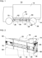
- the Figure 1 shows a motor vehicle 10.
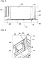
- the Figures 2 to 4 show sections of a longitudinal outer side of the motor vehicle 10 in different views.
- the motor vehicle 10 is preferably designed as a truck, as shown.
- the truck is preferably designed as a so-called chassis vehicle or has a body 12, e.g. a loading body.
- the truck can have, for example, a fifth wheel coupling for coupling a semi-trailer (not shown in Figure 1)
- the motor vehicle 10 is designed, for example, as a bus, a construction machine or an agricultural machine. It is also possible that the motor vehicle 10 is not designed as a commercial vehicle, but rather as a passenger car, for example.
- the motor vehicle 10 can have a vehicle frame 14.
- the body 12 or semi-trailer can be supported on the vehicle frame 14.
- the vehicle frame 14 can preferably be designed as a ladder frame.
- the ladder frame can, for example, have two essentially parallel main longitudinal members.
- the two main longitudinal members can be connected to one another by a plurality of cross members.
- the plurality of cross members can be spaced apart from one another along a longitudinal axis of the motor vehicle 10.
- the vehicle frame 14 can be designed as a lattice frame, for example, in an embodiment of the motor vehicle 10 as a truck or a bus.
- the motor vehicle 10 is preferably electrically driven.
- the motor vehicle 10 can be driven by means of a central electric drive.
- the central electric drive can be arranged, for example, underneath a driver's cab and/or between the two main longitudinal members of the vehicle frame 14.
- the motor vehicle 10 can be driven, for example, by means of several electric wheel hub drives or several electric drives close to the wheels.
- the motor vehicle 10 has at least one energy storage device 16 and a crash structure 18.
- the motor vehicle 10 also has a first trim part 20 and a second trim part 22.
- the energy storage device 16 can be designed, for example, as a fuel tank (e.g. pressure tank) for storing fuel, e.g. diesel, gasoline, hydrogen, fuel gas, etc.
- the fuel tank can be connected to a drive unit of the motor vehicle 10 for supplying the fuel.
- the energy storage device 16 is preferably designed as a traction battery for storing electrical energy.
- the traction battery can be charged externally, for example, via an electrical charging cable connected to a charging socket of the motor vehicle 10.
- the traction battery can supply at least one electric drive of the motor vehicle 10 with electrical energy.
- the energy storage device 16 can be arranged concealed behind the crash structure 18. An outer side or a side of the energy storage device 16 facing away from the vehicle frame 14 (e.g. longitudinal) can be protected by the crash structure 18, e.g. in the event of a side impact on the crash structure 18.
- the energy storage device 16 can be arranged between the vehicle frame 14 and the crash structure 18 (e.g. with respect to a transverse axis of the motor vehicle 10).
- the energy storage device 16 can be arranged between a front axle and a rear axle of the motor vehicle 10.
- the energy storage device 16 can be attached to the vehicle frame 14, preferably to an outer longitudinal side of one of the main longitudinal members of the vehicle frame 14.
- the crash structure 18 can be carried or attached to the energy storage device 16, preferably to a (e.g. longitudinal) side surface of the energy storage device 16, which is directed away from the vehicle frame 14 or outwards.
- the crash structure 18 can be attached to a housing of the energy storage device 16, e.g. by means of a screw connection.
- the crash structure 18 is designed to deform in a predetermined manner while dissipating energy in the event of an impact in order to dissipate crash energy.
- the crash structure 18 can preferably be designed to plastically deform in a predetermined manner while dissipating energy in the event of a side impact on the crash structure 18 and/or the trim parts 20, 22.
- the crash structure 18 can be arranged between a front axle and a rear axle of the motor vehicle 10.
- the crash structure 18 can cover a section of a longitudinal side (e.g. driver's longitudinal side or passenger's longitudinal side) of the motor vehicle 10 to protect it from impact energy.
- the crash structure 18 can be arranged behind a fender for the front axle and/or in front of a fender for the rear axle with respect to a forward travel direction of the motor vehicle 10.
- the crash structure 18 covers an outer side or outer longitudinal side of the energy storage device 16 in a protective manner.
- the crash structure 18 can essentially completely cover or protect an outer longitudinal side of the energy storage device 16.
- the crash structure 18 can extend essentially over an entire height and/or length (with respect to a longitudinal axis of the motor vehicle 10) of the energy storage device 16.
- the crash structure 18 can extend essentially parallel to a longitudinal axis of the motor vehicle 10.
- the crash structure 18 is preferably arranged at the level of a front axle, a rear axle and/or the vehicle frame 14 of the motor vehicle 10.
- the crash structure 18 is advantageously aligned vertically.
- the crash structure 18 is particularly preferably located in a vertical alignment plane which, for example, runs parallel to a longitudinal axis of the motor vehicle 10 or perpendicular to a transverse axis of the motor vehicle 10.
- the crash structure 18 is preferably essentially plate-shaped and/or rectangular.
- the crash structure 18 can be designed as a crash panel.
- the crash structure 18 can preferably be designed as a rolled profile, an extruded profile or a pressed part.
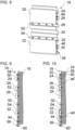
- the crash structure 18 is profiled, as shown in detail below using the Figure 5 is explained in more detail.
- the crash structure 18 can preferably have several profiled sheets 24, 26, 28, 30, 32, 34.
- the profiled sheets 24, 26, 28, 30, 32, 34 can preferably be arranged one above the other. For example, it is also possible to arrange them next to each other.
- the profiled sheets 24, 26, 28, 30, 32, 34 are preferably aligned horizontally.
- the profiled sheets 24, 26, 28, 30, 32, 34 can deform in a predetermined manner during an impact while dissipating energy, in order to protect the energy storage device 16, for example.
- the profiled tracks 24, 26, 28, 30, 32, 34 are preferably parallel to one another.
- the profiled tracks 24, 26, 28, 30, 32, 34 can, for example, run parallel to a longitudinal axis of the motor vehicle 10 or the crash structure 18. It is possible for the crash structure 18 to have more or fewer than the six profiled tracks 24, 26, 28, 30, 32, 34, e.g. two, three, four, five, seven, eight, etc. profiled tracks.
- the profiled sheets 24, 26, 28, 30, 32, 34 can, for example, have a U-shaped, V-shaped or wave-shaped cross-section in a plane that is transverse to a longitudinal extension direction of the plurality of profiled sheets 24, 26, 28, 30, 32, 34.
- the profiled strips 24, 26, 28, 30, 32, 34 can be at least partially of different widths, wherein a width of the profiled strips 24, 26, 28, 30, 32, 34 is measured with respect to a transverse axis of the crash structure 18 or the motor vehicle 10.
- the transverse axis can run perpendicular to the preferably vertical alignment plane of the crash structure 18.
- the top profile sheet 24 may be less wide than the top profile sheet 26.
- the top profile sheet 26 may be less wide than the middle profile sheet 28.
- the middle profile sheet 28 may be the widest profile sheet of the profile sheets 24, 26, 28, 30, 32, 34.
- the bottom profile sheet 32 may be wider than the bottom profile sheet 34.
- the crash structure 18 can be reinforced and/or widened in a central section of the crash structure 18 compared to an upper section of the crash structure 18 and/or a lower section of the crash structure 18.
- the upper section can have the upper profiled sheet 24 and/or 26.
- the middle section can have the middle profiled sheet 28 and/or 30.
- the lower section can have the lower profiled sheet 32 and/or 34.
- the central section can be arranged between the upper section and the lower section.
- An effective width and/or profiling of the crash structure 18 can be greatest in a central section.
- the effective width can refer to the respective maximum width of the profiled sheet(s) in the respective section of the crash structure 18.
- the roof surfaces of the profiled sheets 24, 26, 28, 30, 32, 34 can face away from the energy storage device 16.
- the roof surface of the upper profiled sheet 24 and/or 26 can slope downwards, so that the width of the upper profiled sheet 24 and/or 26 decreases upwards in a vertical direction.
- the roof surface of the middle profiled sheet 28 and/or 30 can have a substantially constant width and can preferably be aligned vertically.
- the roof surface of the lower profiled sheet 32 and/or 34 can slope downwards, so that the width of the lower profiled sheet 32 and/or 34 decreases downwards in a vertical direction.
- Such a design can enable the cladding parts 20, 22 to be mounted on the crash structure 18 in a space-saving manner. It is also possible for the crash structure 18 to be adapted upwards and downwards in this way to the potentially lower crash loads there.
- one of the profile tracks 24, 26, 28, 30, 32, 34 is at the level of at least one environmental detection sensor 36 (see Figures 1 and 2 ) of the motor vehicle 10.
- at least one environmental detection sensor 36 see Figures 1 and 2
- the profile sheet 30 is arranged substantially at the same height as the at least one environment detection sensor 36.
- the environment detection sensor 36 can be attached to a fender of the motor vehicle 10, preferably to the fender of a front axle or rear axle of the motor vehicle 10.
- the environment detection sensor 36 can detect an environment, preferably a blind spot, of the motor vehicle 10.
- the environment detection sensor 36 can output signals that are evaluated by a turning assistance system and/or a blind spot monitoring system of the motor vehicle 10.
- the environment detection sensor 36 can be directed in and/or against a forward direction of travel of the motor vehicle 10.
- the environment detection sensor 36 can preferably have at least one radar sensor.
- the profiled track 30 at the level of the environment detection sensor 36 can be designed in such a way that a field of vision (e.g. a cone of vision) with respect to the environment detection sensor 36 is cleared or not impaired by the profiled track 30.
- the field of vision can run along the crash structure 18, in particular along the profiled track 30.
- a roof surface of the profiled track 30 can be set back relative to the profiled track 28 arranged above it and relative to the profiled track 32 arranged below it.
- a roof surface of the profiled track 30 can be set back relative to the environment detection sensor 36, e.g. with respect to a transverse axis of the motor vehicle 10.
- the energy storage device 16 it is possible for the energy storage device 16 to have a plurality of battery modules arranged one above the other.
- the energy storage device 16 has four battery modules arranged one above the other.
- the crash structure 18 can be connected to the energy storage device 16 in such a way that it holds the plurality of battery modules of the energy storage device 16 together.
- the crash structure 18 can be attached or fastened to the plurality of battery modules of the energy storage device 16, e.g. to the respective housings of the battery modules.
- the crash structure 18 can be attached directly to the battery modules, e.g. screwed.
- at least one fastening strip can be arranged between the crash structure 18 and the battery modules of the energy storage device 16 (not shown).
- the fastening strip is preferably aligned vertically.
- the fastening strip can be attached or attached to the multiple battery modules of the energy storage device 16, e.g. to respective housings of the battery modules.
- the fastening strip can preferably be screwed to the battery modules.
- the fastening strip can hold the multiple battery modules together.
- the crash structure 18 can be attached to the battery modules via the fastening strip, preferably by means of screw connection(s).
- At least one section 38 of the crash structure 18 protrudes over the energy storage device 16 along a longitudinal axis of the crash structure 18 or along a longitudinal extension direction of the profiled sheets 24, 26, 28, 30, 32, 34.
- the Figures 2 to 4 show, by way of example, the protruding section 38 which protrudes beyond the energy storage device 16 in the opposite direction of travel of the motor vehicle 10, i.e., for example, near the rear axle of the motor vehicle 10.
- a protruding section which protrudes beyond the energy storage device 16 in the forward direction of travel of the motor vehicle 10, i.e., for example, near the front axle of the motor vehicle 10, is included.
- a support structure 40 can be arranged between the protruding section 38 and the energy storage device 16.
- the protruding section 38 can be attached to the support structure 40, preferably by means of screw connection(s).
- the support structure 40 can support a rear side or a side of the protruding section 38 facing the vehicle frame 14 on the energy storage device 16.
- the support structure 40 supports the protruding section 38 on an outside of the energy storage device 16 facing opposite to the forward direction of travel of the motor vehicle 10, particularly preferably by means of several ribs 42.
- the ribs 42 can be arranged one above the other.
- the ribs 42 can be parallel to one another.
- the ribs 42 can be designed in the form of triangular plates, for example.
- the ribs 42 can additionally stiffen the support structure 40.
- the support structure 40 can be designed as a welded construction or a cast construction.
- the support structure 40 can preferably, together with the protruding section 38 of the crash structure 18, cover at least one (e.g. electrical) device 44 in a protective manner.
- the at least one device 44 can be arranged on an outside of the energy storage device 16 facing opposite to the forward direction of travel of the motor vehicle 10.
- the at least one device 44 can, for example, be carried and/or attached to the energy storage device 16, e.g. on a housing of the energy storage device 16.
- the at least one device 44 can be carried and/or attached to the outside of the energy storage device 16 facing opposite to the forward direction of travel, e.g. by means of screw connection(s).
- a support structure can be arranged between a section of the crash structure 18 that projects over the energy storage device 16 in the forward direction of travel and the energy storage device 16 (not shown).
- This support structure can in principle be designed like the support structure 40 explained.
- This support structure can, for example, protectively cover a device (e.g. electrical) on an outside of the energy storage device 16 facing in the forward direction of travel.
- the at least one device 44 can preferably be at least one high-voltage component, which is preferably operated with alternating voltages above 30 V up to, for example, 1 kV or with direct voltages above 60 V up to, for example, 1.5 kV.
- the at least one device 44 can have a (e.g. high-voltage) control unit, preferably a charging control unit for controlling a charging process of the energy storage device 16.
- the at least one electrical device 44 can alternatively or additionally have an electrical (e.g. high-voltage) safety device.
- the electrical safety device can, for example, have at least one charging contactor, at least one fuse, a voltmeter and/or an ammeter.
- the at least one device 44 can alternatively or additionally have a charging socket for connecting an electrical charging cable for charging the energy storage device 16.
- the trim parts 20, 22 can be arranged between a front axle and a rear axle of the motor vehicle 10.
- the trim parts 20, 22 can be arranged behind a fender for the front axle and/or in front of a fender for the rear axle with respect to a forward travel direction of the motor vehicle 10.
- the cladding parts 20, 22 each cover a section of an outer side (e.g. outer longitudinal side, such as driver's longitudinal side or passenger's longitudinal side) of the crash structure 18.
- the outer side faces away from the energy storage device 16 or faces outwards.
- the first or upper covering part 20 covers or covers an upper, strip-shaped section of the outside of the crash structure 18.
- the upper section can, for example, have the profile strip 24 and/or 26.
- the upper section can, for example, have a height between 1/5 and 1/2 of a total height of the crash structure 18, preferably around 1/3 of the total height.
- the second or lower cladding part 22 covers or covers a lower, strip-shaped section of the crash structure 18.
- the lower section can, for example, have the profile strip 32 and/or 34.
- the lower section can, for example, have a height between 1/5 and 1/2 of a total height of the crash structure 18, preferably around 1/3 of the total height.
- the cladding parts 20, 22 can be arranged parallel, one above the other and preferably spaced apart from one another.
- a middle section of the outside of the crash structure can be arranged between the cladding parts 20 and 22 with respect to a vertical axis.
- the middle section can not be covered by the cladding parts 20 and 22.
- the middle section can have the profile strip 28 and/or 30, for example.
- the middle section can have a height of between 100 mm and 300 mm, or a distance between the cladding parts 20 and 22 can be between 100 mm and 300 mm, for example.
- the cladding parts 20, 22 can each extend along an entire length of the outside or the crash structure 18, e.g. parallel to the profiled strips 24 - 34 or parallel to a longitudinal axis of the crash structure 18 or of the motor vehicle 10.
- the trim parts 20, 22 can extend substantially parallel to a longitudinal axis of the motor vehicle 10.
- the trim parts 20, 22 are at the level of a front axle, a rear axle and/or the vehicle frame 14 of the motor vehicle 10
- the trim parts 20, 22 are advantageously aligned in a vertical plane or lie in a vertical plane.
- the trim parts 20, 22 are particularly preferably located in a common vertical alignment plane which, for example, runs parallel to a longitudinal axis of the motor vehicle 10 or runs perpendicular to a transverse axis of the motor vehicle 10.
- the cladding parts 20, 22 are strip-shaped, preferably with a substantially horizontally oriented longitudinal direction. In addition, the cladding parts 20, 22 can preferably be rectangular. The cladding parts 20, 22 can be designed as planks. The cladding parts 20, 22 can be designed as identical parts and used, for example, on a cover, as shown. The cladding parts 20, 22 are preferably designed as extruded profiles, e.g. aluminum extruded profiles.
- the cladding parts 20, 22 each have a planar (or smooth or even) outer side.
- the outer side faces away from the profiled crash structure 18 or the outer side of the crash structure 18.
- the inner sides or rear sides of the trim parts 20, 22 can be adapted to the profiled crash structure 18.
- the inner sides face the profiled crash structure 18 or the outer side of the crash structure 18.
- the inner sides of the cladding parts 20, 22 can be profiled.
- the profiled inner sides can interlock with the profiled crash structure 18.
- the inside of the first trim part 20 can have a profiled track 46 and/or the inside of the second trim part 22 can have a profiled track 48.
- the profiled tracks 46 and 48 can run parallel to one another.
- the profiled track 46 and/or 48 can run parallel to the profiled tracks 24 - 34.
- the profiled track 46 can be arranged between the profiled tracks 24 and 28.
- the profiled track 48 can be arranged between the profiled tracks 32 and 34.
- the profiled track 46 and/or 48 has at least one recess (e.g. a groove, a longitudinal channel along the profiled track and/or a depression) for a portion of a fastening element, e.g. a screw head of a screw, wherein the fastening element fastens the crash structure 18 to the energy storage device 16 (e.g. a housing thereof) (see e.g. Figure 10 ).
- a fastening element e.g. a screw head of a screw
- the trim parts 20, 22 can be attached or held on the crash structure 18 with at least one bracket 50, 52, 54, 56.
- the first trim part 20 can be held by the brackets 50, 52.
- the second trim part 22 can be held by the brackets 54, 56.
- the brackets 50 and 56 can be designed as identical parts.
- the brackets 52 and 54 can be designed as identical parts.
- the holders 50, 56 can each be cranked to hold the first and second trim parts 20, 22.
- the holder 50 can preferably be cranked in opposite directions, preferably downwards and upwards, particularly preferably multiple times and alternately.
- the first trim part 20 can be inserted into the holder 50 laterally or parallel to the longitudinal axis of the trim parts 20, 22 / the crash structure 18, preferably in such a way that there is essentially only one degree of freedom of movement in the insertion direction. This can be achieved, for example, by the cranks of the holder 50.
- the second trim part 22 can be inserted into the holder 56 laterally or parallel to the longitudinal axis of the trim parts 20, 22 / the crash structure 18.
- the brackets 50, 56 can each be attached to the crash structure 18, preferably by means of screw connection(s). Particularly preferably, the fastening elements 58, 60 that attach the brackets 50, 56 to the crash structure 18 at least partially simultaneously attach the crash structure 18 to the energy storage device 16 or its housing. It is preferred that the brackets 50, 56 are already firmly attached to the crash structure 18 when the covering part 20 or 22 is inserted. After insertion, the brackets 50, 56 can be covered or concealed by the covering parts 20, 22.
- the inside of the first trim part 20 can encompass the cranked bracket 50 and also be supported on the cranked bracket 50, preferably a vertical surface of the cranked bracket 50.
- the inside of the second trim part 22 can encompass the cranked bracket 56 and also be supported on the cranked bracket 56.
- the Figure 10 It is also particularly preferred that the inner sides of the trim parts 20 and 22 can be supported directly on sections of the fastening elements 58 and 60 in the event of a crash when the trim parts 20 and 22 are pressed inwards.
- the inner side of the first trim part 20 can be supported on the end faces of the screw heads of the fastening elements 58 designed as screws in the event of a crash.
- the inside of the second trim part 22 can in turn be supported on the end faces of the screw heads of the fastening elements 60 designed as screws in the event of a crash.
- the brackets 52, 54 can have a plurality of holding elements.
- the holding elements can each be arranged in a row, e.g. parallel to the longitudinal axis of the trim parts 20, 22 or the crash structure 18.
- the first trim part 20 can be inserted into the holding elements of the bracket 52 laterally or parallel to the longitudinal axis of the trim parts 20, 22 / the crash structure 18, preferably in such a way that there is essentially only one degree of freedom of movement in the insertion direction. This can be achieved, for example, by a dovetail configuration or connection between the bracket 50 and the first trim part 20.
- the second trim part 22 can be inserted into the holding elements of the bracket 54 laterally or parallel to the longitudinal axis of the trim parts 20, 22 / the crash structure 18.
- the use of a dovetail connection can enable a particularly flat connection between the cladding parts 20, 22 and the crash structure 18.
- the holding elements of the brackets 52, 54 can each be attached to the crash structure 18, preferably by means of screw connection(s). Particularly preferably, the fastening elements that attach the brackets 52, 54 to the crash structure 18 at least partially simultaneously attach the crash structure 18 to the energy storage device 16 or its housing. It is also preferred that the brackets 52, 54 are not yet tightened or firmly attached to the crash structure 18 when the trim part 20 or 22 is inserted and are only tightened after insertion.
- the inside of the first trim part 20 can grip around the holder 52 and rest on it.
- the inside of the second trim part 22 can grip around the holder 54 and also rest on it.
- trim parts 20, 22 may be suspended in corresponding holders on the crash structure 18.
- the brackets 50 - 56 can be arranged in valleys between the profiled sheets 24 - 32. In particular, the bracket 50 can be arranged above the profiled sheet 24.
- the Bracket 52 can be arranged between the profiled tracks 26 and 28.
- Bracket 54 can be arranged between the profiled tracks 30 and 32.
- Bracket 56 can be arranged below the profiled track 34.
- trim parts 62, 64, 66 and/or 68 can be included.
- the further trim parts 62, 64, 66, 68 can be arranged offset from the crash structure 18 with respect to a longitudinal axis of the motor vehicle 10 or the crash structure 18.
- the further trim parts 62, 64, 66, 68 can be arranged as an extension of the trim parts 20 and 22, respectively.
- the third trim part 62 can extend the first trim part 20 in a forward direction of travel of the motor vehicle 10.
- the fourth trim part 64 can extend the second trim part 22 in a forward direction of travel of the motor vehicle 10.
- the fifth trim part 66 can extend the first trim part 20 against a forward direction of travel of the motor vehicle 10.
- the sixth trim part 68 can extend the second trim part 22 against a forward direction of travel of the motor vehicle 10.
- the further trim parts 62, 64 can be arranged between a front axle of the motor vehicle 10 and the trim parts 20, 22.
- the further trim parts 66, 68 can be arranged between a rear axle of the motor vehicle 10 and the trim parts 20, 22.
- the additional panel parts 62 - 68 can be attached to the vehicle frame 14, for example, via supports.
- the additional panel parts 62 - 68 can cover additional components, e.g. a compressed air system 70 of the motor vehicle 10, as shown by way of example for the additional panel parts 62 and 64.
- the further cladding parts 62, 64, 66, 68 can be strip-shaped and have a planar outer side that faces outwards or away from the vehicle frame 14.
- the further cladding parts 62, 64, 66, 68 can therefore preferably be designed as underrun protection of the motor vehicle 10.
Landscapes
- Engineering & Computer Science (AREA)
- Mechanical Engineering (AREA)
- Chemical & Material Sciences (AREA)
- Combustion & Propulsion (AREA)
- Transportation (AREA)
- Life Sciences & Earth Sciences (AREA)
- Sustainable Development (AREA)
- Sustainable Energy (AREA)
- Body Structure For Vehicles (AREA)
- Vibration Dampers (AREA)
Claims (15)
- Dispositif pour un véhicule automobile (10), de préférence un véhicule utilitaire, comprenant :un accumulateur d'énergie (16), de préférence une batterie de traction ou un réservoir de carburant ;une structure de collision (18), qui est profilée, qui recouvre de manière protectrice une face extérieure de l'accumulateur d'énergie (16) et qui est conçue pour se déformer de manière prédéterminée en cas de choc avec dissipation d'énergie,le dispositif étant caractérisé en ce qu'il comprend en outre :une première pièce d'habillage (20) qui est en forme de bande, qui habille une partie supérieure en forme de bande d'une face extérieure de la structure de collision (18) opposée à l'accumulateur d'énergie (16) et qui présente une face extérieure plane opposée à la structure de collision (18) ; etune deuxième pièce d'habillage (22) qui est en forme de bande, qui habille une partie inférieure en forme de bande de la face extérieure de la structure de collision (18) et qui présente une face extérieure plane qui est opposée à la structure de collision (18).
- Dispositif selon la revendication 1, dans lequel :la première pièce d'habillage (20) et/ou la deuxième pièce d'habillage (22) présente une face intérieure tournée vers la face extérieure de la structure de collision (18), qui est adaptée à la structure de collision (18) ; et/oula face extérieure plane de la première pièce d'habillage (20) et/ou la face extérieure plane de la deuxième pièce d'habillage (22) est sensiblement dans un plan vertical avec une surface de toit d'une bande profilée (28) en saillie de la structure de collision (18), ou en retrait de cette surface de toit.
- Dispositif selon la revendication 1 ou la revendication 2, dans lequel :la face intérieure de la première pièce d'habillage (20) et/ou de la deuxième pièce d'habillage (22) est profilée, de préférence adaptée à la structure de collision (18) et/ou de manière alternée avec celle-ci ; et/oula face intérieure de la première pièce d'habillage (20) et/ou de la deuxième pièce d'habillage (22) et la structure de collision (18) s'interpénètrent, une bande profilée (46, 48) de la face intérieure étant de préférence disposée entre deux bandes profilées (24, 26 ; 32, 34) de la structure de collision (18).
- Dispositif selon l'une des revendications précédentes, dans lequel :
la première pièce d'habillage (20) et la deuxième pièce d'habillage (22) sont parallèles, alignées verticalement, espacées et/ou s'étendent sensiblement sur toute une longueur de la face externe de la structure de collision (18). - Dispositif selon l'une des revendications précédentes, comprenant en outre :
au moins un support (50, 52, 54, 56) maintenant la première pièce d'habillage (20) et/ou la deuxième pièce d'habillage (22) sur la structure de collision (18). - Dispositif selon la revendication 5, dans lequel :la première pièce d'habillage (20) et/ou la deuxième pièce d'habillage (22) est insérée dans ledit au moins un support (50, 52, 54, 56), de préférence au moyen d'une liaison en queue d'aronde et/ou d'une liaison par des décrochements, de sorte qu'une combinaison à structure plate de la première et/ou de la deuxième pièce d'habillage (20, 22) et de la structure de collision (18) est de préférence réalisée ; et/oula première pièce d'habillage (20) et/ou la deuxième pièce d'habillage (22) est accrochée audit au moins un support (50, 52, 54, 56).
- Dispositif selon la revendication 5 ou la revendication 6, dans lequel :
la première pièce d'habillage (20) et/ou la deuxième pièce d'habillage (22) recouvre ledit au moins un support (50, 56). - Dispositif selon l'une des revendications 5 à 7, dans lequel :ledit au moins un support (50, 56) présente au moins un décrochement, de préférence au moins deux décrochements dans des directions opposées,de préférence, un décrochement de chaque support (50, 56) s'emboîtant avec la première ou la deuxième pièce d'habillage (20, 22), et un autre décrochement de chaque support (50, 56) supportant à plat la première ou la deuxième pièce d'habillage (20, 22).
- Dispositif selon l'une des revendications 5 à 8, dans lequel :
ledit au moins un support (50, 52, 54, 56) est disposé dans au moins une portion de vallée adjacente à une bande profilée (24, 34) de la structure de collision (18) ou entre deux bandes profilées (26, 28 ; 30, 32) de la structure de collision (18). - Dispositif selon l'une des revendications précédentes, comprenant en outre :plusieurs éléments de fixation (58, 60), de préférence une rangée de vis, qui fixent la structure de collision (18) à l'accumulateur d'énergie (16) et/ou qui fixent la première pièce d'habillage (20) et/ou la deuxième pièce d'habillage (22) à la structure de collision (18),la première pièce d'habillage (20) et/ou la deuxième pièce d'habillage (22) recouvrant la pluralité d'éléments de fixation (58, 60).
- Dispositif selon l'une des revendications précédentes, comprenant en outre :
au moins une autre pièce d'habillage (62, 64, 66, 68), décalée par rapport à la structure de collision (18) pour constituer un prolongement de la première pièce d'habillage (20) et/ou de la deuxième pièce d'habillage (22), ayant la forme d'une bande et présentant une face extérieure plane. - Dispositif selon la revendication 11, dans lequel :ladite au moins une autre pièce d'habillage (62, 64, 66, 68) est agencée en tant que protection anti-encastrement ; et/ouladite au moins une autre pièce d'habillage (62, 64, 66, 68) est agencée de manière décalée à côté de la face extérieure de la structure de collision (18) selon une vue de la face extérieure de la structure de collision (18) .
- Dispositif selon la revendication 11 ou la revendication 12, dans lequel ladite au moins une autre pièce d'habillage (62, 64, 66, 68) comprend :une troisième pièce d'habillage (62) agencée en tant que prolongement de la première pièce d'habillage (20) ; etune quatrième pièce d'habillage (64) agencée en tant que prolongement de la deuxième pièce d'habillage (22), ladite au moins une autre pièce d'habillage (62, 64, 66, 68) comprenant de préférence en outre :une cinquième pièce d'habillage (66) agencée sur un côté de la première pièce d'habillage (20) opposé à la troisième pièce d'habillage (62) en tant que prolongement de la première pièce d'habillage (20), et/ouune sixième pièce d'habillage (68) disposée sur un côté de la deuxième pièce d'habillage (22) opposé à la quatrième pièce d'habillage (64), en tant que prolongement de la deuxième pièce d'habillage (22).
- Dispositif selon l'une des revendications précédentes, dans lequel :la première pièce d'habillage (20) et la deuxième pièce d'habillage (22) sont réalisées sous forme de pièces identiques ; et/oula structure de collision (18) comporte plusieurs bandes profilées (24, 26, 28, 30, 32, 34), qui, de préférence :- sont disposées les unes au-dessus des autres ; et/ou- s'étendent sensiblement parallèlement les unes aux autres ; et/ou- présentent chacune une section transversale en forme de U, de V ou d'onde, de préférence dans un plan transversal à une direction d'extension longitudinale de la pluralité de bandes profilées (24, 26, 28, 30, 32, 34) .
- Véhicule automobile (10), de préférence véhicule utilitaire, comprenant :un essieu avant ;un essieu arrière ;un châssis de véhicule (14), de préférence un châssis en échelle ; etun dispositif selon l'une des revendications précédentes, ledit dispositif étant disposé entre l'essieu avant et l'essieu arrière et/ou fixé au châssis (14) du véhicule, de préférence au même niveau que l'essieu avant et l'essieu arrière.
Applications Claiming Priority (1)
| Application Number | Priority Date | Filing Date | Title |
|---|---|---|---|
| DE102021127606.3A DE102021127606A1 (de) | 2021-10-25 | 2021-10-25 | Verkleidete Crashstruktur für Energiespeicher |
Publications (2)
| Publication Number | Publication Date |
|---|---|
| EP4169754A1 EP4169754A1 (fr) | 2023-04-26 |
| EP4169754B1 true EP4169754B1 (fr) | 2024-06-19 |
Family
ID=83690523
Family Applications (1)
| Application Number | Title | Priority Date | Filing Date |
|---|---|---|---|
| EP22200863.3A Active EP4169754B1 (fr) | 2021-10-25 | 2022-10-11 | Structure de collision revêtue pour accumulateur d'énergie |
Country Status (3)
| Country | Link |
|---|---|
| EP (1) | EP4169754B1 (fr) |
| KR (1) | KR20230059152A (fr) |
| DE (1) | DE102021127606A1 (fr) |
Families Citing this family (1)
| Publication number | Priority date | Publication date | Assignee | Title |
|---|---|---|---|---|
| WO2025054068A1 (fr) * | 2023-09-06 | 2025-03-13 | Daimler Truck North America Llc | Dispositif de protection d'une batterie de véhicule contre les chocs latéraux |
Family Cites Families (8)
| Publication number | Priority date | Publication date | Assignee | Title |
|---|---|---|---|---|
| DE4234120A1 (de) | 1992-10-09 | 1994-04-14 | Man Nutzfahrzeuge Ag | Nutzfahrzeug, insbesondere Frontlenker-Lastkraftwagen |
| DE10150052B4 (de) | 2001-10-10 | 2005-07-14 | Daimlerchrysler Ag | Fahrgestell für Nutzfahrzeuge |
| DE102012019023A1 (de) | 2012-09-26 | 2014-03-27 | Man Truck & Bus Ag | Rahmentragstruktur mit einem Aufnahmebehältnis für zumindest eine Nutzfahrzeugkomponente |
| CN104802860B (zh) * | 2014-01-27 | 2019-06-07 | 比亚迪股份有限公司 | 电动卡车的车架组件和电动卡车 |
| DE102017102744A1 (de) | 2017-02-13 | 2018-08-16 | Voith Patent Gmbh | Kollisionsschutzsystem für Nutzfahrzeuge |
| DE102018121227A1 (de) | 2018-08-30 | 2020-03-05 | Man Truck & Bus Se | Modular aufgebautes Nutzfahrzeug |
| DE102018122854A1 (de) | 2018-09-18 | 2020-03-19 | Hörmann Automotive GmbH | Chassis für ein Straßenfahrzeug mit elektrischem Energiespeicher |
| EP3921197B1 (fr) * | 2019-02-04 | 2023-06-28 | Volvo Truck Corporation | Véhicule utilitaire à alimentation électrique ayant une structure de batterie |
-
2021
- 2021-10-25 DE DE102021127606.3A patent/DE102021127606A1/de active Pending
-
2022
- 2022-10-11 EP EP22200863.3A patent/EP4169754B1/fr active Active
- 2022-10-21 KR KR1020220136228A patent/KR20230059152A/ko active Pending
Also Published As
| Publication number | Publication date |
|---|---|
| EP4169754A1 (fr) | 2023-04-26 |
| DE102021127606A1 (de) | 2023-04-27 |
| KR20230059152A (ko) | 2023-05-03 |
Similar Documents
| Publication | Publication Date | Title |
|---|---|---|
| EP3617039B1 (fr) | Dispositif de support d'au moins une batterie pour un véhicule automobile | |
| EP2729348B1 (fr) | Structure de plancher pour un véhicule | |
| EP3588609B1 (fr) | Boîtier de de batterie ainsi que véhicule automobile doté d'un tel boîtier de batterie | |
| DE102017126949B4 (de) | Batterieeinrichtung für ein wenigstens teilweise elektrisch betriebenes Kraftfahrzeug | |
| DE102019123844A1 (de) | Fahrzeugboden für eine Energiespeicher-Bodengruppe eines Kraftwagens | |
| DE102016217935A1 (de) | Traktionsbatterie mit eingeschobenen Batteriemodulen und Kraftfahrzeug mit elektrischem Fahrantrieb | |
| DE102009006990A1 (de) | Karosserieaufbau mit einem Hohlraum | |
| EP3710342A1 (fr) | Ensemble formant marchepied d'une carrosserie d'un véhicule à moteur à fonctionnement électrique | |
| DE102019123845A1 (de) | Energiespeicher-Bodengruppe für einen Kraftwagen | |
| DE102011050707B4 (de) | Lagerung eines elektrischen oder elektronischen Bauteils in einem Motorraum eines Kraftfahrzeugs | |
| DE102019211266B4 (de) | Batteriegehäuse und Kraftfahrzeug | |
| DE102018210126A1 (de) | Strukturbauteil, Batteriegehäuse und Kraftfahrzeug mit einem solchen Batteriegehäuse | |
| DE102018216833A1 (de) | Batteriegehäuseunterteil zur Aufnahme zumindest eines Batteriemoduls, Kraftfahrzeug und Verfahren zum Herstellen eines Batteriegehäuseunterteils | |
| DE102019123846A1 (de) | Energiespeicher-Bodengruppe für einen Kraftwagen | |
| EP3616956B1 (fr) | Module énergétique pour un véhicule utilitaire | |
| DE102020005603A1 (de) | Traktionsbatterie für ein Fahrzeug und Verfahren zur Herstellung eines Fahrzeugs | |
| DE4234120A1 (de) | Nutzfahrzeug, insbesondere Frontlenker-Lastkraftwagen | |
| DE102021127621A1 (de) | Crashstruktur für Energiespeicher | |
| EP4169754A1 (fr) | Structure de collision revêtue pour accumulateur d'énergie | |
| DE102023103649A1 (de) | Fahrzeug | |
| EP4173864B1 (fr) | Structure de revêtement latéral et de collision pour accumulateur d'énergie d'un véhicule automobile | |
| DE102012013790B4 (de) | Anordnung eines Kraftstofftanks sowie Kraftfahrzeug mit einer solchen Anordnung | |
| EP4169773A1 (fr) | Dispositif d'inclinaison d'un véhicule automobile | |
| EP4163193B1 (fr) | Structure avant pour un véhicule automobile avec une structure de collision disposée derrière un module de refroidissement | |
| EP4349681A2 (fr) | Locomotive avec cabine centrale et plusieurs superstructures électriques de toit placées sur la cabine |
Legal Events
| Date | Code | Title | Description |
|---|---|---|---|
| PUAI | Public reference made under article 153(3) epc to a published international application that has entered the european phase |
Free format text: ORIGINAL CODE: 0009012 |
|
| STAA | Information on the status of an ep patent application or granted ep patent |
Free format text: STATUS: THE APPLICATION HAS BEEN PUBLISHED |
|
| AK | Designated contracting states |
Kind code of ref document: A1 Designated state(s): AL AT BE BG CH CY CZ DE DK EE ES FI FR GB GR HR HU IE IS IT LI LT LU LV MC ME MK MT NL NO PL PT RO RS SE SI SK SM TR |
|
| STAA | Information on the status of an ep patent application or granted ep patent |
Free format text: STATUS: REQUEST FOR EXAMINATION WAS MADE |
|
| 17P | Request for examination filed |
Effective date: 20230925 |
|
| RBV | Designated contracting states (corrected) |
Designated state(s): AL AT BE BG CH CY CZ DE DK EE ES FI FR GB GR HR HU IE IS IT LI LT LU LV MC ME MK MT NL NO PL PT RO RS SE SI SK SM TR |
|
| GRAP | Despatch of communication of intention to grant a patent |
Free format text: ORIGINAL CODE: EPIDOSNIGR1 |
|
| STAA | Information on the status of an ep patent application or granted ep patent |
Free format text: STATUS: GRANT OF PATENT IS INTENDED |
|
| RIC1 | Information provided on ipc code assigned before grant |
Ipc: B62D 35/00 20060101ALN20240109BHEP Ipc: B60R 19/56 20060101ALN20240109BHEP Ipc: B62D 21/15 20060101ALI20240109BHEP Ipc: B60K 15/03 20060101ALI20240109BHEP Ipc: B60K 1/04 20190101AFI20240109BHEP |
|
| INTG | Intention to grant announced |
Effective date: 20240125 |
|
| GRAS | Grant fee paid |
Free format text: ORIGINAL CODE: EPIDOSNIGR3 |
|
| GRAA | (expected) grant |
Free format text: ORIGINAL CODE: 0009210 |
|
| STAA | Information on the status of an ep patent application or granted ep patent |
Free format text: STATUS: THE PATENT HAS BEEN GRANTED |
|
| AK | Designated contracting states |
Kind code of ref document: B1 Designated state(s): AL AT BE BG CH CY CZ DE DK EE ES FI FR GB GR HR HU IE IS IT LI LT LU LV MC ME MK MT NL NO PL PT RO RS SE SI SK SM TR |
|
| REG | Reference to a national code |
Ref country code: GB Ref legal event code: FG4D Free format text: NOT ENGLISH |
|
| REG | Reference to a national code |
Ref country code: CH Ref legal event code: EP |
|
| REG | Reference to a national code |
Ref country code: DE Ref legal event code: R096 Ref document number: 502022001075 Country of ref document: DE |
|
| REG | Reference to a national code |
Ref country code: NL Ref legal event code: FP |
|
| REG | Reference to a national code |
Ref country code: SE Ref legal event code: TRGR |
|
| PG25 | Lapsed in a contracting state [announced via postgrant information from national office to epo] |
Ref country code: BG Free format text: LAPSE BECAUSE OF FAILURE TO SUBMIT A TRANSLATION OF THE DESCRIPTION OR TO PAY THE FEE WITHIN THE PRESCRIBED TIME-LIMIT Effective date: 20240619 |
|
| PG25 | Lapsed in a contracting state [announced via postgrant information from national office to epo] |
Ref country code: FI Free format text: LAPSE BECAUSE OF FAILURE TO SUBMIT A TRANSLATION OF THE DESCRIPTION OR TO PAY THE FEE WITHIN THE PRESCRIBED TIME-LIMIT Effective date: 20240619 Ref country code: HR Free format text: LAPSE BECAUSE OF FAILURE TO SUBMIT A TRANSLATION OF THE DESCRIPTION OR TO PAY THE FEE WITHIN THE PRESCRIBED TIME-LIMIT Effective date: 20240619 |
|
| REG | Reference to a national code |
Ref country code: LT Ref legal event code: MG9D |
|
| PG25 | Lapsed in a contracting state [announced via postgrant information from national office to epo] |
Ref country code: GR Free format text: LAPSE BECAUSE OF FAILURE TO SUBMIT A TRANSLATION OF THE DESCRIPTION OR TO PAY THE FEE WITHIN THE PRESCRIBED TIME-LIMIT Effective date: 20240920 |
|
| PG25 | Lapsed in a contracting state [announced via postgrant information from national office to epo] |
Ref country code: LV Free format text: LAPSE BECAUSE OF FAILURE TO SUBMIT A TRANSLATION OF THE DESCRIPTION OR TO PAY THE FEE WITHIN THE PRESCRIBED TIME-LIMIT Effective date: 20240619 |
|
| PG25 | Lapsed in a contracting state [announced via postgrant information from national office to epo] |
Ref country code: NO Free format text: LAPSE BECAUSE OF FAILURE TO SUBMIT A TRANSLATION OF THE DESCRIPTION OR TO PAY THE FEE WITHIN THE PRESCRIBED TIME-LIMIT Effective date: 20240919 Ref country code: LV Free format text: LAPSE BECAUSE OF FAILURE TO SUBMIT A TRANSLATION OF THE DESCRIPTION OR TO PAY THE FEE WITHIN THE PRESCRIBED TIME-LIMIT Effective date: 20240619 Ref country code: HR Free format text: LAPSE BECAUSE OF FAILURE TO SUBMIT A TRANSLATION OF THE DESCRIPTION OR TO PAY THE FEE WITHIN THE PRESCRIBED TIME-LIMIT Effective date: 20240619 Ref country code: GR Free format text: LAPSE BECAUSE OF FAILURE TO SUBMIT A TRANSLATION OF THE DESCRIPTION OR TO PAY THE FEE WITHIN THE PRESCRIBED TIME-LIMIT Effective date: 20240920 Ref country code: FI Free format text: LAPSE BECAUSE OF FAILURE TO SUBMIT A TRANSLATION OF THE DESCRIPTION OR TO PAY THE FEE WITHIN THE PRESCRIBED TIME-LIMIT Effective date: 20240619 Ref country code: BG Free format text: LAPSE BECAUSE OF FAILURE TO SUBMIT A TRANSLATION OF THE DESCRIPTION OR TO PAY THE FEE WITHIN THE PRESCRIBED TIME-LIMIT Effective date: 20240619 Ref country code: RS Free format text: LAPSE BECAUSE OF FAILURE TO SUBMIT A TRANSLATION OF THE DESCRIPTION OR TO PAY THE FEE WITHIN THE PRESCRIBED TIME-LIMIT Effective date: 20240919 |
|
| PG25 | Lapsed in a contracting state [announced via postgrant information from national office to epo] |
Ref country code: PT Free format text: LAPSE BECAUSE OF FAILURE TO SUBMIT A TRANSLATION OF THE DESCRIPTION OR TO PAY THE FEE WITHIN THE PRESCRIBED TIME-LIMIT Effective date: 20241021 |
|
| PG25 | Lapsed in a contracting state [announced via postgrant information from national office to epo] |
Ref country code: PT Free format text: LAPSE BECAUSE OF FAILURE TO SUBMIT A TRANSLATION OF THE DESCRIPTION OR TO PAY THE FEE WITHIN THE PRESCRIBED TIME-LIMIT Effective date: 20241021 |
|
| PG25 | Lapsed in a contracting state [announced via postgrant information from national office to epo] |
Ref country code: PL Free format text: LAPSE BECAUSE OF FAILURE TO SUBMIT A TRANSLATION OF THE DESCRIPTION OR TO PAY THE FEE WITHIN THE PRESCRIBED TIME-LIMIT Effective date: 20240619 |
|
| PG25 | Lapsed in a contracting state [announced via postgrant information from national office to epo] |
Ref country code: EE Free format text: LAPSE BECAUSE OF FAILURE TO SUBMIT A TRANSLATION OF THE DESCRIPTION OR TO PAY THE FEE WITHIN THE PRESCRIBED TIME-LIMIT Effective date: 20240619 |
|
| PG25 | Lapsed in a contracting state [announced via postgrant information from national office to epo] |
Ref country code: IS Free format text: LAPSE BECAUSE OF FAILURE TO SUBMIT A TRANSLATION OF THE DESCRIPTION OR TO PAY THE FEE WITHIN THE PRESCRIBED TIME-LIMIT Effective date: 20241019 |
|
| PG25 | Lapsed in a contracting state [announced via postgrant information from national office to epo] |
Ref country code: CZ Free format text: LAPSE BECAUSE OF FAILURE TO SUBMIT A TRANSLATION OF THE DESCRIPTION OR TO PAY THE FEE WITHIN THE PRESCRIBED TIME-LIMIT Effective date: 20240619 |
|
| PG25 | Lapsed in a contracting state [announced via postgrant information from national office to epo] |
Ref country code: RO Free format text: LAPSE BECAUSE OF FAILURE TO SUBMIT A TRANSLATION OF THE DESCRIPTION OR TO PAY THE FEE WITHIN THE PRESCRIBED TIME-LIMIT Effective date: 20240619 Ref country code: SK Free format text: LAPSE BECAUSE OF FAILURE TO SUBMIT A TRANSLATION OF THE DESCRIPTION OR TO PAY THE FEE WITHIN THE PRESCRIBED TIME-LIMIT Effective date: 20240619 |
|
| PG25 | Lapsed in a contracting state [announced via postgrant information from national office to epo] |
Ref country code: SM Free format text: LAPSE BECAUSE OF FAILURE TO SUBMIT A TRANSLATION OF THE DESCRIPTION OR TO PAY THE FEE WITHIN THE PRESCRIBED TIME-LIMIT Effective date: 20240619 Ref country code: ES Free format text: LAPSE BECAUSE OF FAILURE TO SUBMIT A TRANSLATION OF THE DESCRIPTION OR TO PAY THE FEE WITHIN THE PRESCRIBED TIME-LIMIT Effective date: 20240619 |
|
| PG25 | Lapsed in a contracting state [announced via postgrant information from national office to epo] |
Ref country code: SM Free format text: LAPSE BECAUSE OF FAILURE TO SUBMIT A TRANSLATION OF THE DESCRIPTION OR TO PAY THE FEE WITHIN THE PRESCRIBED TIME-LIMIT Effective date: 20240619 Ref country code: SK Free format text: LAPSE BECAUSE OF FAILURE TO SUBMIT A TRANSLATION OF THE DESCRIPTION OR TO PAY THE FEE WITHIN THE PRESCRIBED TIME-LIMIT Effective date: 20240619 Ref country code: RO Free format text: LAPSE BECAUSE OF FAILURE TO SUBMIT A TRANSLATION OF THE DESCRIPTION OR TO PAY THE FEE WITHIN THE PRESCRIBED TIME-LIMIT Effective date: 20240619 Ref country code: PL Free format text: LAPSE BECAUSE OF FAILURE TO SUBMIT A TRANSLATION OF THE DESCRIPTION OR TO PAY THE FEE WITHIN THE PRESCRIBED TIME-LIMIT Effective date: 20240619 Ref country code: IS Free format text: LAPSE BECAUSE OF FAILURE TO SUBMIT A TRANSLATION OF THE DESCRIPTION OR TO PAY THE FEE WITHIN THE PRESCRIBED TIME-LIMIT Effective date: 20241019 Ref country code: ES Free format text: LAPSE BECAUSE OF FAILURE TO SUBMIT A TRANSLATION OF THE DESCRIPTION OR TO PAY THE FEE WITHIN THE PRESCRIBED TIME-LIMIT Effective date: 20240619 Ref country code: EE Free format text: LAPSE BECAUSE OF FAILURE TO SUBMIT A TRANSLATION OF THE DESCRIPTION OR TO PAY THE FEE WITHIN THE PRESCRIBED TIME-LIMIT Effective date: 20240619 Ref country code: CZ Free format text: LAPSE BECAUSE OF FAILURE TO SUBMIT A TRANSLATION OF THE DESCRIPTION OR TO PAY THE FEE WITHIN THE PRESCRIBED TIME-LIMIT Effective date: 20240619 |
|
| REG | Reference to a national code |
Ref country code: DE Ref legal event code: R097 Ref document number: 502022001075 Country of ref document: DE |
|
| PG25 | Lapsed in a contracting state [announced via postgrant information from national office to epo] |
Ref country code: DK Free format text: LAPSE BECAUSE OF FAILURE TO SUBMIT A TRANSLATION OF THE DESCRIPTION OR TO PAY THE FEE WITHIN THE PRESCRIBED TIME-LIMIT Effective date: 20240619 |
|
| PLBE | No opposition filed within time limit |
Free format text: ORIGINAL CODE: 0009261 |
|
| STAA | Information on the status of an ep patent application or granted ep patent |
Free format text: STATUS: NO OPPOSITION FILED WITHIN TIME LIMIT |
|
| 26N | No opposition filed |
Effective date: 20250320 |
|
| PG25 | Lapsed in a contracting state [announced via postgrant information from national office to epo] |
Ref country code: MC Free format text: LAPSE BECAUSE OF FAILURE TO SUBMIT A TRANSLATION OF THE DESCRIPTION OR TO PAY THE FEE WITHIN THE PRESCRIBED TIME-LIMIT Effective date: 20240619 |
|
| PG25 | Lapsed in a contracting state [announced via postgrant information from national office to epo] |
Ref country code: LU Free format text: LAPSE BECAUSE OF NON-PAYMENT OF DUE FEES Effective date: 20241011 Ref country code: BE Free format text: LAPSE BECAUSE OF NON-PAYMENT OF DUE FEES Effective date: 20241031 |
|
| REG | Reference to a national code |
Ref country code: BE Ref legal event code: MM Effective date: 20241031 |
|
| PG25 | Lapsed in a contracting state [announced via postgrant information from national office to epo] |
Ref country code: IE Free format text: LAPSE BECAUSE OF NON-PAYMENT OF DUE FEES Effective date: 20241011 |
|
| PGFP | Annual fee paid to national office [announced via postgrant information from national office to epo] |
Ref country code: NL Payment date: 20251024 Year of fee payment: 4 |
|
| PGFP | Annual fee paid to national office [announced via postgrant information from national office to epo] |
Ref country code: DE Payment date: 20251028 Year of fee payment: 4 |
|
| PGFP | Annual fee paid to national office [announced via postgrant information from national office to epo] |
Ref country code: AT Payment date: 20260113 Year of fee payment: 4 |
|
| PGFP | Annual fee paid to national office [announced via postgrant information from national office to epo] |
Ref country code: IT Payment date: 20251031 Year of fee payment: 4 |
|
| PGFP | Annual fee paid to national office [announced via postgrant information from national office to epo] |
Ref country code: FR Payment date: 20251027 Year of fee payment: 4 |
|
| PGFP | Annual fee paid to national office [announced via postgrant information from national office to epo] |
Ref country code: SE Payment date: 20251024 Year of fee payment: 4 |
|
| PG25 | Lapsed in a contracting state [announced via postgrant information from national office to epo] |
Ref country code: CY Free format text: LAPSE BECAUSE OF FAILURE TO SUBMIT A TRANSLATION OF THE DESCRIPTION OR TO PAY THE FEE WITHIN THE PRESCRIBED TIME-LIMIT; INVALID AB INITIO Effective date: 20221011 |
|
| PG25 | Lapsed in a contracting state [announced via postgrant information from national office to epo] |
Ref country code: HU Free format text: LAPSE BECAUSE OF FAILURE TO SUBMIT A TRANSLATION OF THE DESCRIPTION OR TO PAY THE FEE WITHIN THE PRESCRIBED TIME-LIMIT; INVALID AB INITIO Effective date: 20221011 |