EP4349681A2 - Locomotive avec cabine centrale et plusieurs superstructures électriques de toit placées sur la cabine - Google Patents
Locomotive avec cabine centrale et plusieurs superstructures électriques de toit placées sur la cabine Download PDFInfo
- Publication number
- EP4349681A2 EP4349681A2 EP23198215.8A EP23198215A EP4349681A2 EP 4349681 A2 EP4349681 A2 EP 4349681A2 EP 23198215 A EP23198215 A EP 23198215A EP 4349681 A2 EP4349681 A2 EP 4349681A2
- Authority
- EP
- European Patent Office
- Prior art keywords
- cab
- driver
- locomotive
- antenna
- protective
- Prior art date
- Legal status (The legal status is an assumption and is not a legal conclusion. Google has not performed a legal analysis and makes no representation as to the accuracy of the status listed.)
- Pending
Links
- 230000003137 locomotive effect Effects 0.000 title claims abstract description 73
- 230000000712 assembly Effects 0.000 title 1
- 238000000429 assembly Methods 0.000 title 1
- 230000001681 protective effect Effects 0.000 claims abstract description 80
- 238000011161 development Methods 0.000 description 3
- 230000018109 developmental process Effects 0.000 description 3
- 230000005672 electromagnetic field Effects 0.000 description 3
- 239000002184 metal Substances 0.000 description 3
- 239000006096 absorbing agent Substances 0.000 description 2
- 239000002828 fuel tank Substances 0.000 description 2
- 238000012423 maintenance Methods 0.000 description 2
- 230000035939 shock Effects 0.000 description 2
- UFHFLCQGNIYNRP-UHFFFAOYSA-N Hydrogen Chemical compound [H][H] UFHFLCQGNIYNRP-UHFFFAOYSA-N 0.000 description 1
- 238000004378 air conditioning Methods 0.000 description 1
- 239000000969 carrier Substances 0.000 description 1
- 239000004020 conductor Substances 0.000 description 1
- 238000010276 construction Methods 0.000 description 1
- 230000001419 dependent effect Effects 0.000 description 1
- 239000002283 diesel fuel Substances 0.000 description 1
- 230000005670 electromagnetic radiation Effects 0.000 description 1
- 230000005484 gravity Effects 0.000 description 1
- 229910052739 hydrogen Inorganic materials 0.000 description 1
- 239000001257 hydrogen Substances 0.000 description 1
- 238000009434 installation Methods 0.000 description 1
- 230000005855 radiation Effects 0.000 description 1
- 238000010079 rubber tapping Methods 0.000 description 1
- 239000007787 solid Substances 0.000 description 1
- 230000007704 transition Effects 0.000 description 1
Images


Classifications
-
- B—PERFORMING OPERATIONS; TRANSPORTING
- B61—RAILWAYS
- B61C—LOCOMOTIVES; MOTOR RAILCARS
- B61C3/00—Electric locomotives or railcars
-
- B—PERFORMING OPERATIONS; TRANSPORTING
- B60—VEHICLES IN GENERAL
- B60L—PROPULSION OF ELECTRICALLY-PROPELLED VEHICLES; SUPPLYING ELECTRIC POWER FOR AUXILIARY EQUIPMENT OF ELECTRICALLY-PROPELLED VEHICLES; ELECTRODYNAMIC BRAKE SYSTEMS FOR VEHICLES IN GENERAL; MAGNETIC SUSPENSION OR LEVITATION FOR VEHICLES; MONITORING OPERATING VARIABLES OF ELECTRICALLY-PROPELLED VEHICLES; ELECTRIC SAFETY DEVICES FOR ELECTRICALLY-PROPELLED VEHICLES
- B60L5/00—Current collectors for power supply lines of electrically-propelled vehicles
- B60L5/18—Current collectors for power supply lines of electrically-propelled vehicles using bow-type collectors in contact with trolley wire
- B60L5/22—Supporting means for the contact bow
- B60L5/26—Half pantographs, e.g. using counter rocking beams
-
- B—PERFORMING OPERATIONS; TRANSPORTING
- B60—VEHICLES IN GENERAL
- B60L—PROPULSION OF ELECTRICALLY-PROPELLED VEHICLES; SUPPLYING ELECTRIC POWER FOR AUXILIARY EQUIPMENT OF ELECTRICALLY-PROPELLED VEHICLES; ELECTRODYNAMIC BRAKE SYSTEMS FOR VEHICLES IN GENERAL; MAGNETIC SUSPENSION OR LEVITATION FOR VEHICLES; MONITORING OPERATING VARIABLES OF ELECTRICALLY-PROPELLED VEHICLES; ELECTRIC SAFETY DEVICES FOR ELECTRICALLY-PROPELLED VEHICLES
- B60L50/00—Electric propulsion with power supplied within the vehicle
- B60L50/10—Electric propulsion with power supplied within the vehicle using propulsion power supplied by engine-driven generators, e.g. generators driven by combustion engines
- B60L50/13—Electric propulsion with power supplied within the vehicle using propulsion power supplied by engine-driven generators, e.g. generators driven by combustion engines using AC generators and AC motors
-
- B—PERFORMING OPERATIONS; TRANSPORTING
- B61—RAILWAYS
- B61D—BODY DETAILS OR KINDS OF RAILWAY VEHICLES
- B61D17/00—Construction details of vehicle bodies
- B61D17/04—Construction details of vehicle bodies with bodies of metal; with composite, e.g. metal and wood body structures
- B61D17/12—Roofs
-
- B—PERFORMING OPERATIONS; TRANSPORTING
- B60—VEHICLES IN GENERAL
- B60L—PROPULSION OF ELECTRICALLY-PROPELLED VEHICLES; SUPPLYING ELECTRIC POWER FOR AUXILIARY EQUIPMENT OF ELECTRICALLY-PROPELLED VEHICLES; ELECTRODYNAMIC BRAKE SYSTEMS FOR VEHICLES IN GENERAL; MAGNETIC SUSPENSION OR LEVITATION FOR VEHICLES; MONITORING OPERATING VARIABLES OF ELECTRICALLY-PROPELLED VEHICLES; ELECTRIC SAFETY DEVICES FOR ELECTRICALLY-PROPELLED VEHICLES
- B60L2200/00—Type of vehicles
- B60L2200/26—Rail vehicles
-
- B—PERFORMING OPERATIONS; TRANSPORTING
- B60—VEHICLES IN GENERAL
- B60L—PROPULSION OF ELECTRICALLY-PROPELLED VEHICLES; SUPPLYING ELECTRIC POWER FOR AUXILIARY EQUIPMENT OF ELECTRICALLY-PROPELLED VEHICLES; ELECTRODYNAMIC BRAKE SYSTEMS FOR VEHICLES IN GENERAL; MAGNETIC SUSPENSION OR LEVITATION FOR VEHICLES; MONITORING OPERATING VARIABLES OF ELECTRICALLY-PROPELLED VEHICLES; ELECTRIC SAFETY DEVICES FOR ELECTRICALLY-PROPELLED VEHICLES
- B60L2210/00—Converter types
- B60L2210/20—AC to AC converters
-
- B—PERFORMING OPERATIONS; TRANSPORTING
- B60—VEHICLES IN GENERAL
- B60L—PROPULSION OF ELECTRICALLY-PROPELLED VEHICLES; SUPPLYING ELECTRIC POWER FOR AUXILIARY EQUIPMENT OF ELECTRICALLY-PROPELLED VEHICLES; ELECTRODYNAMIC BRAKE SYSTEMS FOR VEHICLES IN GENERAL; MAGNETIC SUSPENSION OR LEVITATION FOR VEHICLES; MONITORING OPERATING VARIABLES OF ELECTRICALLY-PROPELLED VEHICLES; ELECTRIC SAFETY DEVICES FOR ELECTRICALLY-PROPELLED VEHICLES
- B60L2210/00—Converter types
- B60L2210/30—AC to DC converters
-
- B—PERFORMING OPERATIONS; TRANSPORTING
- B60—VEHICLES IN GENERAL
- B60L—PROPULSION OF ELECTRICALLY-PROPELLED VEHICLES; SUPPLYING ELECTRIC POWER FOR AUXILIARY EQUIPMENT OF ELECTRICALLY-PROPELLED VEHICLES; ELECTRODYNAMIC BRAKE SYSTEMS FOR VEHICLES IN GENERAL; MAGNETIC SUSPENSION OR LEVITATION FOR VEHICLES; MONITORING OPERATING VARIABLES OF ELECTRICALLY-PROPELLED VEHICLES; ELECTRIC SAFETY DEVICES FOR ELECTRICALLY-PROPELLED VEHICLES
- B60L2210/00—Converter types
- B60L2210/40—DC to AC converters
-
- B—PERFORMING OPERATIONS; TRANSPORTING
- B60—VEHICLES IN GENERAL
- B60L—PROPULSION OF ELECTRICALLY-PROPELLED VEHICLES; SUPPLYING ELECTRIC POWER FOR AUXILIARY EQUIPMENT OF ELECTRICALLY-PROPELLED VEHICLES; ELECTRODYNAMIC BRAKE SYSTEMS FOR VEHICLES IN GENERAL; MAGNETIC SUSPENSION OR LEVITATION FOR VEHICLES; MONITORING OPERATING VARIABLES OF ELECTRICALLY-PROPELLED VEHICLES; ELECTRIC SAFETY DEVICES FOR ELECTRICALLY-PROPELLED VEHICLES
- B60L2220/00—Electrical machine types; Structures or applications thereof
- B60L2220/40—Electrical machine applications
- B60L2220/42—Electrical machine applications with use of more than one motor
-
- B—PERFORMING OPERATIONS; TRANSPORTING
- B60—VEHICLES IN GENERAL
- B60L—PROPULSION OF ELECTRICALLY-PROPELLED VEHICLES; SUPPLYING ELECTRIC POWER FOR AUXILIARY EQUIPMENT OF ELECTRICALLY-PROPELLED VEHICLES; ELECTRODYNAMIC BRAKE SYSTEMS FOR VEHICLES IN GENERAL; MAGNETIC SUSPENSION OR LEVITATION FOR VEHICLES; MONITORING OPERATING VARIABLES OF ELECTRICALLY-PROPELLED VEHICLES; ELECTRIC SAFETY DEVICES FOR ELECTRICALLY-PROPELLED VEHICLES
- B60L2270/00—Problem solutions or means not otherwise provided for
- B60L2270/10—Emission reduction
- B60L2270/14—Emission reduction of noise
- B60L2270/147—Emission reduction of noise electro magnetic [EMI]
Definitions
- the invention relates to a center-cab locomotive with a driver's cab and several electrical roof structures arranged on the driver's cab.
- EN 10 2010 035 903 A1 concerns a shunting locomotive designed as a center cab locomotive, in which installation spaces are provided lengthways adjacent to the cab to accommodate operating modules.
- the narrow cab offers little space on its roof for roof structures and devices to protect the locomotive driver from high voltage and electromagnetic fields, waves and radiation.
- different standardized antenna systems are required for use in different regions, which either require a lot of space or are expensive to convert.
- a center-cab locomotive which has a driver's cab and several electrical roof structures arranged on the driver's cab.
- At least two protective screens are arranged on the driver's cab to shield people in the driver's cab from electromagnetism from the electrical roof structures.
- the electrical roof structures are arranged, in particular in the transverse direction, between the at least two protective screens.
- two, three, four or more, in particular all, electrical roof structures are arranged between the at least two protective screens.
- the protective screen preferably comprises a flat screen section.
- the screen section can be implemented over the entire surface, for example as sheet metal, or with recesses, for example as perforated sheet metal or a grid.
- the screen section of the protective screen comprises or consists of an electrically conductive material.
- the at least two protective panels extend in the longitudinal direction relative to the vertical direction with an inclination oriented in the transverse direction.
- the inclination is at least 15°, preferably at least 30° or at least 40°.
- the inclination is at most 75%, preferably 60° or at most 50°.
- the inclination can preferably be defined by the flat, planar extension of a panel section.
- the protective panels are designed along their extension in the longitudinal direction with a constant inclination in the transverse direction relative to the vertical direction.
- the protective panels are inclined inwards in the transverse direction in relation to an outer side wall of the cab.
- the at least two protective panels preferably comprise at least one right protective panel and one left protective panel, which are inclined towards one another in the transverse direction.
- the inclined protective panels preferably cover an overlapping area of the essentially horizontal roof of the cab in the transverse direction. The inclination can achieve particularly effective shielding of the electromagnetic emissions of the electrical roof structures.
- the two protective panels are arranged opposite one another in the transverse direction.
- the at least two protective panels are arranged on upper longitudinal edges of the cab that are opposite one another in the transverse direction.
- a protective panel extends along at least one half, in particular at least three quarters, preferably along the entire longitudinal extent, of the longitudinal edge assigned to it. It may be preferred that the protective panel has a lower edge that is arranged adjacent to the longitudinal edge.
- a vertical distance is preferably provided between the longitudinal edge and the lower edge, which can be formed, for example, as an air gap or covered with an insulating body.
- the distance between the lower edge of the protective panel and the longitudinal edge of the cab is less than 10 cm, preferably less than 5 cm, in particular less than 1 cm.
- At least one protective cover comprises an antenna carrier, arranged in particular at its upper end in the vertical direction.
- the antenna carrier can have a planar extension.
- the antenna carrier can be formed as a substantially flat, horizontal support plate.
- the support plate can extend substantially perpendicularly in relation to the vertical direction in the transverse direction.
- the antenna carrier extends from the protective cover in Transverse direction inwards.
- the antenna carrier, in particular the support plate can be formed as a component unit with a protective cover, in particular a cover section, for example made of a single sheet metal.
- the antenna carrier is attached to the protective cover, for example screwed, welded or plugged on.
- At least one mounting structure for supporting the at least one protective screen and/or at least one antenna carrier is arranged on the driver's cab, in particular on the roof of the driver's cab.
- the mounting structure comprises a rail structure to which the at least one protective screen, in particular comprising an antenna carrier, is detachably attached.
- a plurality of protective screens offset in the longitudinal direction are arranged on the mounting structure.
- a (right) protective screen can comprise a plurality of individually mountable protective screen parts that are offset in the longitudinal direction, in particular directly adjacent to one another, on the mounting structure.
- the rail structure extends in the longitudinal direction along the length of the driver's cab.
- At least one protective cover can be guided on or in the rail structure in a pre-assembly state so that it can move in the longitudinal direction.
- Fastening means are preferably provided which are designed to ensure that the protective cover and/or roof structures, if applicable, are loosely held on the mounting structure in a pre-assembly state, and which are designed to hold the protective cover and/or roof structures, if applicable, stationary on the mounting structure in an assembled state.
- protective cover parts which are arranged or are to be arranged in the longitudinal direction, preferably directly next to one another, are held on the same mounting structure, if appropriate with electrical roof structures, in particular antenna supports.
- the right or left protective cover which can be formed from different protective cover parts, and/or electrical roof structures, can be designed to be easily mounted on the driver's cab by successively inserting them into the rail structure.
- the antenna support can have a planar extension.
- the antenna support can be formed as a substantially flat, horizontal support plate.
- the support plate can extend substantially perpendicularly in relation to the vertical direction in the transverse direction.
- the at least one electrical roof structure and the protective panels have the same mounting structure or individually different mounting structures.
- the mounting structure for supporting electrical roof structures can be designed to be uniform or functionally union with the mounting structure for supporting the at least one protective panel. It can be preferred that a plurality of roof structures offset in the longitudinal direction, in particular antenna supports, are detachably attached to the mounting structure. Additionally or alternatively, it can be provided that a plurality of protective panels offset in the longitudinal direction are arranged on the mounting structure.
- the mounting structure comprises a rail structure to which at least one electrical roof structure, in particular comprising an antenna carrier, is detachably attached. Roof structures and protective panels preferably use the same rail structure.
- the rail structure of the mounting structure can be implemented as a single-track or multiple-track structure, preferably two-track.
- the multiple tracks of the rail structure are preferably aligned parallel to one another and preferably have the same dimensions.
- the rail structure extends in the longitudinal direction along the length of the driver's cab.
- the at least one roof structure is guided so as to be movable in the longitudinal direction on or in the rail structure.
- a mounting structure comprising a rail structure
- the rail or rails of the mounting structure extend in the longitudinal direction over a part or extend essentially entirely over the longitudinal extent of the cab.
- the at least one electrical roof structure of the center cab locomotive comprises one or more antennas.
- the antenna can be, for example, a GSMR antenna, an antenna for radio remote control, an antenna for diagnostics, a train radio antenna, a train protection antenna and/or a power consumption measuring antenna. It is conceivable that an antenna transmits different data or signals, for example train radio and diagnostic information, in a functional union. It may be preferred that the roof structures comprise redundant antennas. The driver and any passengers of the center cab locomotive are shielded from the electromagnetic emissions of the antennas by the protective screens.
- the at least one electrical roof structure comprises a current collector, in particular with a pantograph.
- the current collector is designed to tap electrical power from an overhead line to supply the center cab locomotive.
- the current collector can be movable between an active contact position and a passive locking position.
- the locking position can, for example, be a position of the current collector that is adjacent to the roof of the driver's cab or arranged close to the roof. In the active contact position, the current collector is arranged away from the center cab locomotive, in particular the roof of the driver's cab, in order to be brought or can be brought into contact with an overhead line.
- the current collector preferably comprises a pantograph or other kinematics for moving the current collector between the active and passive positions and preferably for holding the current collector in the passive or active position.
- the at least one electrical roof structure comprises a main switch.
- the main switch is preferably designed and set up to open and/or close an electrical connection between the pantograph on the one hand and an on-board power supply system of the center cab locomotive on the other.
- the main switch and/or the pantograph are preferably designed and set up to transmit high voltage. Strong electromagnetic fields and arcs can occur at the pantograph as well as at the main switch, from which the on-board electronics, the driver and any passengers of the center cab locomotive are protected by the protective screens.
- the center cab locomotive is a rail vehicle, in particular a shunting locomotive.
- Center cab locomotives can be designed to be operated either with or without overhead lines.
- center cab locomotives can be designed for a
- the vehicle must be designed to be independent of or free from an overhead line, for example for branch line operations or for construction train traffic.
- housings for example for a converter and/or supply modules, in front of and/or behind the driver's cab have a maximum housing height, which is preferably limited to a lower window height, in particular the lower edge of the driver's cab windows, in order to allow the driver a clear all-round view and thus ensure a good overview and safety during operation.
- a center cab locomotive generally comprises a vehicle frame and a driver's cab arranged approximately centrally on the vehicle frame in the longitudinal direction.
- the length of the vehicle frame can preferably be greater than 10 meters, preferably greater than about 12 meters.
- the longitudinal direction preferably corresponds to the operational (straight ahead) direction of travel of the center cab locomotive.
- the longitudinal direction can generally refer to the main direction of extension of the center cab locomotive.
- the longitudinal direction can generally refer to the direction oriented parallel to the rail line when the center cab locomotive is used on a rail line during normal operation. Terms such as “front”, “rear”, etc. are generally to be understood in relation to this longitudinal direction in the context of the present disclosure.
- the transverse direction can generally be defined as the direction oriented transversely to the track when the center cab locomotive is used in normal operation on a track. Terms such as “right”, “left”, etc. are generally to be understood in the context of the present disclosure in relation to this transverse direction with respect to a designated front or forward direction of the locomotive.
- the vertical direction generally refers to the direction oriented perpendicular to the rail line in the sense of gravity when the center cab locomotive is used in normal operation on a substantially flat rail line, in particular on a level rail surface. Terms such as “top”, “bottom”, etc. are generally to be understood in relation to this vertical direction in the context of the present disclosure.
- front cab locomotives as in EP 1 926 648 B1 described, equipped with two driver's cabs arranged at the longitudinal front and rear ends, between which is arranged an engine room which accommodates various units, such as diesel-electric generators, transformers for overhead line current, switch cabinets and the like and is as high as or higher than the roof of the driver's cab.
- engine room which accommodates various units, such as diesel-electric generators, transformers for overhead line current, switch cabinets and the like and is as high as or higher than the roof of the driver's cab.
- a central driver's cab locomotive according to the invention is generally provided with the reference number 1.
- the short form “locomotive” is used instead of the term “central driver's cab locomotive", whereby it is clear that a central driver's cab locomotive is always meant.
- a locomotive 1 has a driver's cab 3 for the locomotive driver (in short: driver), which is arranged centrally in the longitudinal direction L (central driver's cab). There is a distance of at least 2 m or more between the driver's cab 3 and the front end of the locomotive 1 as well as between the driver's cab 3 and the rear end of the locomotive 1.
- the locomotive length L 1 is significantly greater than the driver's cab length L 3 , for example more than 5 m or more than 10 m longer.
- the locomotive length L 1 of the central driver's cab locomotive 1 can be 12 m to 24 m, in particular between 15 m and 20 m, preferably between 18 m and 19 m.
- the driver's cab length L3 can be between 3.5 m and 6 m, in particular between 3.7 m and 4 m.
- a front section length L A of approximately 9-13 m extends, in particular about 10-12 m.
- a rear structure length L B of about 1 m to 5 m, in particular about 1.5 m to 3 m, extends.
- the extended roof 43 associated with the increased driver's cab length L 3 can ensure a particularly high level of safety for the locomotive driver against high voltage at the pantograph 52 or electromagnetic radiation from other electrical roof structures 5.
- the locomotive 1 comprises a solid frame 101 on which the driver's cab 3 is arranged.
- the frame can also be referred to as the vehicle frame.
- Shock absorbers 102a, 102b are arranged on the frame 101 at the front and rear.
- the locomotive 1 has a chassis 105a, 105b that can rotate about a vertical axis.
- Several superstructures are arranged on the frame 101 in front of and behind the driver's cab 3.
- a generator module 111 and a traction battery module 121 are arranged on the frame 101, which can provide drive energy for drive motors arranged in the chassis 105a, 105b. Electrical drive energy can be provided to the drive motors from the generator module 111 and/or the traction battery module 121 via a converter 130.
- the generator module 111 can comprise, for example, a diesel engine or a gas-powered engine as a supply unit.
- a fuel tank 113 for example diesel fuel, is provided in the vertical direction V below the frame 101 in order to operate the generator.
- An exhaust line runs from the generator module 111 through an exhaust shaft to the exhaust chimney 115, which extends in the vertical direction V to above the driver's cab 3.
- the exhaust line (not shown in more detail) bridges the converter 130 arranged between the driver's cab 3 and the generator module 111. It is conceivable that the locomotive 1 has two generator modules 111 or two traction battery modules 121 (not shown). Instead of a traction battery module 121, a hydrogen storage unit could alternatively be provided, for example.
- a locomotive 1 with an overhead line current collector 52 also comprises a transformer 150 for providing electrical drive energy for the drive motors.
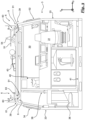
- the transformer 150 can be arranged below the driver's cab 3. In the case of the Figure 1 shown In the case of a central driver's cab locomotive 1, the transformer 150 is fastened in the longitudinal direction L at the bottom center of the frame 101. The transformer 150 is located in the longitudinal direction L between the chassis 105a and 105b.
- a main switch 53 is provided for optionally disconnecting or connecting the current collector 52 from the overhead line.
- the current collector 52 and the main switch 53 are optionally arranged as roof structures 5 on the driver's cab 3.
- the driver's cab 3 of the locomotive 1 shown here is arranged asymmetrically offset from the center of the frame 101 in the longitudinal direction L.
- the driver's cab 3 extends above a part of the rear chassis 105b and a part of the transformer 150.
- the driver's cab 3 has an entry door 38 at its front and rear, which leads to a corridor 103a, 103b on the frame 101, which extends in the longitudinal direction L.
- the front corridor 103a leads in the transverse direction Q along the side next to the supply modules 111, 121.
- the rear corridor 103b leads in the transverse direction Q along the side next to a structure, which can include, for example, an air conditioning system 107 for controlling the temperature of the driver's cab 3.
- the electrical roof structures 5 arranged on the driver's cab 3 can comprise antennas 54.
- the antennas 54 are arranged on antenna supports 51.
- the antenna 54 can be, for example, a GSMR antenna, an antenna for radio remote control, an antenna for diagnostics, a train radio antenna, a train protection antenna and/or a power consumption measuring antenna.
- protective screens 6 are arranged on the upper side of the driver's cab 3.
- the roof structures 5 are located between these protective screens 6 in the transverse direction Q.
- the protective screens 6 can extend on the upper side in the longitudinal direction L essentially completely along the longitudinal edge of the driver's cab 3.
- Fig.3 shows a vertical section through the driver's cab 3 looking forward in the direction of travel.
- the driver's cab 3 has windscreens 30 aligned in the longitudinal direction L in the forward and rearward directions of travel.
- the driver's cab 3 has several side windows 32, 34 formed in its side wall 33.
- the structures on the frame 101 extend in the vertical direction approximately at the level of the lower edge of the side windows 32, 34 and/or the windshield 30 in order to allow the driver as unobstructed a view of the surroundings as possible.
- a driver's cab 31 is arranged in the driver's cab 3, where a train driver can sit or stand and control the locomotive 1.
- a windshield 30 is arranged above the driver's cab 31 on the front wall 40 of the driver's cab 3. Through the windshield 30, the train driver can look out of the driver's cab 31 in the longitudinal direction L onto the tracks and surroundings.
- An entrance door 38 is arranged to the left of the driver's cab 31. The driver can enter the driver's cab 3 from the bridge 103a, 103b of the locomotive 1 through the entrance door 38.
- a standing place or seat 36 can be provided, for example by a folding seat.
- the sectional view shown shows the left and right longitudinal edge 39, which are formed in the transition between one of the side walls 33 opposite in the transverse direction Q and the roof 43 of the driver's cab 3.
- the protective panels 6 are arranged along the longitudinal edge 39.
- the protective panels 6 are detachably attached to the driver's cab 3.
- a vertical distance is formed between a protective panel 6, for example the left one, and the longitudinal edge 39 assigned to it, which is realized here by an air gap 61.
- the protective screens 6 are composed of several protective screen parts in the longitudinal direction.
- the protective screens 6 have flat screen sections 60.
- the screen sections 60 define a plane which is aligned with respect to the vertical direction V with an inclination ⁇ in the transverse direction Q.
- the protective screens 6 are inclined inwards towards one another in the transverse direction Q.
- the inclination ⁇ is approximately 45°.
- the screen sections 60 cover a partial area of the roof 43.
- the screens 6 are located exclusively in the area spanned by the driver's cab 3, in particular the roof 43.
- the protective screens 6 do not protrude outwards beyond the driver's cab 3, in particular not beyond the roof 43.
- the protective screens 6 have a vertical height above the roof 43.
- the vertical height of the protective screens 6 is preferably in the range between 5 cm and 50 cm, preferably in the range 10 cm to 30 cm.
- the protective panels 6 are each connected to the roof 43 of the driver's cab by a mounting structure 9. 3.
- the mounting structures 9 each comprise a double-track rail structure 91.
- the tracks or strips of the rail structure 91 extend parallel to one another in the longitudinal direction L and are arranged offset from one another in the transverse direction Q, the offset preferably being in the range of 10 cm to 30 cm.
- the protective panels 6 have fastening brackets 63 which cooperate with the rail structure 91.
- the fastening brackets 93 extend essentially horizontally in the transverse direction Q vertically below the panel sections 60.
- the fastening brackets 63 can sit on the rail structure 91 and be coupled to the rail structure 91 with fastening means (not shown in detail).
- the fastening means have a pre-assembly state in which they loosely couple the protective panels 6 to the mounting structure 9 so that the protective panels 6 are movable along the mounting structure 9, i.e. in the example shown here they can move forwards and/or backwards along the rail structure 91 in the longitudinal direction L.
- the fastening means When the fastening means are in an assembled state, they create a fixed connection of the protective panels 6 to the mounting structure 9 and thus to the driver's cab 3.
- the mounting structure 9, in particular the rail structure 91 can have run-outs that protrude in the longitudinal direction L beyond the driver's cab 3.
- Electrical roof structures 5, such as antenna supports 51, can also be attached to the locomotive 1 by means of the mounting structure 9 (or alternatively another mounting structure not shown). By arranging the roof structures 5 on a mounting structure 9, their vertical distance from the driver's cab floor 41 can be increased and thus increased protection for the locomotive driver can be ensured. It can be preferred that antenna supports 51 or other roof structures are firmly, in particular non-detachably, connected to a protective panel part.
- An antenna carrier 51 can generally be realized by a substantially flat, horizontal, flat support plate.
- a support plate of an antenna carrier 51 can have a surface with a width and/or length in the range of 10 cm to 150 cm, preferably in the range of 50 cm to 100 cm.
- An antenna carrier 51 comprises a holder for an antenna 54.
- To mount an antenna 54 an antenna carrier 51 can first be positioned and fastened to the driver's cab 3 by means of the mounting structure 9 and then covered with an antenna 54.
- the antenna carriers 51 are arranged at a vertical distance above the roof 43.
- the antenna carrier vertical distance is preferably in the range of 10 cm to 50 cm, in particular in the range of 20 cm to 30 cm. It may be preferred that the vertical distance of an antenna carrier 51 corresponds to the vertical height of a adjacent or connected protective cover 6.
- Figure 4 shows a perspective view of a driver's cab 3.
- four antenna supports 51 offset in the longitudinal direction and three pure protective screens 6 arranged between the antenna supports 51 are arranged by means of a support structure 9.
- a protective screen 6 is arranged and only at the rear end a single antenna support 51 is arranged.
- the antenna supports 51 can be firmly connected to supporting protective screen parts.
- Fastening brackets 63 connect the antenna supports 51 and protective screen parts to the support structure 9.
- the support plates of the antenna supports 51 and the antennas 54 arranged on them are located in the transverse direction Q between the right and the left protective screen 6.
- Figure 5 shows another perspective view of a cab 3.
- Electrical roof structures 5 are shown in the form of a current collector 52 and a main switch 53, which are located in the transverse direction Q between the right and left protective panels 6.
Landscapes
- Engineering & Computer Science (AREA)
- Mechanical Engineering (AREA)
- Transportation (AREA)
- Power Engineering (AREA)
- Life Sciences & Earth Sciences (AREA)
- Wood Science & Technology (AREA)
- Electric Propulsion And Braking For Vehicles (AREA)
Applications Claiming Priority (1)
| Application Number | Priority Date | Filing Date | Title |
|---|---|---|---|
| DE102022123965.9A DE102022123965A1 (de) | 2022-09-19 | 2022-09-19 | Mittelführerhauslokomotive mit einem Führerhaus und mehreren auf dem Führerhaus angeordneten elektrischen Dachaufbauten |
Publications (2)
| Publication Number | Publication Date |
|---|---|
| EP4349681A2 true EP4349681A2 (fr) | 2024-04-10 |
| EP4349681A3 EP4349681A3 (fr) | 2024-07-24 |
Family
ID=88197286
Family Applications (1)
| Application Number | Title | Priority Date | Filing Date |
|---|---|---|---|
| EP23198215.8A Pending EP4349681A3 (fr) | 2022-09-19 | 2023-09-19 | Locomotive avec cabine centrale et plusieurs superstructures électriques de toit placées sur la cabine |
Country Status (2)
| Country | Link |
|---|---|
| EP (1) | EP4349681A3 (fr) |
| DE (1) | DE102022123965A1 (fr) |
Families Citing this family (1)
| Publication number | Priority date | Publication date | Assignee | Title |
|---|---|---|---|---|
| DE102024202863A1 (de) | 2024-03-26 | 2025-10-02 | Siemens Mobility GmbH | Anordnung zum Schutz einer Person vor einem elektrischen Kontakt |
Citations (2)
| Publication number | Priority date | Publication date | Assignee | Title |
|---|---|---|---|---|
| EP1926648B1 (fr) | 2005-09-16 | 2010-01-06 | Bombardier Transportation GmbH | Construction d'une locomotive |
| DE102010035903A1 (de) | 2010-08-26 | 2012-03-01 | Alstom Transport Sa | Schienenfahrzeug |
Family Cites Families (8)
| Publication number | Priority date | Publication date | Assignee | Title |
|---|---|---|---|---|
| AT107367B (de) * | 1926-07-05 | 1927-10-10 | Siemens Schuckertwerke Wien | Einrichtung zur Überwachung der Fahrleitungsspannung. |
| DE29613541U1 (de) | 1996-08-05 | 1997-06-05 | Siemens AG, 80333 München | Schienenfahrzeug |
| DE102008053718A1 (de) | 2008-09-23 | 2010-04-29 | Schalker Eisenhütte Maschinenfabrik Gmbh | Lokomotive |
| FR2976890B1 (fr) * | 2011-06-21 | 2013-08-02 | Sncf | Capot pour toiture d'un vehicule ferroviaire adapte aux communications radioelectriques et vehicule ferroviaire correspondant |
| CN202944337U (zh) * | 2012-11-26 | 2013-05-22 | 湘电重型装备有限公司 | 一种架线式交流变频调速窄轨工矿电机车 |
| WO2015118571A1 (fr) | 2014-02-05 | 2015-08-13 | 川崎重工業株式会社 | Carrosserie de véhicule ferroviaire |
| US20160240928A1 (en) * | 2015-02-12 | 2016-08-18 | Alstom Transport Technologies | Protection for wireless links at train carriage rooftops against jamming and interference |
| DE202019001468U1 (de) | 2019-03-28 | 2019-04-25 | Siemens Mobility GmbH | Schienenfahrzeugwagen mit Dachantennenanordnung |
-
2022
- 2022-09-19 DE DE102022123965.9A patent/DE102022123965A1/de active Pending
-
2023
- 2023-09-19 EP EP23198215.8A patent/EP4349681A3/fr active Pending
Patent Citations (2)
| Publication number | Priority date | Publication date | Assignee | Title |
|---|---|---|---|---|
| EP1926648B1 (fr) | 2005-09-16 | 2010-01-06 | Bombardier Transportation GmbH | Construction d'une locomotive |
| DE102010035903A1 (de) | 2010-08-26 | 2012-03-01 | Alstom Transport Sa | Schienenfahrzeug |
Also Published As
| Publication number | Publication date |
|---|---|
| DE102022123965A1 (de) | 2024-03-21 |
| EP4349681A3 (fr) | 2024-07-24 |
| DE102022123965A8 (de) | 2024-05-16 |
Similar Documents
| Publication | Publication Date | Title |
|---|---|---|
| DE102012005902B4 (de) | Hochspannungskabel-Führungsstruktur für ein elektrisch angetriebenes Fahrzeug | |
| DE102013202236B4 (de) | Schienenfahrzeug | |
| DE102019107504A1 (de) | Energiespeicher für einen Kraftwagen | |
| DE102018132255A1 (de) | Energiespeicher-Bodengruppe für einen Kraftwagenrohbau | |
| EP1238881B1 (fr) | Véhicule sur rails à propulsion autonome, en particulier pour le transport de passagers dans le trafic urbain et régional | |
| EP2303623B1 (fr) | Module de toit | |
| DE3118055C2 (fr) | ||
| EP4349681A2 (fr) | Locomotive avec cabine centrale et plusieurs superstructures électriques de toit placées sur la cabine | |
| DE102018110907A1 (de) | Hängetransportsystem | |
| DE102009050921A1 (de) | Spurgebundenes Fahrzeug mit zumindest einem Energiespeichermodul sowie Verfahren zum Einbau zumindest eines Energiespeichermoduls in ein spurgebundenes Fahrzeug | |
| DE102004056439A1 (de) | Vorrichtung zur Übertragung elektrischer Energie vom Fahrweg auf das Fahrzeug einer Magnetschwebebahn | |
| EP2794381B1 (fr) | Dispositif de commutation pour un véhicule à propulsion électrique et véhicule électrique | |
| EP4143071B1 (fr) | Voiture de véhicule ferroviaire comprenant un toit doté d'une région de toit plate et d'une région surélevée | |
| DE102021127621A1 (de) | Crashstruktur für Energiespeicher | |
| DE102022209456B3 (de) | Schienenfahrzeug | |
| EP4169754B1 (fr) | Structure de collision revêtue pour accumulateur d'énergie | |
| DE102013210333A1 (de) | Fahrzeug, insbesondere Schienenfahrzeug | |
| EP4450358A1 (fr) | Ensemble de réception pour un conteneur pour un véhicule ferroviaire | |
| DE102022123984B4 (de) | Mittelführerhauslokomotive | |
| CH715677A1 (de) | Fahrzeug, insbesondere Bus zur Personenbeförderung, umfassend einen elektrischen Antrieb. | |
| EP4349683A2 (fr) | Locomotive avec cabine de pilotage centrale et au moins une armoire électrique disposée à l'intérieur de la cabine | |
| DE10160290A1 (de) | E-Anlage eines Kraftfahrzeuges | |
| DE102021127612A1 (de) | Seitenverkleidung und Crashstruktur für Energiespeicher eines Kraftfahrzeugs | |
| EP2218623A2 (fr) | Locomotive avec deux unités de traction supperposées | |
| DE20103801U1 (de) | Angetriebenes Schienenfahrzeug, insbesondere für die Personenbeförderung im Nah- und Regionalverkehr |
Legal Events
| Date | Code | Title | Description |
|---|---|---|---|
| PUAI | Public reference made under article 153(3) epc to a published international application that has entered the european phase |
Free format text: ORIGINAL CODE: 0009012 |
|
| STAA | Information on the status of an ep patent application or granted ep patent |
Free format text: STATUS: THE APPLICATION HAS BEEN PUBLISHED |
|
| AK | Designated contracting states |
Kind code of ref document: A2 Designated state(s): AL AT BE BG CH CY CZ DE DK EE ES FI FR GB GR HR HU IE IS IT LI LT LU LV MC ME MK MT NL NO PL PT RO RS SE SI SK SM TR |
|
| PUAL | Search report despatched |
Free format text: ORIGINAL CODE: 0009013 |
|
| AK | Designated contracting states |
Kind code of ref document: A3 Designated state(s): AL AT BE BG CH CY CZ DE DK EE ES FI FR GB GR HR HU IE IS IT LI LT LU LV MC ME MK MT NL NO PL PT RO RS SE SI SK SM TR |
|
| RIC1 | Information provided on ipc code assigned before grant |
Ipc: B60L 5/00 20060101ALI20240614BHEP Ipc: B61D 17/12 20060101ALI20240614BHEP Ipc: B61C 3/00 20060101AFI20240614BHEP |
|
| STAA | Information on the status of an ep patent application or granted ep patent |
Free format text: STATUS: REQUEST FOR EXAMINATION WAS MADE |
|
| 17P | Request for examination filed |
Effective date: 20250122 |