EP4169770A1 - Regal eines warentransportfachs - Google Patents
Regal eines warentransportfachs Download PDFInfo
- Publication number
- EP4169770A1 EP4169770A1 EP22201476.3A EP22201476A EP4169770A1 EP 4169770 A1 EP4169770 A1 EP 4169770A1 EP 22201476 A EP22201476 A EP 22201476A EP 4169770 A1 EP4169770 A1 EP 4169770A1
- Authority
- EP
- European Patent Office
- Prior art keywords
- shelf
- arm
- compartment
- arms
- sections
- Prior art date
- Legal status (The legal status is an assumption and is not a legal conclusion. Google has not performed a legal analysis and makes no representation as to the accuracy of the status listed.)
- Granted
Links
Images


Classifications
-
- B—PERFORMING OPERATIONS; TRANSPORTING
- B60—VEHICLES IN GENERAL
- B60P—VEHICLES ADAPTED FOR LOAD TRANSPORTATION OR TO TRANSPORT, TO CARRY, OR TO COMPRISE SPECIAL LOADS OR OBJECTS
- B60P3/00—Vehicles adapted to transport, to carry or to comprise special loads or objects
- B60P3/007—Vehicles adapted to transport, to carry or to comprise special loads or objects for delivery of small articles, e.g. milk, frozen articles
-
- A—HUMAN NECESSITIES
- A47—FURNITURE; DOMESTIC ARTICLES OR APPLIANCES; COFFEE MILLS; SPICE MILLS; SUCTION CLEANERS IN GENERAL
- A47B—TABLES; DESKS; OFFICE FURNITURE; CABINETS; DRAWERS; GENERAL DETAILS OF FURNITURE
- A47B96/00—Details of cabinets, racks or shelf units not covered by a single one of groups A47B43/00 - A47B95/00; General details of furniture
- A47B96/02—Shelves
- A47B96/027—Cantilever shelves
- A47B96/028—Cantilever shelves characterised by support bracket location means, e.g. fixing means between support bracket and shelf
-
- B—PERFORMING OPERATIONS; TRANSPORTING
- B60—VEHICLES IN GENERAL
- B60P—VEHICLES ADAPTED FOR LOAD TRANSPORTATION OR TO TRANSPORT, TO CARRY, OR TO COMPRISE SPECIAL LOADS OR OBJECTS
- B60P7/00—Securing or covering of load on vehicles
- B60P7/06—Securing of load
- B60P7/08—Securing to the vehicle floor or sides
Definitions
- the invention relates to fittings for land vehicles, and more particularly to shelves for goods transported by these vehicles.
- Vans are an example of land vehicles equipped with a compartment that allows the transport of more or less voluminous goods.
- the goods can be stored in the compartment thanks to shelves which facilitate access to the goods and which allow the goods positioned at the bottom not to be crushed by the goods positioned above.
- These shelves are generally fixed to a vertical partition of the compartment.
- Known compartment shelves comprise at least two arms arranged cantilevered, substantially perpendicular to said partition or forming an acute upward angle with said partition.
- These shelves also comprise sections placed on a side of the arms, preferably substantially perpendicular to a direction of elongation of the arms, and secured to the latter. The transported goods can thus be placed on the profiles.
- the shelves generally include raised edges arranged around the periphery of all the sections. These raised borders limit the risk of movement or even of the goods placed on such shelves falling and therefore limit the risk of deterioration of the goods.
- the profiles are arranged on the arm, providing a space between each of them.
- the spacers are positioned on the arms from above.
- Each intermediate piece is fixed to said face of one of the arms by means of immobilization such as, for example, a rivet.
- the spacers comprise positioning flanks configured to come into contact with edges of said panel in order to correctly position the spacers in relation to the pan.
- the spacers also include a hole allowing an operator to pierce the arm at a predefined location to insert the rivet therein.
- the sections comprise lateral flanges extending on either side of the sections towards the neighboring sections.
- the spacers are configured so that the side flanges of the sections are positioned between the spacers and the arms in order to press and hold the sections against the arms.
- the assembly of such shelves includes fixing the arms to a vertical partition of a goods transport compartment.
- the assembly also includes an approximate positioning of the profiles on the arms.
- the assembly then includes a positioning of the spacers between the profiles and a final positioning of the profiles against the spacers.
- the assembly comprises, after the final positioning of the sections, a drilling of each arm at the level of each intermediate piece then a riveting of each intermediate piece to the arms.
- the number of arms and sections and the length of the sections of these shelves can be personalized according to the constraints of the end user and the dimensions of the compartment.
- these shelves must be assembled directly in the compartment or close to it and it is very complicated to provide automatic pre-assembly as the final configurations of the shelves are varied.
- the object of the invention is to propose a shelf for a goods transport compartment allowing rapid assembly of the shelf whatever the final configuration of the shelf required by the constraints of the end user and of the compartment.
- a shelf of a goods transport compartment comprising at least two arms, each arm comprising a means for fixing the arm substantially horizontally and cantilevered to a partition of the compartment, the shelf comprising, supported by the arms, sections forming a support surface for the goods, the shelf comprising, for each arm, intermediate pieces for holding the sections to the arm, the sections being arranged between the pieces spacers and comprising side wings pressed against and held against the arm by the spacer pieces.
- Such a shelf allows the support and storage of goods in a cargo transport compartment.
- the profiles are spaced from each other by means of spacers.
- the spacing between the sections is adjusted by the spacers, which makes it easy and quick for an operator to position the sections.
- the wings of the sections located between the spacers and the arm allow the sections to be held against the arm without the need to fix the sections directly to the arm.
- the spacers are positioned with respect to the arm at least thanks to the profiles.
- the operator can thus easily and quickly position these parts relative to the arm.
- an operator can securely attach the spacers to the arm.
- the fixing is for example made by drilling these parts and the arm then by riveting but the invention makes it possible to obtain a particularly simple fixing.
- intermediate pieces arranged for the same arm are integrated into a slide having a shape complementary to a guide of said arm.
- the slide keeps the spacers on the arm.
- the fixing of a single spacer piece per arm thus makes it possible to block the sliding of the slide on the guides.
- a method for mounting a goods transport compartment shelf comprising securing at least two arms to a partition of the compartment, the arms extending substantially horizontally and bearing -overhanging the partition, the method comprising a positioning of the sections of the shelf supported by the arms, a positioning of spacers of the shelf between the sections, the process also comprising a plating of the side flanges of the sections against the arm by the spacers, spacers arranged for the same arm being integrated into a slide having a shape complementary to a guide of said arm, the method comprises sliding the slide on the guide.
- FIG. 1 represents a van comprising a compartment 1 comprising a shelf 2 according to one embodiment of the invention, intended to support goods for their transport.
- the shelf 2 is fixed to a vertical partition 11 of the compartment 1.
- shelf 2 can also be attached to a truck, a car, a trailer or any land vehicle for transporting goods comprising a substantially vertical partition 11.
- the shelf 2 comprises at least two arms 21 arranged cantilevered and substantially perpendicular to the vertical partition 11 on which the shelf 2 is fixed.
- the arm 21 comprises a folding means 212 disposed, preferably, close to the vertical partition 11 and configured to arrange the shelf 2 in a position substantially parallel to the vertical partition 11 or in a substantially perpendicular position. to the vertical partition 11.
- a folding means 212 disposed, preferably, close to the vertical partition 11 and configured to arrange the shelf 2 in a position substantially parallel to the vertical partition 11 or in a substantially perpendicular position. to the vertical partition 11.
- the shelf 2 comprises, for each arm 21, a rail 22 on which the arm 21 is fixed.
- the rail 22 is fixed to said vertical partition 11.
- the rails 22 allow a movement of the arms 21 substantially vertically.
- the height of the shelf 2 can be modified without having, for example, the need to drill new holes in the vertical partition 11 .
- the shelf 2 also comprises, according to the embodiment shown, sections 23 placed on a panel 214 of the arms 21, substantially perpendicular to the arms 21 and substantially parallel to the vertical partition 11.
- each arm 21 comprises a core 215 substantially perpendicular to the face 214 of the arms 21 extending opposite the sections 23.
- the arms 21 are made of metallic material. According to one embodiment, the arms 21 are made of aluminum alloy.
- the arms 21 are made by molding.
- the arms 21 have a shape that flares out longitudinally towards the partition 11.
- the shelf 2 comprises, for each arm 21, a strip 24 for assembling and holding the sections 23 on the arms 21.
- the strip 24 has a flaring shape complementary to the shape of the arm 21.
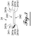
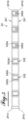
- THE figures 2 to 7 more particularly represent the strip 24 for assembling and holding the profiles 23.
- the strip 24 has an elongated shape.
- the strip 24 comprises a slide 241 substantially parallel to the elongation dimension of the strip 24.
- the slide 241 comprises, on either side of the intermediate parts (242), an intermediate flank 241a and two end hooks 241b.
- the intermediate flank 241a is integral at its two ends with one end of each end hook 241b.
- Each extreme off-hook 241b thus comprises an end not in contact with the intermediate flank 241a hereinafter called the end end 241b1.
- the two extreme hooks 241b are substantially perpendicular to the intermediate side 241a and extend in the same direction.
- the strip 24 also comprises spacer pieces 242 integral with the end end 241b1 of one of the end hooks 241b of the slide 241 so that the end ends 241b1 of the end hooks 241b of the slide 241 substantially face each other.
- the slide 241 thus forms a groove 243 having, in section, substantially a T-shape, particularly visible on the picture 3 .
- the spacer pieces 242 are distributed substantially equidistantly over the length of the slide 241.
- the slide 241 includes, at each intermediate part 242, a cutout 241b2 of its end hooks 241b not in contact with the intermediate parts 242. According to the embodiment shown, these cutouts 241b2 are substantially the width of the spacer pieces 242.
- the spacer pieces 242 comprise a main body 242a having a substantially parallelepipedic shape.
- the main body 242a secures the intermediate parts 242 to the slide 241.
- Each spacer piece 242 comprises two fins 242b arranged on either side of the main body 242a.
- the fins 242b protrude from the main body 242a towards the adjacent spacer pieces 242.
- the strip 24 comprises, between the spacer pieces 242, notches 244 passing through the extreme hooks 241b of the slide 241 secured to the spacer pieces 242 and partly crossing the fins 242b.
- the notches 244 are configured so that the side of the fins 242b facing the slide 241 is further from the slide 241 than the side of the main body 242a facing the slide 241.
- the notches 244 thus define a substantially T-shaped passage, particularly visible on the figure 2 .
- the main body 242a of each intermediate piece 242 comprises a recess 242a1 on the side of the main body 242a oriented towards the slide 241.
- the recess 242a1 has a substantially parallelepipedic shape.
- the recess 242a1 is substantially centered with respect to the main body 242a.
- At least one of the spacer pieces 242 is not in contact with the arm 21 once the slide 241 has slid over the arm 21.
- the friction between the strip 24 and the arm 21 is reduced. when sliding the strip 24 on the arm 21.
- the strip 24 comprises, at a first end 241c of the slide 241, an intermediate half-piece 242.
- the cavities 242c are arranged on the main body 242a of the intermediate pieces 242, on the side opposite the slideway 241.
- the cavity 242c is a hole passing through the main body 242a of the intermediate pieces 242.
- the intermediate assembly and holding parts 242 comprising a cavity 242c each comprise a support stud 242d.
- the support stud 242d protrudes from the recess 242a1 as far as the level of the side of the main body 242a oriented towards the slide 241.
- the support pad 242d is substantially aligned with the cavity 242c.
- the support stud 241d protrudes from the side of the main body 242a oriented towards the arm 21 but distant from the arm 21.
- the slide 241 comprises at least one weakened part.
- This weakened part makes it possible to easily cut the strip 24 for assembly and maintenance in order to reduce its length according to the configuration required for the shelf 2.
- the strip 24 is thus easily frangible at predetermined places.
- the strip 24 is made of plastic material or resin.
- the strip 24 is manufactured by molding.
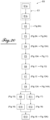
- a method E0 for mounting the shelf 2 comprises securing E1 of at least two arms 21 to the vertical partition 11 of the compartment 1.
- the attachment E1 of the arms 21 comprises an attachment E1a of the rails 22 to the vertical partition 11 and an attachment E1b of each arm 21 to one of the rails 22.
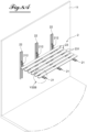
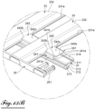
- the method E0 for mounting the shelf 2 comprises, as shown in figure 8A And 8B , a pose E2 upside down sections 23.
- the sections 23 are arranged substantially parallel to each other and slightly spaced from each other.
- Each profile 23 comprises a face 231 for laying against the arms 21 facing upwards when laying E2 upside down.
- the sections 23 have in section a quadrilateral shape whose laying face 231 and its opposite face 232 are substantially parallel to each other.
- the sections 23 provide a substantially flat area for placing the goods to be transported there.
- the laying face 231 comprises lateral flanges 231a which protrude from the quadrilateral formed by the sections 23 in alignment with this laying face 231.
- the assembly method E0 comprises an attachment E3 of a side edge 25 of the shelf 2 to the profiles 23.
- the attachment E3 of the side edge 25 is made by fitting the side edge 25 into the sections 23.
- the assembly process E0 includes an engagement E4 then a sliding E4 of strips 24 on the sections 23.
- the engagement E4 is carried out for all the strips 24 then the sliding E5 of the strips 24 is carried out for all the strips 24 engaged.
- the engagement E4 and the sliding E5 is carried out for each strip 24, one by one.
- the engagement E4 is made by inserting the laying face 231 of the sections 23 into the notches 244 of the strips 24.
- the wings 231a of the laying face 231 of the sections 23 are configured to be inserted between the fins 242b and the slide 241 rulers 24.
- the spacing between the sections 23 is configured by the intermediate parts 242.
- the sections 23 and the strips 24 are secured together by a slide connection substantially parallel to the extension dimension of the sections 23.
- the sliding E5 of the strips 24 on the sections 23 makes it possible to place approximately each strip 24 at the level of each arm 21.
- the laying E2 upside down of the sections 23 is carried out on the arms 21 secured to the vertical partition 11.
- the positioning of the strips 24 at the level of each arm 21 is facilitated during the sliding E5 of the strips.
- Laying E2 upside down also facilitates the sliding E5 of the strips 24 so as not to impose a lifting of the profiles 23 during the sliding E5 of the strips 24.
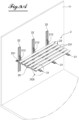
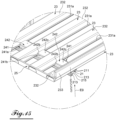
- the assembly process E0 comprises, as shown in figure 12 , a reversal E6 of the assembly formed by the sections 23 and the strips 24.
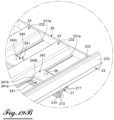
- the method E0 of mounting the shelf 2 comprises, after assembly of the sections 23 and the strips 24, a sliding E7 of this assembly on the arms 21, as shown in the figures 13A And 13B .
- each arm 21 comprises a guide 211 having in section a shape complementary to the shape of the grooves 243 of the strips 24.
- the groove 243 of each strip 24 is engaged and slid on the guide 211 of one of the arms 21.
- the end 241b1 of the end of the extreme hooks 241b of the slide 241 opposite the intermediate pieces 242 is engaged by passages 213 of said arm 21 arranged at one end of said arm 21 opposite the vertical partition 11 .
- the recess 242a1 provided in the intermediate parts 242 limits the contact between the strips 24 and the arms 21.
- the friction between the strips 24 and the arms 21 is limited and the sliding E7 of the assembly of the strips 24 and the sections 23 on the arms 21 is facilitated.
- the intermediate half-piece 242 of the strips 24 is, after sliding E7 of the assembly of the strips 24 and the sections 23 on the arms 21, positioned on the side of the vertical partition 11.
- the section 23 closest to the vertical partition 11 thus limits the space between this section 23 and the vertical partition 11, limiting the risk of goods falling on the shelf 2.
- the side edge 25 of the shelf 2 comprises, after sliding E7 of said assembly on the arms 21, a fixing means 251 for a profile 23 not used.
- This unused fixing means 251 is arranged at the end of the arm 21 opposite the vertical partition 11.
- the method E0 of mounting the shelf 2, after sliding E7 of said assembly on the arms 21, comprises securing E8 of a profile 23 to the means 251 of unused fastening.
- the attachment E8 of the profile 23 is made by interlocking the profile 23 on the means 251 for fixing the side edge 25 .
- this last profile 23 fixed comprises a protective edge 233 projecting upwards, when the shelf 2 is in position to support goods, in order to limit the risk of movement and/or falling of the goods placed on the shelf 2.
- the side edge 25 also comprises a protective edge projecting upwards, when the shelf 2 is in position to support goods, in order to limit the risk of movement and/or falling of the goods. goods arranged on the shelf 2.
- the assembly process E0 includes a hole E9 of the last assembled profile 23 and of the guide 211.
- This hole E9 is preferably made at the level of each arm 21.
- the assembly process E0 includes an E10 attachment of the last profile 23 assembled with the guide 211.
- This E10 attachment is for example made using a rivet 26.
- This E10 attachment is preferably made at each previously drilled hole.
- the core 215 of the arms 21 is not centered with respect to the face 214 of the arms 21 so as to leave enough space for the hole E9 and the fixing E10.
- This hole E9 is preferably made from below so that the rivet 26 or any other means of immobilization does not protrude from the face 231 of the profile 23 on which the goods will be placed.
- the means for immobilizing the intermediate part 242 is for example a screw, a bolt, glue, a weld or else a cooperation between a lug and a hollow.
- the mounting method E0 includes a hole E11 of one of the strips 24 and of the guide 211. This hole E11 is preferably made at the level of each arm 21.
- the cavities 242c of the intermediate pieces 242 facilitate the drilling E11 of the strips 24 and of the guide 211 by making it possible to center a drilling means more easily and quickly.
- the assembly process E0 includes an E12 attachment of the strip 24 with the guide 211.
- This E12 attachment is for example made using a rivet 26.
- This E12 attachment is preferably made at each previously drilled hole.
- the upper face of the strip 24 is preferably lower than the face 231 for laying the profiles 23.
- This hole E11 can thus be made from above so as to facilitate handling without the rivet 26 or any other means of immobilization protrudes from the face 231 of the profile 23 on which the goods will be placed.
- the support stud 242d When fixing E12 of the strip 24 with the guide 211, the support stud 242d is in contact with the guide 211. Thus, the intermediate piece 242 does not deform under the effect of the rivet 26 or any other means. immobilization.
- the mounting method E0 comprises fixing E13 of a second lateral edge 25, opposite to the first lateral edge 25 .
- the sections 23 are made of metallic material. According to one embodiment, the sections 23 are made of aluminum alloy.
- the profiles 23 are manufactured by extrusion.
- the shelf 2 according to the invention thus makes it possible to facilitate the classification and access to the goods.
- the shelf 2 also makes it possible to block the movement of the goods placed on the shelf 2 with respect to the compartment 1 and therefore to reduce the risk of deterioration of these goods.
- the strips 24 according to the invention thus make it possible to considerably reduce the assembly time by making it possible not to fix each intermediate part 242 to the arms 21.
- the assembly of such a shelf 2 is facilitated since the strips 24 maintain the spacer pieces 242 and the sections 23 to each other, which allows the operator to manipulate only an integral assembly.
- strips 24 allow quick and easy customization of the shelf 2 according to the constraints of the customer and the compartment 1 in which it is fixed.
Landscapes
- Engineering & Computer Science (AREA)
- Transportation (AREA)
- Mechanical Engineering (AREA)
- Health & Medical Sciences (AREA)
- Public Health (AREA)
- Assembled Shelves (AREA)
- Handcart (AREA)
- Connection Of Plates (AREA)
Applications Claiming Priority (1)
| Application Number | Priority Date | Filing Date | Title |
|---|---|---|---|
| FR2111145A FR3128106B1 (fr) | 2021-10-20 | 2021-10-20 | Etagère d’un compartiment de transport de marchandises |
Publications (3)
| Publication Number | Publication Date |
|---|---|
| EP4169770A1 true EP4169770A1 (de) | 2023-04-26 |
| EP4169770B1 EP4169770B1 (de) | 2024-06-05 |
| EP4169770C0 EP4169770C0 (de) | 2024-06-05 |
Family
ID=79602039
Family Applications (1)
| Application Number | Title | Priority Date | Filing Date |
|---|---|---|---|
| EP22201476.3A Active EP4169770B1 (de) | 2021-10-20 | 2022-10-13 | Regal eines warentransportfachs |
Country Status (4)
| Country | Link |
|---|---|
| EP (1) | EP4169770B1 (de) |
| ES (1) | ES2988897T3 (de) |
| FR (1) | FR3128106B1 (de) |
| PL (1) | PL4169770T3 (de) |
Citations (5)
| Publication number | Priority date | Publication date | Assignee | Title |
|---|---|---|---|---|
| US3233852A (en) * | 1965-03-15 | 1966-02-08 | Raymond J Azar | Supporting shelf assembly |
| US20010035114A1 (en) * | 2000-03-15 | 2001-11-01 | Ash David L. | Stowable shelf assembly |
| US20190053642A1 (en) * | 2013-10-01 | 2019-02-21 | Spg International Llc | Shelving system |
| EP3750444A1 (de) * | 2019-06-11 | 2020-12-16 | Avraham Y. Levi | Faltbare regalkonstruktion |
| US20210009041A1 (en) * | 2019-07-11 | 2021-01-14 | Adrian Steel Company | Vehicle shelf system & method of use |
-
2021
- 2021-10-20 FR FR2111145A patent/FR3128106B1/fr active Active
-
2022
- 2022-10-13 EP EP22201476.3A patent/EP4169770B1/de active Active
- 2022-10-13 PL PL22201476.3T patent/PL4169770T3/pl unknown
- 2022-10-13 ES ES22201476T patent/ES2988897T3/es active Active
Patent Citations (5)
| Publication number | Priority date | Publication date | Assignee | Title |
|---|---|---|---|---|
| US3233852A (en) * | 1965-03-15 | 1966-02-08 | Raymond J Azar | Supporting shelf assembly |
| US20010035114A1 (en) * | 2000-03-15 | 2001-11-01 | Ash David L. | Stowable shelf assembly |
| US20190053642A1 (en) * | 2013-10-01 | 2019-02-21 | Spg International Llc | Shelving system |
| EP3750444A1 (de) * | 2019-06-11 | 2020-12-16 | Avraham Y. Levi | Faltbare regalkonstruktion |
| US20210009041A1 (en) * | 2019-07-11 | 2021-01-14 | Adrian Steel Company | Vehicle shelf system & method of use |
Also Published As
| Publication number | Publication date |
|---|---|
| EP4169770B1 (de) | 2024-06-05 |
| EP4169770C0 (de) | 2024-06-05 |
| FR3128106A1 (fr) | 2023-04-21 |
| ES2988897T3 (es) | 2024-11-22 |
| FR3128106B1 (fr) | 2023-10-27 |
| PL4169770T3 (pl) | 2024-10-14 |
Similar Documents
| Publication | Publication Date | Title |
|---|---|---|
| EP2115837B1 (de) | Vorrichtung zur befestigung einer garn-kabelbahn | |
| EP1564141B1 (de) | Flugzeugsitzschiene und deren Fertigungsverfahren | |
| EP0451068B1 (de) | Verbindungsstück für längliche Elemente | |
| WO2005005164A2 (fr) | Dispositif apte a realiser la mise sous tension et le maintien d'une toile | |
| EP4169770B1 (de) | Regal eines warentransportfachs | |
| EP4168270A1 (de) | Kraftfahrzeugsitz-befestigungsbügel, der für verschiedene varianten einer fahrzeugreichweite verwendbar ist | |
| EP3323676B1 (de) | Festzurr-anordnung für gegenstände auf einer oberfläche, insbesondere einem ladeboden eines transportfahrzeugs für fracht | |
| EP1283124B1 (de) | Vorrichtung zur Befestigung eines Sitzes auf einem Fahrzeugboden | |
| FR2548002A1 (fr) | Ensemble cremaillere-console perfectionne destine au rangement avec fixation sur parois | |
| FR2699235A1 (fr) | Dispositif de fixation d'un écrou à embase sur une pièce quelconque. | |
| EP1634512B1 (de) | Präsentationsregal zur Lagerung kleiner Lasten zur grossflächigen Verteilung | |
| EP2453540B1 (de) | Universalhalterungssschiene | |
| FR2699897A1 (fr) | Magasin de stockage dynamique. | |
| EP0437134B1 (de) | Käfigmutter zur Blindbefestigung auf einer Platte oder ähnlichem | |
| EP3505779B1 (de) | Metallblechplatte, die eine schraube ohne verschweissung umfasst | |
| FR3158948A1 (fr) | Structure de caisse de carrosserie de véhicule automobile | |
| EP4416395A1 (de) | Anordnung zur befestigung eines an einer stützwand zu befestigenden elements | |
| EP3442852A1 (de) | Anordnung einer abschirmung und eines karosserieelements eines kraftfahrzeugs, insbesondere eines karosserieelements aus blech | |
| FR3155757A1 (fr) | Traverse d’assise destinée à être fixée sur le plancher d’un véhicule automobile | |
| FR3057445B1 (fr) | Structure d'etagere | |
| FR3059925B1 (fr) | Procede de positionnement d'une console centrale au moyen d'un outil de positionnement et outil correspondant | |
| WO2026027407A1 (fr) | Système de fixation sur un grillage en treillis | |
| FR2789453A1 (fr) | Agencement perfectionne pour la fixation d'une glissiere sur un plancher de vehicule automobile | |
| FR3117075A1 (fr) | Support de fixation d’un élément à un plancher de véhicule automobile et assemblage correspondant | |
| EP3835510A1 (de) | Handlaufvorrichtung für geländer |
Legal Events
| Date | Code | Title | Description |
|---|---|---|---|
| PUAI | Public reference made under article 153(3) epc to a published international application that has entered the european phase |
Free format text: ORIGINAL CODE: 0009012 |
|
| STAA | Information on the status of an ep patent application or granted ep patent |
Free format text: STATUS: THE APPLICATION HAS BEEN PUBLISHED |
|
| AK | Designated contracting states |
Kind code of ref document: A1 Designated state(s): AL AT BE BG CH CY CZ DE DK EE ES FI FR GB GR HR HU IE IS IT LI LT LU LV MC ME MK MT NL NO PL PT RO RS SE SI SK SM TR |
|
| P01 | Opt-out of the competence of the unified patent court (upc) registered |
Effective date: 20230518 |
|
| STAA | Information on the status of an ep patent application or granted ep patent |
Free format text: STATUS: REQUEST FOR EXAMINATION WAS MADE |
|
| 17P | Request for examination filed |
Effective date: 20230824 |
|
| RBV | Designated contracting states (corrected) |
Designated state(s): AL AT BE BG CH CY CZ DE DK EE ES FI FR GB GR HR HU IE IS IT LI LT LU LV MC ME MK MT NL NO PL PT RO RS SE SI SK SM TR |
|
| GRAP | Despatch of communication of intention to grant a patent |
Free format text: ORIGINAL CODE: EPIDOSNIGR1 |
|
| STAA | Information on the status of an ep patent application or granted ep patent |
Free format text: STATUS: GRANT OF PATENT IS INTENDED |
|
| INTG | Intention to grant announced |
Effective date: 20240125 |
|
| GRAS | Grant fee paid |
Free format text: ORIGINAL CODE: EPIDOSNIGR3 |
|
| GRAA | (expected) grant |
Free format text: ORIGINAL CODE: 0009210 |
|
| STAA | Information on the status of an ep patent application or granted ep patent |
Free format text: STATUS: THE PATENT HAS BEEN GRANTED |
|
| RAP3 | Party data changed (applicant data changed or rights of an application transferred) |
Owner name: POMMIER |
|
| AK | Designated contracting states |
Kind code of ref document: B1 Designated state(s): AL AT BE BG CH CY CZ DE DK EE ES FI FR GB GR HR HU IE IS IT LI LT LU LV MC ME MK MT NL NO PL PT RO RS SE SI SK SM TR |
|
| REG | Reference to a national code |
Ref country code: CH Ref legal event code: EP |
|
| REG | Reference to a national code |
Ref country code: DE Ref legal event code: R096 Ref document number: 602022003800 Country of ref document: DE |
|
| REG | Reference to a national code |
Ref country code: IE Ref legal event code: FG4D Free format text: LANGUAGE OF EP DOCUMENT: FRENCH |
|
| U01 | Request for unitary effect filed |
Effective date: 20240701 |
|
| U07 | Unitary effect registered |
Designated state(s): AT BE BG DE DK EE FI FR IT LT LU LV MT NL PT SE SI Effective date: 20240709 |
|
| P04 | Withdrawal of opt-out of the competence of the unified patent court (upc) registered |
Free format text: CASE NUMBER: APP_40066/2024 Effective date: 20240705 |
|
| PG25 | Lapsed in a contracting state [announced via postgrant information from national office to epo] |
Ref country code: HR Free format text: LAPSE BECAUSE OF FAILURE TO SUBMIT A TRANSLATION OF THE DESCRIPTION OR TO PAY THE FEE WITHIN THE PRESCRIBED TIME-LIMIT Effective date: 20240605 |
|
| PG25 | Lapsed in a contracting state [announced via postgrant information from national office to epo] |
Ref country code: GR Free format text: LAPSE BECAUSE OF FAILURE TO SUBMIT A TRANSLATION OF THE DESCRIPTION OR TO PAY THE FEE WITHIN THE PRESCRIBED TIME-LIMIT Effective date: 20240906 |
|
| PG25 | Lapsed in a contracting state [announced via postgrant information from national office to epo] |
Ref country code: NO Free format text: LAPSE BECAUSE OF FAILURE TO SUBMIT A TRANSLATION OF THE DESCRIPTION OR TO PAY THE FEE WITHIN THE PRESCRIBED TIME-LIMIT Effective date: 20240905 Ref country code: HR Free format text: LAPSE BECAUSE OF FAILURE TO SUBMIT A TRANSLATION OF THE DESCRIPTION OR TO PAY THE FEE WITHIN THE PRESCRIBED TIME-LIMIT Effective date: 20240605 Ref country code: GR Free format text: LAPSE BECAUSE OF FAILURE TO SUBMIT A TRANSLATION OF THE DESCRIPTION OR TO PAY THE FEE WITHIN THE PRESCRIBED TIME-LIMIT Effective date: 20240906 Ref country code: RS Free format text: LAPSE BECAUSE OF FAILURE TO SUBMIT A TRANSLATION OF THE DESCRIPTION OR TO PAY THE FEE WITHIN THE PRESCRIBED TIME-LIMIT Effective date: 20240905 |
|
| U20 | Renewal fee for the european patent with unitary effect paid |
Year of fee payment: 3 Effective date: 20241007 |
|
| REG | Reference to a national code |
Ref country code: ES Ref legal event code: FG2A Ref document number: 2988897 Country of ref document: ES Kind code of ref document: T3 Effective date: 20241122 |
|
| P05 | Withdrawal of opt-out of the competence of the unified patent court (upc) changed |
Free format text: CASE NUMBER: APP_40066/2024 Effective date: 20240709 |
|
| PG25 | Lapsed in a contracting state [announced via postgrant information from national office to epo] |
Ref country code: IS Free format text: LAPSE BECAUSE OF FAILURE TO SUBMIT A TRANSLATION OF THE DESCRIPTION OR TO PAY THE FEE WITHIN THE PRESCRIBED TIME-LIMIT Effective date: 20241005 |
|
| PG25 | Lapsed in a contracting state [announced via postgrant information from national office to epo] |
Ref country code: CZ Free format text: LAPSE BECAUSE OF FAILURE TO SUBMIT A TRANSLATION OF THE DESCRIPTION OR TO PAY THE FEE WITHIN THE PRESCRIBED TIME-LIMIT Effective date: 20240605 |
|
| PG25 | Lapsed in a contracting state [announced via postgrant information from national office to epo] |
Ref country code: RO Free format text: LAPSE BECAUSE OF FAILURE TO SUBMIT A TRANSLATION OF THE DESCRIPTION OR TO PAY THE FEE WITHIN THE PRESCRIBED TIME-LIMIT Effective date: 20240605 Ref country code: SK Free format text: LAPSE BECAUSE OF FAILURE TO SUBMIT A TRANSLATION OF THE DESCRIPTION OR TO PAY THE FEE WITHIN THE PRESCRIBED TIME-LIMIT Effective date: 20240605 |
|
| PG25 | Lapsed in a contracting state [announced via postgrant information from national office to epo] |
Ref country code: SM Free format text: LAPSE BECAUSE OF FAILURE TO SUBMIT A TRANSLATION OF THE DESCRIPTION OR TO PAY THE FEE WITHIN THE PRESCRIBED TIME-LIMIT Effective date: 20240605 |
|
| PG25 | Lapsed in a contracting state [announced via postgrant information from national office to epo] |
Ref country code: SM Free format text: LAPSE BECAUSE OF FAILURE TO SUBMIT A TRANSLATION OF THE DESCRIPTION OR TO PAY THE FEE WITHIN THE PRESCRIBED TIME-LIMIT Effective date: 20240605 Ref country code: SK Free format text: LAPSE BECAUSE OF FAILURE TO SUBMIT A TRANSLATION OF THE DESCRIPTION OR TO PAY THE FEE WITHIN THE PRESCRIBED TIME-LIMIT Effective date: 20240605 Ref country code: RO Free format text: LAPSE BECAUSE OF FAILURE TO SUBMIT A TRANSLATION OF THE DESCRIPTION OR TO PAY THE FEE WITHIN THE PRESCRIBED TIME-LIMIT Effective date: 20240605 Ref country code: IS Free format text: LAPSE BECAUSE OF FAILURE TO SUBMIT A TRANSLATION OF THE DESCRIPTION OR TO PAY THE FEE WITHIN THE PRESCRIBED TIME-LIMIT Effective date: 20241005 Ref country code: CZ Free format text: LAPSE BECAUSE OF FAILURE TO SUBMIT A TRANSLATION OF THE DESCRIPTION OR TO PAY THE FEE WITHIN THE PRESCRIBED TIME-LIMIT Effective date: 20240605 |
|
| U1N | Appointed representative for the unitary patent procedure changed after the registration of the unitary effect |
Representative=s name: WEINSTEIN SERVICES & CONSEILS; FR |
|
| PLBE | No opposition filed within time limit |
Free format text: ORIGINAL CODE: 0009261 |
|
| STAA | Information on the status of an ep patent application or granted ep patent |
Free format text: STATUS: NO OPPOSITION FILED WITHIN TIME LIMIT |
|
| 26N | No opposition filed |
Effective date: 20250306 |
|
| PG25 | Lapsed in a contracting state [announced via postgrant information from national office to epo] |
Ref country code: MC Free format text: LAPSE BECAUSE OF FAILURE TO SUBMIT A TRANSLATION OF THE DESCRIPTION OR TO PAY THE FEE WITHIN THE PRESCRIBED TIME-LIMIT Effective date: 20240605 |
|
| PGFP | Annual fee paid to national office [announced via postgrant information from national office to epo] |
Ref country code: PL Payment date: 20250925 Year of fee payment: 4 |
|
| PG25 | Lapsed in a contracting state [announced via postgrant information from national office to epo] |
Ref country code: IE Free format text: LAPSE BECAUSE OF NON-PAYMENT OF DUE FEES Effective date: 20241013 |
|
| REG | Reference to a national code |
Ref country code: CH Ref legal event code: U11 Free format text: ST27 STATUS EVENT CODE: U-0-0-U10-U11 (AS PROVIDED BY THE NATIONAL OFFICE) Effective date: 20251101 |
|
| U20 | Renewal fee for the european patent with unitary effect paid |
Year of fee payment: 4 Effective date: 20251006 |
|
| PGFP | Annual fee paid to national office [announced via postgrant information from national office to epo] |
Ref country code: CH Payment date: 20251101 Year of fee payment: 4 |
|
| PG25 | Lapsed in a contracting state [announced via postgrant information from national office to epo] |
Ref country code: CY Free format text: LAPSE BECAUSE OF FAILURE TO SUBMIT A TRANSLATION OF THE DESCRIPTION OR TO PAY THE FEE WITHIN THE PRESCRIBED TIME-LIMIT; INVALID AB INITIO Effective date: 20221013 |
|
| PGFP | Annual fee paid to national office [announced via postgrant information from national office to epo] |
Ref country code: ES Payment date: 20251103 Year of fee payment: 4 |
|
| PG25 | Lapsed in a contracting state [announced via postgrant information from national office to epo] |
Ref country code: HU Free format text: LAPSE BECAUSE OF FAILURE TO SUBMIT A TRANSLATION OF THE DESCRIPTION OR TO PAY THE FEE WITHIN THE PRESCRIBED TIME-LIMIT; INVALID AB INITIO Effective date: 20221013 |