EP4170121A1 - Boîte de recouvrement et capot pour éléments roulants - Google Patents
Boîte de recouvrement et capot pour éléments roulants Download PDFInfo
- Publication number
- EP4170121A1 EP4170121A1 EP22382954.0A EP22382954A EP4170121A1 EP 4170121 A1 EP4170121 A1 EP 4170121A1 EP 22382954 A EP22382954 A EP 22382954A EP 4170121 A1 EP4170121 A1 EP 4170121A1
- Authority
- EP
- European Patent Office
- Prior art keywords
- hood
- segment
- extension
- covering box
- rotation
- Prior art date
- Legal status (The legal status is an assumption and is not a legal conclusion. Google has not performed a legal analysis and makes no representation as to the accuracy of the status listed.)
- Granted
Links
Images



Classifications
-
- E—FIXED CONSTRUCTIONS
- E06—DOORS, WINDOWS, SHUTTERS, OR ROLLER BLINDS IN GENERAL; LADDERS
- E06B—FIXED OR MOVABLE CLOSURES FOR OPENINGS IN BUILDINGS, VEHICLES, FENCES OR LIKE ENCLOSURES IN GENERAL, e.g. DOORS, WINDOWS, BLINDS, GATES
- E06B9/00—Screening or protective devices for wall or similar openings, with or without operating or securing mechanisms; Closures of similar construction
- E06B9/02—Shutters, movable grilles, or other safety closing devices, e.g. against burglary
- E06B9/08—Roll-type closures
- E06B9/11—Roller shutters
- E06B9/17—Parts or details of roller shutters, e.g. suspension devices, shutter boxes, wicket doors, ventilation openings
- E06B9/17007—Shutter boxes; Details or component parts thereof
-
- E—FIXED CONSTRUCTIONS
- E06—DOORS, WINDOWS, SHUTTERS, OR ROLLER BLINDS IN GENERAL; LADDERS
- E06B—FIXED OR MOVABLE CLOSURES FOR OPENINGS IN BUILDINGS, VEHICLES, FENCES OR LIKE ENCLOSURES IN GENERAL, e.g. DOORS, WINDOWS, BLINDS, GATES
- E06B9/00—Screening or protective devices for wall or similar openings, with or without operating or securing mechanisms; Closures of similar construction
- E06B9/24—Screens or other constructions affording protection against light, especially against sunshine; Similar screens for privacy or appearance; Slat blinds
- E06B9/40—Roller blinds
- E06B9/42—Parts or details of roller blinds, e.g. suspension devices, blind boxes
Definitions
- the object of the present invention is to provide a covering box and a hood to house roller elements, such as roller blinds used in windows and doors.
- the invention proposes the development of a covering box and a hood for roller elements, as well as an assembly made up of the covering box and the hood wherein the hood can tilt in a disconnected position by means of a simple and more intuitive coupling system, such that it is not completely separated and remains linked in a hanging manner.
- Roller blind assemblies are well known essentially comprising a casing or covering box formed by a plurality of walls that define an internal housing intended to incorporate drive means (such as, for example, the axis of rotation, an electric motor and other components to carry out the movement of rolling and unrolling the blind) linked with a blind or the like.
- drive means such as, for example, the axis of rotation, an electric motor and other components to carry out the movement of rolling and unrolling the blind
- the covering box may include an access hood located in the lower portion thereof to allow access to the inside.
- An example of this arrangement is described in document ES 2 526 256 .
- the present invention has been developed with the aim of providing a covering box and a hood for roller elements which is configured as a novelty within the field of application and which solves the aforementioned drawbacks, further contributing other additional advantages which will be obvious from the description below.
- a covering box for roller elements suitable to be fixed to a wall or ceiling, of the type comprising a casing made up of an upper wall and multiple lateral walls such that they define an internal housing intended to house the roller element, including a hood located in the lower portion of the casing provided with pivoting means to form an axis such that the hood is pivotable with respect to the casing between a connected state and a disconnected state, wherein the pivoting means comprise a hollow and a hook-shaped section intended to be coupled with a segment of the hood.
- the invention is characterised in that the hollow is defined by a vertical extension that extends from a vertical lateral wall of the casing and an elongated horizontal extension from which the hook-shaped segment extends vertically defining a first point of rotation for a first segment of the hood and a curved segment intended to make contact with a pressure force on a second segment of the hood, an elongated segment protruding from the elongated extension that is axially aligned with said elongated extension that defines a second point of rotation for a third segment of the hood.
- the vertical extension can be offset with respect to the outermost face of the vertical lateral wall, defining a recess, so that a longitudinal axis of the vertical extension is offset with respect to the positioning on the vertical axis of the aforementioned first point of rotation.
- the covering box includes coupling means comprising a recessed portion configured to be coupled with the hood, the portion being located above the hollow.
- the invention is characterised in that the pivoting means are arranged at one end of the plate, having an extension that ends in the shape of a hook that acts as the first point of rotation with a segment of the covering box and a second point of rotation present in the extension linked with a second segment.
- the hood may include coupling means comprising a coupling branch that extends from the extension, configured to be coupled to the covering box in a connected state.
- the end of the coupling branch has a substantially wedge-shaped widening.
- the configuration of the covering box and the hood have the advantage that they facilitate the assembly operation between both components as it is quicker and easier to carry out.
- the covering box and hood for roller elements described represents an innovative structure with structural and constituent features heretofore unknown for its intended purpose, reasons which, taken together with its usefulness, provide it with sufficient grounds for obtaining the requested exclusivity privilege.
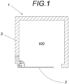
- the protective assembly intended to internally house a roller blind (not shown), suitable to be fixed to a wall or ceiling, generally comprises a covering box, generally indicated with the reference (1), and a hood, generally indicated with the reference (2), which can be linked with said covering box (1), which are described in greater detail below.
- the covering box (1) for roller elements suitable to be fixed to a wall or ceiling, and according to figures 1 , 2 and 3 , it comprises a casing (3) made up of an upper wall and multiple lateral walls such that they define an internal housing (100) intended to house the roller element, including the hood (2) located in the lower portion of the casing (3) provided with pivoting means to form an axis of rotation such that the hood (2) can pivot with respect to the casing (3) between a connected state (i.e., the hood (2) is coupled to the casing (3) in a closed position) and a disconnected state (i.e., the hood is tilted in a substantially vertical position with respect to the horizontal plane).
- a connected state i.e., the hood (2) is coupled to the casing (3) in a closed position
- a disconnected state i.e., the hood is tilted in a substantially vertical position with respect to the horizontal plane
- the pivoting means comprise a hollow (4) and a hook-shaped segment (5) intended to be coupled with a segment of the hood that has a complementary shape, which will be described later.
- the hollow (4) is defined by a vertical extension (30) that extends from a vertical lateral wall of the casing (3) and an elongated horizontal extension (31) from which the hook-shaped segment (5) extends vertically which defines a first point of rotation for a first segment of the hood and an upper curved segment (32) that is intended to make contact with a pressure force on a second segment of the hood (2) during the placement of the hood (2).
- an elongated segment (33) protrudes axially aligned with said elongated extension (31) that defines a second point of rotation for a third segment of the hood (2).
- the vertical extension (30) is offset with respect to the outermost face of the vertical lateral wall, defining a recess (6).
- the covering box (1) includes coupling means comprising a recessed portion (9) configured to be coupled with a segment of the hood that has a complementary shape, said recessed portion (9) being located above the hollow (4).
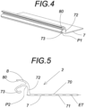
- the hood has a plate (7) with an internal side (70) oriented towards the housing defined by the covering box (1) and an external side (71) opposite to the internal side. Furthermore, pivoting means are provided which form a pivoting axis so that the hood is pivotable between a connected state and a disconnected state relative to the covering box (1).
- the pivoting means are arranged at one end of the plate (7) of the hood (2), having an extension (72) that ends with a hook-shaped segment (73) that acts as the first point of rotation (P1) with a segment of the covering box (1) and a second point of rotation (P2) present in the extension (72) that is linked to a second segment.
- the hood (2) also includes coupling means comprising a coupling branch (8) with a curved path and a certain flexural degree, which extends from the extension, configured to be coupled to the covering box (1) in a connected state, the end of the coupling branch having a substantially wedge-shaped widening (80) intended to be coupled to the recessed portion (9) in the connected state.
- coupling means comprising a coupling branch (8) with a curved path and a certain flexural degree, which extends from the extension, configured to be coupled to the covering box (1) in a connected state, the end of the coupling branch having a substantially wedge-shaped widening (80) intended to be coupled to the recessed portion (9) in the connected state.
- the angle ( ⁇ ) formed by a longitudinal axis (EC) of the horizontal elongated extension (31) of the covering box (1) and a longitudinal axis (ET) of the hood (2) is equal to or less than 90 degrees, such as can be appreciated in Figure 7 .
- the geometric configuration of both bodies provides stop means that prevent an angle greater than 90° between the longitudinal axis (EC) and the longitudinal axis (ET) when the hood (2) adopts a hanging arrangement. Consequently, the hood (2) is prevented from causing damage to the facings or glass of a glass window or door when it is in the disconnected state, i.e., hanging.
- Figure 8 shows the different movements that have to be carried out during the assembly of the hood (2).
- the operator To place the hood (2) in the casing (3) the operator must carry out a first vertical translation movement, and then a second translation movement in a horizontal plane. Subsequently, once a portion of the hood (2) is partially housed inside the casing (3), a rotation movement is carried out such that the respective aforementioned coupling means of the covering box and the protective hood are linked together to keep the hood (2) in a horizontal plane.
Landscapes
- Engineering & Computer Science (AREA)
- Structural Engineering (AREA)
- Architecture (AREA)
- Civil Engineering (AREA)
- Blinds (AREA)
- Closures For Containers (AREA)
Applications Claiming Priority (1)
| Application Number | Priority Date | Filing Date | Title |
|---|---|---|---|
| ES202132049U ES1283963Y (es) | 2021-10-20 | 2021-10-20 | Caja de cobertura y tapa para elementos enrollables |
Publications (3)
| Publication Number | Publication Date |
|---|---|
| EP4170121A1 true EP4170121A1 (fr) | 2023-04-26 |
| EP4170121C0 EP4170121C0 (fr) | 2025-04-30 |
| EP4170121B1 EP4170121B1 (fr) | 2025-04-30 |
Family
ID=78828529
Family Applications (1)
| Application Number | Title | Priority Date | Filing Date |
|---|---|---|---|
| EP22382954.0A Active EP4170121B1 (fr) | 2021-10-20 | 2022-10-10 | Boîte de recouvrement et capot pour éléments roulants |
Country Status (3)
| Country | Link |
|---|---|
| US (1) | US12448837B2 (fr) |
| EP (1) | EP4170121B1 (fr) |
| ES (2) | ES1283963Y (fr) |
Cited By (1)
| Publication number | Priority date | Publication date | Assignee | Title |
|---|---|---|---|---|
| FR3150545A1 (fr) * | 2023-06-29 | 2025-01-03 | Bhg | Pièce de maintien d’une trappe de visite de caisson de volet roulant |
Families Citing this family (1)
| Publication number | Priority date | Publication date | Assignee | Title |
|---|---|---|---|---|
| ES1283963Y (es) * | 2021-10-20 | 2022-03-09 | Bandalux Ind S A | Caja de cobertura y tapa para elementos enrollables |
Citations (3)
| Publication number | Priority date | Publication date | Assignee | Title |
|---|---|---|---|---|
| ES2526256A1 (es) | 2013-07-04 | 2015-01-08 | Luxe Perfil, S.L. | Cajón para puertas enrollables y persianas mejorado |
| DE202015003705U1 (de) * | 2015-05-21 | 2015-06-22 | Alukon Kg | Gehäusekasten |
| EP3628061A1 (fr) * | 2017-08-21 | 2020-04-01 | Blindspace AB | Élément de support allongé et couvercle destiné à être raccordé à l'élément de support |
Family Cites Families (6)
| Publication number | Priority date | Publication date | Assignee | Title |
|---|---|---|---|---|
| DE2262249C2 (de) * | 1972-12-20 | 1983-01-27 | Fa. Walter Paul, 7252 Weil der Stadt | Halteelement für einen Rolladenkasten |
| AT399200B (de) * | 1992-07-07 | 1995-03-27 | Scherz Josef Gmbh | Aufhängung für einen rollvorhang |
| US7441582B2 (en) * | 2004-09-17 | 2008-10-28 | Stephen Lukos | Anti-bow roller tube housing assembly |
| ITBO20040805A1 (it) * | 2004-12-23 | 2005-03-23 | Corradi S R L | Cassonetto per tendaggi avvolgibili. |
| GB2600162B (en) * | 2020-10-26 | 2023-04-26 | Blindspace Ab | A cover arrangement |
| ES1283963Y (es) * | 2021-10-20 | 2022-03-09 | Bandalux Ind S A | Caja de cobertura y tapa para elementos enrollables |
-
2021
- 2021-10-20 ES ES202132049U patent/ES1283963Y/es active Active
-
2022
- 2022-10-10 ES ES22382954T patent/ES3024996T3/es active Active
- 2022-10-10 EP EP22382954.0A patent/EP4170121B1/fr active Active
- 2022-10-17 US US18/047,262 patent/US12448837B2/en active Active
Patent Citations (3)
| Publication number | Priority date | Publication date | Assignee | Title |
|---|---|---|---|---|
| ES2526256A1 (es) | 2013-07-04 | 2015-01-08 | Luxe Perfil, S.L. | Cajón para puertas enrollables y persianas mejorado |
| DE202015003705U1 (de) * | 2015-05-21 | 2015-06-22 | Alukon Kg | Gehäusekasten |
| EP3628061A1 (fr) * | 2017-08-21 | 2020-04-01 | Blindspace AB | Élément de support allongé et couvercle destiné à être raccordé à l'élément de support |
Cited By (2)
| Publication number | Priority date | Publication date | Assignee | Title |
|---|---|---|---|---|
| FR3150545A1 (fr) * | 2023-06-29 | 2025-01-03 | Bhg | Pièce de maintien d’une trappe de visite de caisson de volet roulant |
| EP4488486A1 (fr) | 2023-06-29 | 2025-01-08 | Bhg | Pièce de maintien d'une trappe de visite de caisson de volet roulant |
Also Published As
| Publication number | Publication date |
|---|---|
| ES3024996T3 (en) | 2025-06-05 |
| EP4170121C0 (fr) | 2025-04-30 |
| ES1283963U (es) | 2021-12-16 |
| EP4170121B1 (fr) | 2025-04-30 |
| US20230118693A1 (en) | 2023-04-20 |
| ES1283963Y (es) | 2022-03-09 |
| US12448837B2 (en) | 2025-10-21 |
Similar Documents
| Publication | Publication Date | Title |
|---|---|---|
| EP4170121B1 (fr) | Boîte de recouvrement et capot pour éléments roulants | |
| CA2563971C (fr) | Dispositif de positionnement et lame de volet ameliores | |
| EP2839099B1 (fr) | Fermeture oscillante pour portes, fenêtres ou similaires | |
| KR102063732B1 (ko) | 미닫이창용 열림 보조장치 | |
| AU734601B2 (en) | Pivotable connection | |
| CN101936117B (zh) | 推拉平开门窗 | |
| EP4390030B1 (fr) | Fenêtre de toit avec un dispositif de levage et procédé d'assemblage d'un dispositif de levage | |
| KR101936371B1 (ko) | 틸트 앤 턴 도어가 설치된 폴딩 도어 | |
| BR112020007015A2 (pt) | relatório descritivo da patente de invenção para "dispositivo de fechamento para um compartimento elétrico, e compartimento elétrico correspondente | |
| EP3234294B1 (fr) | Lame de volet et volet roulant | |
| EP2109706B1 (fr) | Structure de support permettant de faire tourner des volets | |
| CA2836920C (fr) | Mecanisme d'actionnement de stores de type venitien | |
| JP5385645B2 (ja) | 上げ下げ窓 | |
| EP4006295B1 (fr) | Agencement de protection pour une fenêtre de toit, et fenêtre de toit comprenant un tel agencement de protection | |
| EP4041978B1 (fr) | Volet roulant à lames orientables doté d'un moyen simplifié de rotation angulaire | |
| IT202100017459A1 (it) | Porta scorrevole | |
| PL208642B1 (pl) | Kryta zawiasa drzwiowa lub okienna | |
| KR200340253Y1 (ko) | 개폐가 용이한 방범창 | |
| EP3623560B1 (fr) | Système de déplacement comprenant un système de verrouillage | |
| EP3299536B1 (fr) | Fenêtre de toit comprenant un ensemble de charnières ayant une séquence de mouvement améliorée | |
| KR102494469B1 (ko) | 손가락 끼임 방지 안전문 | |
| EP2924208B1 (fr) | Dispositif de verrouillage résistant aux effractions | |
| EP3290614A1 (fr) | Fenêtre de toit avec des propriétés d'isolation améliorées et comprenant un ensemble de charnières | |
| KR20150071855A (ko) | 방화문의 경첩장치 | |
| JPH0518458Y2 (fr) |
Legal Events
| Date | Code | Title | Description |
|---|---|---|---|
| PUAI | Public reference made under article 153(3) epc to a published international application that has entered the european phase |
Free format text: ORIGINAL CODE: 0009012 |
|
| STAA | Information on the status of an ep patent application or granted ep patent |
Free format text: STATUS: THE APPLICATION HAS BEEN PUBLISHED |
|
| AK | Designated contracting states |
Kind code of ref document: A1 Designated state(s): AL AT BE BG CH CY CZ DE DK EE ES FI FR GB GR HR HU IE IS IT LI LT LU LV MC ME MK MT NL NO PL PT RO RS SE SI SK SM TR |
|
| STAA | Information on the status of an ep patent application or granted ep patent |
Free format text: STATUS: REQUEST FOR EXAMINATION WAS MADE |
|
| 17P | Request for examination filed |
Effective date: 20230619 |
|
| RBV | Designated contracting states (corrected) |
Designated state(s): AL AT BE BG CH CY CZ DE DK EE ES FI FR GB GR HR HU IE IS IT LI LT LU LV MC ME MK MT NL NO PL PT RO RS SE SI SK SM TR |
|
| GRAP | Despatch of communication of intention to grant a patent |
Free format text: ORIGINAL CODE: EPIDOSNIGR1 |
|
| STAA | Information on the status of an ep patent application or granted ep patent |
Free format text: STATUS: GRANT OF PATENT IS INTENDED |
|
| GRAS | Grant fee paid |
Free format text: ORIGINAL CODE: EPIDOSNIGR3 |
|
| INTG | Intention to grant announced |
Effective date: 20250225 |
|
| GRAA | (expected) grant |
Free format text: ORIGINAL CODE: 0009210 |
|
| STAA | Information on the status of an ep patent application or granted ep patent |
Free format text: STATUS: THE PATENT HAS BEEN GRANTED |
|
| AK | Designated contracting states |
Kind code of ref document: B1 Designated state(s): AL AT BE BG CH CY CZ DE DK EE ES FI FR GB GR HR HU IE IS IT LI LT LU LV MC ME MK MT NL NO PL PT RO RS SE SI SK SM TR |
|
| REG | Reference to a national code |
Ref country code: CH Ref legal event code: EP Ref country code: GB Ref legal event code: FG4D |
|
| REG | Reference to a national code |
Ref country code: IE Ref legal event code: FG4D |
|
| REG | Reference to a national code |
Ref country code: DE Ref legal event code: R096 Ref document number: 602022013879 Country of ref document: DE |
|
| U01 | Request for unitary effect filed |
Effective date: 20250430 |
|
| REG | Reference to a national code |
Ref country code: ES Ref legal event code: FG2A Ref document number: 3024996 Country of ref document: ES Kind code of ref document: T3 Effective date: 20250605 |
|
| U07 | Unitary effect registered |
Designated state(s): AT BE BG DE DK EE FI FR IT LT LU LV MT NL PT RO SE SI Effective date: 20250508 |
|
| PG25 | Lapsed in a contracting state [announced via postgrant information from national office to epo] |
Ref country code: NO Free format text: LAPSE BECAUSE OF FAILURE TO SUBMIT A TRANSLATION OF THE DESCRIPTION OR TO PAY THE FEE WITHIN THE PRESCRIBED TIME-LIMIT Effective date: 20250730 Ref country code: GR Free format text: LAPSE BECAUSE OF FAILURE TO SUBMIT A TRANSLATION OF THE DESCRIPTION OR TO PAY THE FEE WITHIN THE PRESCRIBED TIME-LIMIT Effective date: 20250731 |
|
| PG25 | Lapsed in a contracting state [announced via postgrant information from national office to epo] |
Ref country code: PL Free format text: LAPSE BECAUSE OF FAILURE TO SUBMIT A TRANSLATION OF THE DESCRIPTION OR TO PAY THE FEE WITHIN THE PRESCRIBED TIME-LIMIT Effective date: 20250430 |
|
| PG25 | Lapsed in a contracting state [announced via postgrant information from national office to epo] |
Ref country code: HR Free format text: LAPSE BECAUSE OF FAILURE TO SUBMIT A TRANSLATION OF THE DESCRIPTION OR TO PAY THE FEE WITHIN THE PRESCRIBED TIME-LIMIT Effective date: 20250430 |
|
| PG25 | Lapsed in a contracting state [announced via postgrant information from national office to epo] |
Ref country code: RS Free format text: LAPSE BECAUSE OF FAILURE TO SUBMIT A TRANSLATION OF THE DESCRIPTION OR TO PAY THE FEE WITHIN THE PRESCRIBED TIME-LIMIT Effective date: 20250731 |
|
| PG25 | Lapsed in a contracting state [announced via postgrant information from national office to epo] |
Ref country code: IS Free format text: LAPSE BECAUSE OF FAILURE TO SUBMIT A TRANSLATION OF THE DESCRIPTION OR TO PAY THE FEE WITHIN THE PRESCRIBED TIME-LIMIT Effective date: 20250830 |
|
| U20 | Renewal fee for the european patent with unitary effect paid |
Year of fee payment: 4 Effective date: 20250922 |
|
| PG25 | Lapsed in a contracting state [announced via postgrant information from national office to epo] |
Ref country code: SM Free format text: LAPSE BECAUSE OF FAILURE TO SUBMIT A TRANSLATION OF THE DESCRIPTION OR TO PAY THE FEE WITHIN THE PRESCRIBED TIME-LIMIT Effective date: 20250430 |
|
| PG25 | Lapsed in a contracting state [announced via postgrant information from national office to epo] |
Ref country code: CZ Free format text: LAPSE BECAUSE OF FAILURE TO SUBMIT A TRANSLATION OF THE DESCRIPTION OR TO PAY THE FEE WITHIN THE PRESCRIBED TIME-LIMIT Effective date: 20250430 |
|
| PG25 | Lapsed in a contracting state [announced via postgrant information from national office to epo] |
Ref country code: SK Free format text: LAPSE BECAUSE OF FAILURE TO SUBMIT A TRANSLATION OF THE DESCRIPTION OR TO PAY THE FEE WITHIN THE PRESCRIBED TIME-LIMIT Effective date: 20250430 |
|
| PGFP | Annual fee paid to national office [announced via postgrant information from national office to epo] |
Ref country code: ES Payment date: 20251230 Year of fee payment: 4 |
|
| PLBE | No opposition filed within time limit |
Free format text: ORIGINAL CODE: 0009261 |
|
| STAA | Information on the status of an ep patent application or granted ep patent |
Free format text: STATUS: NO OPPOSITION FILED WITHIN TIME LIMIT |
|
| REG | Reference to a national code |
Ref country code: CH Ref legal event code: L10 Free format text: ST27 STATUS EVENT CODE: U-0-0-L10-L00 (AS PROVIDED BY THE NATIONAL OFFICE) Effective date: 20260311 |
|
| 26N | No opposition filed |
Effective date: 20260202 |