EP4170148A1 - Système et procédé d'atténuation d'arc de rotor de moteur à turbine à gaz - Google Patents
Système et procédé d'atténuation d'arc de rotor de moteur à turbine à gaz Download PDFInfo
- Publication number
- EP4170148A1 EP4170148A1 EP22201311.2A EP22201311A EP4170148A1 EP 4170148 A1 EP4170148 A1 EP 4170148A1 EP 22201311 A EP22201311 A EP 22201311A EP 4170148 A1 EP4170148 A1 EP 4170148A1
- Authority
- EP
- European Patent Office
- Prior art keywords
- gas turbine
- turbine engine
- rotor bow
- actuator
- gear
- Prior art date
- Legal status (The legal status is an assumption and is not a legal conclusion. Google has not performed a legal analysis and makes no representation as to the accuracy of the status listed.)
- Pending
Links
Images


Classifications
-
- F—MECHANICAL ENGINEERING; LIGHTING; HEATING; WEAPONS; BLASTING
- F02—COMBUSTION ENGINES; HOT-GAS OR COMBUSTION-PRODUCT ENGINE PLANTS
- F02C—GAS-TURBINE PLANTS; AIR INTAKES FOR JET-PROPULSION PLANTS; CONTROLLING FUEL SUPPLY IN AIR-BREATHING JET-PROPULSION PLANTS
- F02C7/00—Features, components parts, details or accessories, not provided for in, or of interest apart form groups F02C1/00 - F02C6/00; Air intakes for jet-propulsion plants
- F02C7/32—Arrangement, mounting, or driving, of auxiliaries
-
- F—MECHANICAL ENGINEERING; LIGHTING; HEATING; WEAPONS; BLASTING
- F02—COMBUSTION ENGINES; HOT-GAS OR COMBUSTION-PRODUCT ENGINE PLANTS
- F02C—GAS-TURBINE PLANTS; AIR INTAKES FOR JET-PROPULSION PLANTS; CONTROLLING FUEL SUPPLY IN AIR-BREATHING JET-PROPULSION PLANTS
- F02C7/00—Features, components parts, details or accessories, not provided for in, or of interest apart form groups F02C1/00 - F02C6/00; Air intakes for jet-propulsion plants
- F02C7/36—Power transmission arrangements between the different shafts of the gas turbine plant, or between the gas-turbine plant and the power user
-
- F—MECHANICAL ENGINEERING; LIGHTING; HEATING; WEAPONS; BLASTING
- F01—MACHINES OR ENGINES IN GENERAL; ENGINE PLANTS IN GENERAL; STEAM ENGINES
- F01D—NON-POSITIVE DISPLACEMENT MACHINES OR ENGINES, e.g. STEAM TURBINES
- F01D25/00—Component parts, details, or accessories, not provided for in, or of interest apart from, other groups
- F01D25/34—Turning or inching gear
- F01D25/36—Turning or inching gear using electric motors
-
- F—MECHANICAL ENGINEERING; LIGHTING; HEATING; WEAPONS; BLASTING
- F02—COMBUSTION ENGINES; HOT-GAS OR COMBUSTION-PRODUCT ENGINE PLANTS
- F02C—GAS-TURBINE PLANTS; AIR INTAKES FOR JET-PROPULSION PLANTS; CONTROLLING FUEL SUPPLY IN AIR-BREATHING JET-PROPULSION PLANTS
- F02C9/00—Controlling gas-turbine plants; Controlling fuel supply in air- breathing jet-propulsion plants
- F02C9/16—Control of working fluid flow
- F02C9/18—Control of working fluid flow by bleeding, bypassing or acting on variable working fluid interconnections between turbines or compressors or their stages
-
- F—MECHANICAL ENGINEERING; LIGHTING; HEATING; WEAPONS; BLASTING
- F05—INDEXING SCHEMES RELATING TO ENGINES OR PUMPS IN VARIOUS SUBCLASSES OF CLASSES F01-F04
- F05D—INDEXING SCHEME FOR ASPECTS RELATING TO NON-POSITIVE-DISPLACEMENT MACHINES OR ENGINES, GAS-TURBINES OR JET-PROPULSION PLANTS
- F05D2220/00—Application
- F05D2220/30—Application in turbines
- F05D2220/32—Application in turbines in gas turbines
- F05D2220/323—Application in turbines in gas turbines for aircraft propulsion, e.g. jet engines
-
- F—MECHANICAL ENGINEERING; LIGHTING; HEATING; WEAPONS; BLASTING
- F05—INDEXING SCHEMES RELATING TO ENGINES OR PUMPS IN VARIOUS SUBCLASSES OF CLASSES F01-F04
- F05D—INDEXING SCHEME FOR ASPECTS RELATING TO NON-POSITIVE-DISPLACEMENT MACHINES OR ENGINES, GAS-TURBINES OR JET-PROPULSION PLANTS
- F05D2260/00—Function
- F05D2260/40—Transmission of power
- F05D2260/403—Transmission of power through the shape of the drive components
- F05D2260/4031—Transmission of power through the shape of the drive components as in toothed gearing
-
- F—MECHANICAL ENGINEERING; LIGHTING; HEATING; WEAPONS; BLASTING
- F05—INDEXING SCHEMES RELATING TO ENGINES OR PUMPS IN VARIOUS SUBCLASSES OF CLASSES F01-F04
- F05D—INDEXING SCHEME FOR ASPECTS RELATING TO NON-POSITIVE-DISPLACEMENT MACHINES OR ENGINES, GAS-TURBINES OR JET-PROPULSION PLANTS
- F05D2260/00—Function
- F05D2260/94—Functionality given by mechanical stress related aspects such as low cycle fatigue [LCF] of high cycle fatigue [HCF]
- F05D2260/941—Functionality given by mechanical stress related aspects such as low cycle fatigue [LCF] of high cycle fatigue [HCF] particularly aimed at mechanical or thermal stress reduction
Definitions
- a gas turbine engine that includes a towershaft mechanically connected to the rotary component and the external gearbox; and a rotor bow mitigation system in selective mechanical connection with the external gearbox, wherein the rotor bow mitigation system is configured to repeatedly actuate an actuator to intermittently rotate the rotary component of the gas turbine engine to mitigate rotor bow conditions.
- the actuator is a linear actuator.
- intermittently actuating the linear actuator utilizes bleed air from the gas turbine engine collected in an accumulator which is then released intermittently.
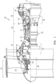
- Gas turbine engines may have a range of different shaft and spool geometries, including one-spool, two-spool and three-spool configurations, in both corotating and counter-rotating designs. Gas turbine engines may also be configured as low bypass turbofan, open-rotor turbofan, ducted or un-ducted propeller engines, turboshaft configurations or as an industrial gas turbine. It should be appreciated that the rotor bow mitigation disclosed herein can be beneficially utilized to mitigate rotor bow in any rotary component such as a spool or rotor or the like in any of these and other gas turbine engines.
- the external gearbox 60 supports accessory components (ACs) such as, for example, an air turbine starter, a de-oiler, a hydraulic pump, an engine lubrication pump, an integrated drive generator, a permanent magnet alternator, a fuel pump module, and others.
- ACs accessory components
- Each accessory component typically has an input shaft that defines an axis of rotation C parallel or at least generally parallel to axis L. It should be appreciated that any number and type of accessory components AC may alternatively or additionally be provided.
- the external gearbox 60 allows each accessory component AC to be driven at an optimum speed and in an accessible location for ease of maintenance, reduced weight and minimum complexity.
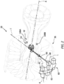
- the towershaft 66 may include a towershaft bevel gear 70 that drives an accessory gear train 72 contained and supported within an accessory drive gearbox casing 62.
- the accessory gear train 72 in one embodiment, includes a polygonal transmission with associated gears 74 and supporting bearings to provide the required accessory component input speed and power.
- the gears 74 may be arranged along respective axes C that are transverse to the axis T of the towershaft 66 and parallel to the engine longitudinal axis A.
- the towershaft bevel gear 70 may interface with a spiral bevel gear 80 that then drives the accessory gear train 72.
- a rotor bow mitigation system 100 in one embodiment may be mechanically coupled to the external gearbox 60. Operation of the rotor bow mitigation system 100, in one embodiment, drives the gear 80 which, in turn, drives the towershaft 66 thence the high spool 32. As discussed below, this can be done to periodically or intermittently turn the high spool 32 during cooling to mitigate rotor bow conditions. Although illustrated as driving the spiral bevel gear, the rotor bow mitigation system 100 may alternatively drive any of the gears in the accessory gear train 72.
- the linear actuator 104 provides axial motion along an axis L.
- the linear actuator 104 may be operated by the power source 106 which may provide power mechanically, electromechanically, piezo-electrically, pneumatically, hydraulically, and/or combinations thereof.
- bleed air from the gas turbine engine 20 may be collected in an accumulator which operates as the power source 106, and can then be released intermittently as controlled by the logic 112.
- the linear actuator 104 may include an actuator 130 such as a hydraulic cylinder, a rack and pinion system, a ball screw, or any type of device capable of providing controlled axial motion to actuate a piston 132 along the axis L.
- the linear actuator 104 may be readily installed within or on the accessory drive gearbox casing 62 to facilitate maintenance thereof.
- algorithms in the control system 102 identify a potential rotor bow condition from data provided by, for example, one or more sensor inputs (202).
- the potential rotor bow condition may be determined by, for example, an aircraft sensor, a temperature of a static component, the differential temperature between the sensors 108A, 108B, a time from shut-down, an idle operation time of the engine prior to the previous shutdown, a pressure within the power source 106, etc. Because the magnitude of rotor distortion exhibits a predictable profile as a function of time, the rotor bow mitigation cycle can be prescribed. Also, the more time spent by the engine at a low power setting (e.g. while taxiing or idling) prior to shut-down, the less time is required to alleviate rotor distortion (i.e. the lower the duration of the prescribed rotor bow mitigation cycle).
- the linear actuator 104 may be preprogrammed or triggered by the FADEC to operate autonomously according to a FADEC defined period and duration (e.g., one actuation every X seconds for Y minutes).
- the period and duration may be defined by the FADEC after engine shutdown and sent to the control system 102 such that the FADEC may thereafter be depowered.
Landscapes
- Engineering & Computer Science (AREA)
- Chemical & Material Sciences (AREA)
- Combustion & Propulsion (AREA)
- Mechanical Engineering (AREA)
- General Engineering & Computer Science (AREA)
- Physics & Mathematics (AREA)
- Fluid Mechanics (AREA)
- Control Of Turbines (AREA)
- Retarders (AREA)
Applications Claiming Priority (1)
| Application Number | Priority Date | Filing Date | Title |
|---|---|---|---|
| US17/506,986 US20230129383A1 (en) | 2021-10-21 | 2021-10-21 | System and method for gas turbine engine rotor bow mitigation |
Publications (1)
| Publication Number | Publication Date |
|---|---|
| EP4170148A1 true EP4170148A1 (fr) | 2023-04-26 |
Family
ID=83692883
Family Applications (1)
| Application Number | Title | Priority Date | Filing Date |
|---|---|---|---|
| EP22201311.2A Pending EP4170148A1 (fr) | 2021-10-21 | 2022-10-13 | Système et procédé d'atténuation d'arc de rotor de moteur à turbine à gaz |
Country Status (2)
| Country | Link |
|---|---|
| US (1) | US20230129383A1 (fr) |
| EP (1) | EP4170148A1 (fr) |
Families Citing this family (1)
| Publication number | Priority date | Publication date | Assignee | Title |
|---|---|---|---|---|
| US12078105B2 (en) * | 2022-06-14 | 2024-09-03 | General Electric Company | System and method for providing cooling in a compressor section of a gas turbine engine |
Citations (8)
| Publication number | Priority date | Publication date | Assignee | Title |
|---|---|---|---|---|
| US3684039A (en) * | 1970-09-21 | 1972-08-15 | Ingersoll Rand Co | Drill rod indexing device |
| US4018094A (en) * | 1974-09-11 | 1977-04-19 | Sulzer Turbomaschinen Ag | Apparatus for intermittently turning a turbine shaft |
| JPH062570A (ja) * | 1992-06-19 | 1994-01-11 | Mitsubishi Heavy Ind Ltd | ガスタービン |
| EP2757230A1 (fr) * | 2013-01-16 | 2014-07-23 | Alstom Technology Ltd | Procédé pour la rotation d'un rotor de turbomachine et appareil de rotation pour appliquer ce procédé |
| US20140318144A1 (en) * | 2011-11-14 | 2014-10-30 | Nuovo Pignone S.P.A. | Device and method for slow turning of an aeroderivative gas turbine |
| US20170234230A1 (en) * | 2016-02-12 | 2017-08-17 | United Technologies Corporation | Bowed rotor start using direct temperature measurement |
| EP3382182A1 (fr) * | 2017-03-29 | 2018-10-03 | Hamilton Sundstrand Corporation | Ensemble d'entraînement pour moteur de turbine à gaz |
| US20190186359A1 (en) * | 2017-12-15 | 2019-06-20 | Rolls-Royce Plc | Rotor bow management |
Family Cites Families (6)
| Publication number | Priority date | Publication date | Assignee | Title |
|---|---|---|---|---|
| US4919039A (en) * | 1988-07-25 | 1990-04-24 | General Electric Company | Hydraulic turning gear |
| US5178028A (en) * | 1990-09-27 | 1993-01-12 | Lucas Western, Inc. | Offset face gear transmission |
| FR2985285A1 (fr) * | 2011-12-29 | 2013-07-05 | Alstom Technology Ltd | Dispositif d'actionnement en rotation d'une ligne d'arbre de turbine. |
| US9664070B1 (en) * | 2016-02-12 | 2017-05-30 | United Technologies Corporation | Bowed rotor prevention system |
| US10495003B1 (en) * | 2016-07-05 | 2019-12-03 | Hamilton Sunstrand Corporation | Gas turbine engine starter reduction gear train with jacking and planetary geared transmission |
| US10479525B2 (en) * | 2018-04-03 | 2019-11-19 | Kidde Technologies, Inc. | Utilization of engine bleed air to provide extended duration emergency aircraft power |
-
2021
- 2021-10-21 US US17/506,986 patent/US20230129383A1/en active Pending
-
2022
- 2022-10-13 EP EP22201311.2A patent/EP4170148A1/fr active Pending
Patent Citations (8)
| Publication number | Priority date | Publication date | Assignee | Title |
|---|---|---|---|---|
| US3684039A (en) * | 1970-09-21 | 1972-08-15 | Ingersoll Rand Co | Drill rod indexing device |
| US4018094A (en) * | 1974-09-11 | 1977-04-19 | Sulzer Turbomaschinen Ag | Apparatus for intermittently turning a turbine shaft |
| JPH062570A (ja) * | 1992-06-19 | 1994-01-11 | Mitsubishi Heavy Ind Ltd | ガスタービン |
| US20140318144A1 (en) * | 2011-11-14 | 2014-10-30 | Nuovo Pignone S.P.A. | Device and method for slow turning of an aeroderivative gas turbine |
| EP2757230A1 (fr) * | 2013-01-16 | 2014-07-23 | Alstom Technology Ltd | Procédé pour la rotation d'un rotor de turbomachine et appareil de rotation pour appliquer ce procédé |
| US20170234230A1 (en) * | 2016-02-12 | 2017-08-17 | United Technologies Corporation | Bowed rotor start using direct temperature measurement |
| EP3382182A1 (fr) * | 2017-03-29 | 2018-10-03 | Hamilton Sundstrand Corporation | Ensemble d'entraînement pour moteur de turbine à gaz |
| US20190186359A1 (en) * | 2017-12-15 | 2019-06-20 | Rolls-Royce Plc | Rotor bow management |
Also Published As
| Publication number | Publication date |
|---|---|
| US20230129383A1 (en) | 2023-04-27 |
Similar Documents
| Publication | Publication Date | Title |
|---|---|---|
| EP3628820B1 (fr) | Refroidissement de système de moteur à turbine à gaz | |
| EP3514335B1 (fr) | Systèmes et procédés d'extraction d'énergie de corps basse vitesse | |
| EP2584171B1 (fr) | Système d'entraînement d'accessoires divisé | |
| US10267233B2 (en) | Method and apparatus for monitoring lubrication pump operation during windmilling | |
| EP2898205B1 (fr) | Boîte d'engrenages d'accessoire de moteur à turbine à gaz à réducteur | |
| EP3205841A1 (fr) | Système de prévention de déformation de rotor au moyen de la chaleur perdue et le procédé correspondant | |
| EP3498988B1 (fr) | Gestion de courbure de rotor dans un rotor haute pression d'un moteur à turbine à gaz | |
| US10760498B2 (en) | System and method for removing rotor bow in a gas turbine engine using mechanical energy storage device | |
| US12123344B2 (en) | Engine and secondary power unit integrated operation | |
| EP3399157B1 (fr) | Rotation d'un moteur de turbine par l'intermédiaire d'un moteur pneumatique ou hydraulique | |
| EP2961970B1 (fr) | Arrangement de turbine à gaz et procédé de contrôle de la rotation de la soufflante | |
| US9879558B2 (en) | Low leakage multi-directional interface for a gas turbine engine | |
| US9797268B2 (en) | Oil scoop with integrated sensor | |
| WO2014197074A2 (fr) | Joint de type curvic pour moteur à turbine à gaz | |
| US20190292993A1 (en) | Electric propulsion motor cooling system and method | |
| CA3112117A1 (fr) | Systeme de demarrage et methode d`attenuation de la deformation du rotor | |
| US20230129383A1 (en) | System and method for gas turbine engine rotor bow mitigation | |
| US20140255167A1 (en) | Consumable assembly tool for a gas turbine engine | |
| GB2616901A (en) | System and method for use with gas turbine engine | |
| EP3470630A1 (fr) | Tube de service à double paroi avec un passage d'écoulement d'air annulaire | |
| US10294823B2 (en) | Dirt evacuation devices | |
| US11236672B2 (en) | Oil thermal management system for cold weather operations of a gas turbine engine | |
| US12209540B2 (en) | Bowed-rotor mitigation system for a gas turbine | |
| EP2009451A2 (fr) | Générateur de signal synchrone pour équilibrage d'un réacteur | |
| EP2917630B1 (fr) | Système de lubrification à réserve sous pression pour moteur à turbine à gaz |
Legal Events
| Date | Code | Title | Description |
|---|---|---|---|
| PUAI | Public reference made under article 153(3) epc to a published international application that has entered the european phase |
Free format text: ORIGINAL CODE: 0009012 |
|
| STAA | Information on the status of an ep patent application or granted ep patent |
Free format text: STATUS: THE APPLICATION HAS BEEN PUBLISHED |
|
| AK | Designated contracting states |
Kind code of ref document: A1 Designated state(s): AL AT BE BG CH CY CZ DE DK EE ES FI FR GB GR HR HU IE IS IT LI LT LU LV MC ME MK MT NL NO PL PT RO RS SE SI SK SM TR |
|
| STAA | Information on the status of an ep patent application or granted ep patent |
Free format text: STATUS: REQUEST FOR EXAMINATION WAS MADE |
|
| RAP3 | Party data changed (applicant data changed or rights of an application transferred) |
Owner name: RTX CORPORATION |
|
| 17P | Request for examination filed |
Effective date: 20231026 |
|
| RBV | Designated contracting states (corrected) |
Designated state(s): AL AT BE BG CH CY CZ DE DK EE ES FI FR GB GR HR HU IE IS IT LI LT LU LV MC ME MK MT NL NO PL PT RO RS SE SI SK SM TR |
|
| STAA | Information on the status of an ep patent application or granted ep patent |
Free format text: STATUS: EXAMINATION IS IN PROGRESS |
|
| 17Q | First examination report despatched |
Effective date: 20250319 |