EP4170217B1 - Leitungskupplung, leitungskupplungsglied und leitung - Google Patents
Leitungskupplung, leitungskupplungsglied und leitung Download PDFInfo
- Publication number
- EP4170217B1 EP4170217B1 EP22199589.7A EP22199589A EP4170217B1 EP 4170217 B1 EP4170217 B1 EP 4170217B1 EP 22199589 A EP22199589 A EP 22199589A EP 4170217 B1 EP4170217 B1 EP 4170217B1
- Authority
- EP
- European Patent Office
- Prior art keywords
- conduit
- conduit coupling
- receiving collar
- coupling member
- coupling
- Prior art date
- Legal status (The legal status is an assumption and is not a legal conclusion. Google has not performed a legal analysis and makes no representation as to the accuracy of the status listed.)
- Active
Links
Images


Classifications
-
- F—MECHANICAL ENGINEERING; LIGHTING; HEATING; WEAPONS; BLASTING
- F16—ENGINEERING ELEMENTS AND UNITS; GENERAL MEASURES FOR PRODUCING AND MAINTAINING EFFECTIVE FUNCTIONING OF MACHINES OR INSTALLATIONS; THERMAL INSULATION IN GENERAL
- F16L—PIPES; JOINTS OR FITTINGS FOR PIPES; SUPPORTS FOR PIPES, CABLES OR PROTECTIVE TUBING; MEANS FOR THERMAL INSULATION IN GENERAL
- F16L37/00—Couplings of the quick-acting type
- F16L37/08—Couplings of the quick-acting type in which the connection between abutting or axially overlapping ends is maintained by locking members
- F16L37/12—Couplings of the quick-acting type in which the connection between abutting or axially overlapping ends is maintained by locking members using hooks, pawls, or other movable or insertable locking members
- F16L37/20—Joints tightened by toggle-action levers
Definitions
- the invention relates to a conduit coupling for coupling two conduit sections to each other, a conduit coupling member for use in the conduit coupling, and a conduit comprising the conduit coupling or the conduit coupling member.
- a known conduit coupling comprises a first conduit coupling member having a circumferential receiving collar, a second conduit coupling member having a coupling section facing the first coupling end, and a securing or clamping arrangement.
- the clamping arrangement comprises two securing members or claws that are pivotably connected to the first conduit coupling member at opposite sides thereof, and a circumferential clamping ridge at the outer surface of coupling section of the second conduit coupling member. The claws can hook behind and engage with the clamping ridge to secure the first coupling end and the second coupling end together, to thereby couple the two conduit sections.
- a conduit coupling according to the preamble of independent claim 1 is known from DE 82 29 357 U1 .
- a disadvantage of the known conduit coupling is that during use, handling and transportation it can get easily damaged, for instance when the conduit coupling or parts thereof are dropped on a floor surface.
- the damaged conduit coupling may cause ill fitment between the receiving collar of the first conduit coupling member and the coupling section of the second conduit coupling member, as the dimensions of the damaged conduit coupling may fall outside the fitting tolerances thereof.
- the ill fitment can for instance cause a leaking or non-watertight coupling between the conduit sections.
- the ill fitment can also make it harder, or even impossible, to fit the receiving collar and the coupling section together
- the invention provides a conduit coupling for coupling a first conduit section and a second conduit section, wherein the conduit coupling comprises a first conduit coupling member configured for being arranged on the first conduit section, and a securing arrangement for securing the first conduit coupling member to a second conduit coupling member on the second conduit section, wherein the first conduit coupling member comprises a first coupling tube with a longitudinal center axis, and that merges into a circumferential receiving collar for receiving a distal end of the second conduit coupling member, and a circumferential distal edge that defines a receiving opening towards the receiving collar, wherein the securing arrangement comprises two claws that are provided outside the first coupling tube at opposite sides of the longitudinal center axis, wherein the respective claws extend over the receiving collar and beyond the distal edge, wherein the first conduit coupling member comprises at least one guard block on the receiving collar to reinforce the receiving collar, wherein the at least one guard block outwardly protrudes with respect to the receiving collar, and is provided in
- the conduit coupling establishes the securing of the first conduit coupling member to the second conduit coupling member by clamping the receiving collar and the coupling section together.
- the inventers When investigating the flawed connection of the conduit coupling, the inventers surprisingly found that in a majority of cases the receiving collar is the cause of the flawed connection as it was damaged to such an extent that it fell outside the tolerance.
- the inventors presume that this is because the first conduit coupling member comprises the claws of the securing arrangement and is therefore heavier than the second conduit coupling member. Due to the higher weight of the first conduit coupling member, when it gets dropped on the floor surface, the impact on the receiving collar is higher as compared to the impact on the coupling section of the second conduit coupling member. As a result the damage caused by a fall to the receiving collar is more severe as compared to the damage caused by a fall to the coupling section.
- the inventors When further investigating the damaged receiving collars of the first conduit coupling member the inventors surprisingly found that two areas of the receiving collar got most frequently damaged. These areas lie for the most part, in a circumferential direction, between the securing members at respective opposite sides of the receiving collar with respect to the longitudinal center axis.
- the inventors presume that the claws that are provided at the outer surface of the tube at opposite sides thereof, and that extend over the receiving collar and beyond the distal edge, protect or guard the receiving collar, when it gets dropped on the floor surface, at the area near the claws.
- the guard block merges into or is provided adjacent to or near the distal edge.
- the guard block specifically provides added stiffness and increased resistance against damage to the distal edge of the receiving collar. As the distal edge is the most fragile part of the receiving collar this further reduces the risk of the conduit coupling getting damaged.
- the guard block protrudes outwardly from the receiving collar beyond the circumferential apex. As the convex receiving collar protrudes from the first coupling member, the receiving collar will more likely get damaged at or near the apex thereof. When the guard block protrudes beyond the apex, the guard block provides increased resistance against damage of the receiving collar near the apex, especially when the receiving collar drops on the floor surface near these areas.
- the guard block comprises a support surface facing away from the receiving collar.
- the support surface extends parallel to the longitudinal center axis.
- the conduit coupling and/or the conduit coupling member can be placed with the support surface on a surface, for instance the floor surface.
- the support surface provides a stable base so that the conduit coupling and/or the conduit coupling member is less likely to tumble over, to get dropped and as a result to get damaged.
- the guard block has a rectangular outline. In an embodiment the guard block extends along 2-10% of the circumference of the receiving collar, preferably along 50 of the circumference of the receiving collar.
- the guard blocks extend in the longitudinal direction thereof along the circumference of the first coupling end. The longitudinal length of the rectangular guard blocks can be adjusted according to the size of the area of the coupling end that gets most frequently damaged.
- the first conduit coupling member comprises two guard blocks that are provided at opposite sides of the longitudinal center axis.
- both guard blocks comprise a support surface, and the respective support surfaces extend parallel to each other.
- the two guard blocks are identical to each other.
- the conduit coupling comprises the second conduit coupling member, wherein the second conduit coupling member comprises a second coupling tube that has a coupling section facing the receiving collar, and a circumferential engagement ridge that protrudes outwardly from the outer surface of the second coupling tube, and wherein the claws are configured for engaging the engagement ridge for securing the first conduit coupling member to the second conduit coupling member.
- the invention provides a conduit coupling member for use in the conduit coupling according to any one of the aforementioned embodiments, wherein the conduit coupling member comprises a coupling tube with a longitudinal center axis, and that merges into a circumferential receiving collar, and a circumferential distal edge that defines a receiving opening towards the receiving collar, wherein the conduit coupling member comprises at least one guard block on the receiving collar to reinforce the receiving collar, wherein the at least one guard block outwardly protrudes with respect to the receiving collar, wherein the receiving collar is convex in a direction away from the longitudinal center axis, and has a circumferential apex at a distance from the distal edge, wherein the guard block is provided between the apex and the distal edge, and wherein the guard block has a rectangular outline.
- the invention provides a conduit comprising the conduit coupling or the conduit coupling member according to any one of the aforementioned embodiments.
- conduit coupling member and the conduit relate to the conduit coupling according to any one of the aforementioned embodiments and thus have at least the same technical advantages, which will not be repeated hereafter.
- DE 82 29 357 U1 discloses a tube coupling having an inlet and two hooks on a ringshaped bracket.
- the bracket is supported by two bearings that are formed behind the inlet. These bearings do not protect or guard the projecting outlet.
- US 2006/131876 A1 discloses a coupler having two hooks at a clamping sleeve.
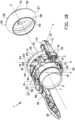
- Figures 1A and 1B show a conduit coupling 1 for coupling a first conduit section 2 to a second conduit section 3.
- the conduit coupling 1 comprises a first conduit coupling member 10 that is connected, connectable to or merges into the first conduit section 2, and a second conduit coupling member 50 that is connected, connectable to or merges into the second conduit section 3.
- the conduit coupling 1 comprises a securing arrangement or clamping arrangement 30 in order to couple the first conduit section 2 to the second conduit section 3.
- the conduit sections 2, 3 can be a hose, tube or pipe and may be part of or integrated with an adapter piece or equipment such as a pump, a turbine or a valve, or couplings such as bends, T-pieces, Y-pieces or reducers.
- the first conduit coupling member 10 comprises a first coupling tube 11 with a center axis that coincides with a longitudinal center axis Z of the conduit coupling 1.
- a circumferential ridge 14 is formed that divides the first coupling tube 11 in a first connecting section 15 and a first coupling section 16.
- the first connecting section 15 and most part of the first coupling section 16 of the first coupling tube 11 has a substantially constant diameter.
- the first coupling section 16 comprises or merges into a circumferential receiving collar 17 for receiving a distal end of the second conduit coupling member 50.
- the receiving collar 17 terminates in a circumferential distal edge 13 that is located in a notional first plane XY that is substantially transverse to the center axis Z. In this example the distal edge forms a distal end face in the notional first plane XY.
- the receiving collar 17 is generally convex outwards and has a proximal section 18 that is curved and flared away from the center axis Z.
- the proximal section 18 merges, via a circumferential first apex 20 into a distal section 19 that is curved back towards the center axis Z.
- the receiving collar 17 defines a circumferential gasket seat 21 that encloses a ring shaped gasket 22 that has, in its normal state, a circular cross section.
- the first coupling tube 11 comprises multiple reinforcing ribs 25 that extend at the proximal section 18 of the receiving collar 17, substantially parallel to the center axis Z.
- the second conduit coupling member 50 comprises a second coupling tube 51 having a center axis that, in a coupled state of the conduit coupling 1, coincides with the longitudinal center axis Z of the conduit coupling 1.
- the second coupling tube 51 comprises a second connecting section 54 that merges into an opposite second coupling section 53.
- the second connecting section 54 is substantially straight and extends parallel to the center axis Z.
- the second coupling section 53 comprises an engaging or clamping section 55 that, from the second connecting section 54, curves away from the center axis Z over more than 90 degrees so that the clamping section 55 extends outwardly from the second connecting section 54 obliquely away from the center axis Z.
- the clamping section 55 further curves back in the opposite direction to a circumferential second apex 56. At the second apex 56 the clamping section 55 merges into an abutment section 57 that curves back towards the center axis Z.
- the clamping section 55 defines a circumferential engagement ridge or clamping ridge 60 at the outer surface of the second coupling section 53 of the second coupling tube 51.
- the clamping section 55 defines a circumferential concave clamping gutter 61 at the outer surface of the second coupling section 53.
- the abutment section 57 defines a circumferential convex outer abutment surface 58 that corresponds to the first coupling section 16 of the first conduit coupling member 10, more particular that corresponds to the gasket 22 thereof.
- the clamping arrangement 30 comprises a ring 31 that surrounds the first coupling section 16 of the first coupling tube 11 and that is pivotably connected to the first coupling tube 11.
- the ring 31 is composed of two substantially identical semicircular ring sections 33 that are connected to or connectable to each other at their respective ends to form the ring 31.
- Each ring section 33 is pivotably connected to the first coupling tube 11 by a pivot 32.
- Each pivot 32 in this example, is composed of a socket on the outer surface of the first coupling section 16, and a corresponding cam on the inner surface of the ring section 33 that is received in the socket.
- the pivots 32 are arranged at two opposite sides of the first coupling tube 11 with respect to the longitudinal center axis Z, such that the ring 31 is pivotable with respect to the first coupling tube 11 around a ring pivot axis P in a ring pivot direction N.
- the ring pivot axis P is substantially transverse to and intersects the center axis Z.
- the clamping arrangement 30 comprises a first securing member or first claw 70 that is provided outside the first coupling tube 11.
- the first claw 70 is pivotably connected to one of the ring sections 33 of the ring 31, such that the first claw 70 is pivotable with respect to the ring 31, and therefore with respect to the first coupling tube 11, around a first claw pivot axis C in a first claw pivot direction K.
- the first claw pivot axis C is substantially parallel to the ring pivot axis P.
- the first claw 70 comprises a substantially elongate first claw body 71 that at a first base end 72 is pivotably connected to the ring 31, and that at the opposite end merges into a first hook portion 73 that is configured to hook behind the clamping ridge 60 and/or to hook into the clamping gutter 61 for securing the first conduit coupling member 10 to the second conduit coupling member 50.
- the clamping arrangement 30 comprises a second securing member or second claw 36 that is provided outside the first coupling tube 11.
- the second claw 36 is pivotably connected to the lever 35, such that the second claw 36 is pivotable with respect to the lever 35, and therefore with respect to the ring 31 and the first coupling tube 11, around a second claw pivot axis F in a second claw pivot direction M.
- the second claw pivot axis F is substantially parallel to the ring pivot axis P, to the first claw pivot axis C, and to the lever pivot axis E.
- the second claw pivot axis F is spaced apart from the lever pivot axis E.
- the second claw 36 comprises a substantially elongate second claw body 37 that at a second base end 38 is pivotably connected to the ring 31, and that at the opposite end merges into a second hook portion 39 that is configured to hook behind the clamping ridge 60 and/or to hook into the clamping gutter 61.
- the first conduit coupling member 10 and the second coupling member 50 can be secured or clamped to each other in a way that is known per se. Firstly the abutment section 57 is received in the receiving collar 17, with the outer abutment surface 58 abutted against the gasket 22. Secondly the first claw 70 and the second claw 36 are engaged with the engaging section 55. Lastly the lever 35 is pivoted towards the first coupling tube 11 to therewith clamp the outer abutment surface 58 tightly against the gasket 22 to form a watertight connection.
- first conduit section 2 is connected to the first conduit coupling member 10 by sliding it around the first connecting section 15 up to the ridge 14.
- the first conduit section 2 can be further secured to the first conduit coupling member 10 by gluing it to the first connecting section 15, by clamping it around the first connecting section 15, for instance using a hose clamp, or by welding.
- the second conduit section 3 can be coupled to the second conduit coupling member 50 in a similar fashion.
- the first conduit coupling member 10 comprises, in this example, two guard blocks 23 on the receiving collar 17.
- the guard blocks 23 are provided at and merge at their base into the receiving collar 17 near or adjacent to the distal edge 13 of the receiving collar 17.
- the guard blocks 23 protrude outwardly with respect to the receiving collar 17, away from the center axis Z substantially parallel to and in or adjacent to the notional first plane XY of the distal edge 13.
- the respective guard blocks 23 are provided at two opposite sides of the first coupling tube 11 with respect to the center axis Z.
- the respective guard blocks 23 are provided, in a circumferential direction of the receiving collar 17, between the first claw 70 and the second claw 36.
- the two guard blocks 23 are in particular arranged between the circumferential first apex 20 and the distal edge 13.
- Each guard block 23 extends along 2-10% of the circumference of the receiving collar 17, preferably each guard block 23 extends along approximately 5% of the circumference of the receiving collar 17.
- the guard blocks 23 reinforce the receiving collar 17, at least at or near the location of the guard blocks 23.
- the guard blocks 23 have a rectangular shaped outline.
- the guard blocks 23 comprise a straight or plane rectangular support surface 24 that faces away from the collar, that is parallel to the longitudinal center axis Z, and that extends along a part of the circumference of the receiving collar 17.
- the first claw 70 and the second claw 36 are provided at opposite sides of the first coupling tube 11 with respect to the center axis Z, and lie in a common notional second plane YZ that is parallel to and coincides with the center axis Z and that is transverse to the first plane XY.
- the first claw 70 and the second claw 36 extend over the first apex 20 of the receiving collar 17, through the notional first plane XY, and beyond the distal edge 13.
- the guard blocks 23 lie in a common notional third plane XZ that is parallel to and coincides with the longitudinal center axis Z and that is transverse to the first plane XY and to the second plane YZ.
- the notional second plane YZ and the notional third plane XZ intersect along the center axis Z.
- the respective pivots 32 are aligned with the respective guard blocks 23 in the notional third plane XZ.
- Figure 2 is a transverse view of the first conduit coupling member 10 showing the distal edge 13 thereof.
- lines T notional straight support planes, such as a floor surface, that are parallel to the center axis Z are indicated.
- the lines T extend between respective extremities of the first claw 70, the second claw 36 and the guard blocks 23.
- the lines T do not intersect the distal edge 13.
- the guard blocks 23 in cooperation with the first claw 70 and the second claw 36 protect the distal edge 13, which is the most fragile part of the conduit coupling 1, when the first conduit coupling member 10 is resting on the floor.
- the guard blocks 23, the first claw 70 and the second claw 36 are arranged such that together they protect the distal edge 13.
Landscapes
- Engineering & Computer Science (AREA)
- General Engineering & Computer Science (AREA)
- Mechanical Engineering (AREA)
- Quick-Acting Or Multi-Walled Pipe Joints (AREA)
Claims (13)
- Leitungskupplung (1) zum Koppeln eines ersten Leitungsabschnitts (2) und eines zweiten Leitungsabschnitts (3), wobei die Leitungskupplung ein erstes Leitungskopplungselement (10), das konfiguriert ist, um an dem ersten Leitungsabschnitt angeordnet zu werden, und eine Sicherungsanordnung (30) zum Sichern des ersten Leitungskopplungselements an einem zweiten Leitungskopplungselement (50) an dem zweiten Leitungsabschnitt umfasst,wobei das erste Leitungskopplungselement (10) ein erstes Kopplungsrohr (11) mit einer Längsmittelachse (Z), das in einen umlaufenden Aufnahmekragen (17) zum Aufnehmen eines distalen Endes des zweiten Leitungskopplungselements (50) übergeht, und einen umlaufenden distalen Rand (13), der eine Aufnahmeöffnung zu dem Aufnahmekragen (17) definiert, umfasst,wobei die Sicherungsanordnung (30) zwei Klauen (70; 36) umfasst, die außerhalb des ersten Kopplungsrohrs (11) an gegenüberliegenden Seiten der Längsmittelachse (Z) bereitgestellt sind, wobei sich die jeweiligen Klauen über den Aufnahmekragen (17) und über den distalen Rand (13) hinaus erstrecken,wobei das erste Leitungskopplungselement (10) mindestens einen Schutzblock (23) an dem Aufnahmekragen (17) zum Verstärken des Aufnahmekragens umfasst, wobei der mindestens eine Schutzblock in Bezug auf den Aufnahmekragen nach außen vorsteht und in einer Umfangsrichtung des Aufnahmekragens zwischen den jeweiligen Klauen (70; 36) bereitgestellt ist, wobei der Aufnahmekragen (17) in einer Richtung weg von der Längsmittelachse (Z) konvex ist und einen umlaufenden Scheitel (20) in einem Abstand von dem distalen Rand (13) aufweist, dadurch gekennzeichnet, dass der Schutzblock (23) zwischen dem Scheitel (20) und dem distalen Rand (13) bereitgestellt ist.
- Leitungskupplung (1) nach Anspruch 1, wobei der Schutzblock (23) von dem Aufnahmekragen (17) über den umlaufenden Scheitel (20) hinaus nach außen vorsteht.
- Leitungskupplung (1) nach einem der vorhergehenden Ansprüche, wobei der Schutzblock (24) in den distalen Rand (13) übergeht oder angrenzend an diesen oder nahe an diesem bereitgestellt ist.
- Leitungskupplung (1) nach einem der vorhergehenden Ansprüche, wobei der Schutzblock (23) einen rechteckigen Umriss aufweist.
- Leitungskupplung (1) nach einem der vorhergehenden Ansprüche, wobei der Schutzblock (23) eine Stützfläche (24) umfasst, die von dem Aufnahmekragen weg weist.
- Leitungskupplung (1) nach Anspruch 5, wobei sich die Stützfläche (24) parallel zu der Längsmittelachse (Z) erstreckt.
- Leitungskupplung (1) nach einem der vorhergehenden Ansprüche, wobei sich der Schutzblock (23) entlang 2-10 % des Umfangs des Aufnahmekragens (17), vorzugsweise entlang 5 % des Umfangs des Aufnahmekragens, erstreckt.
- Leitungskupplung (1) nach einem der vorhergehenden Ansprüche, wobei das erste Leitungskopplungselement zwei Schutzblöcke umfasst, die an gegenüberliegenden Seiten der Längsmittelachse bereitgestellt sind.
- Leitungskupplung (1) nach Anspruch 8 in Kombination mit Anspruch 5 oder 6, wobei beide Schutzblöcke (23) eine Stützfläche (24) umfassen und wobei sich die jeweiligen Stützflächen parallel zueinander erstrecken.
- Leitungskupplung (1) nach Anspruch 8 oder 9, wobei die zwei Schutzblöcke (23) identisch zueinander sind.
- Leitungskupplung (1) nach einem der vorhergehenden Ansprüche, wobei die Leitungskupplung das zweite Leitungskopplungselement (50) umfasst, wobei das zweite Leitungskopplungselement ein zweites Kopplungsrohr (51), das einen Kopplungsabschnitt (54) aufweist, der zu dem Aufnahmekragen (17) weist, und eine umlaufende Eingriffsrippe (60), die von der Außenfläche des zweiten Kopplungsrohrs nach außen vorsteht, umfasst und wobei die Klauen (70; 36) konfiguriert sind, um in die Eingriffsrippe einzugreifen, um das erste Leitungskopplungselement an dem zweiten Leitungskopplungselement zu sichern.
- Leitungskopplungselement (10) zur Verwendung in der Leitungskupplung (1) nach einem der Ansprüche 1-11,wobei das Leitungskopplungselement ein Kopplungsrohr (11) mit einer Längsmittelachse (Z), das in einen umlaufenden Aufnahmekragen (17) übergeht, und einen umlaufenden distalen Rand (13), der eine Aufnahmeöffnung zu dem Aufnahmekragen definiert, umfasst,wobei das Leitungskopplungselement (10) mindestens einen Schutzblock (23) an dem Aufnahmekragen zum Verstärken des Aufnahmekragens umfasst, wobei der mindestens eine Schutzblock in Bezug auf den Aufnahmekragen nach außen vorsteht, wobei der Aufnahmekragen (17) in einer Richtung weg von der Längsmittelachse (Z) konvex ist und einen umlaufenden Scheitel (20) in einem Abstand von dem distalen Rand (13) aufweist, wobei der Schutzblock (23) zwischen dem Scheitel (20) und dem distalen Rand (13) bereitgestellt ist, dadurch gekennzeichnet, dass der Schutzblock (23) einen rechteckigen Umriss aufweist.
- Leitung, umfassend die Leitungskupplung (1) nach einem der Ansprüche 1-11 oder das Leitungskopplungselement (10) nach Anspruch 12.
Applications Claiming Priority (1)
| Application Number | Priority Date | Filing Date | Title |
|---|---|---|---|
| NL2029475A NL2029475B1 (en) | 2021-10-20 | 2021-10-20 | Conduit coupling, conduit coupling member, and conduit |
Publications (3)
| Publication Number | Publication Date |
|---|---|
| EP4170217A1 EP4170217A1 (de) | 2023-04-26 |
| EP4170217B1 true EP4170217B1 (de) | 2024-12-04 |
| EP4170217C0 EP4170217C0 (de) | 2024-12-04 |
Family
ID=79269935
Family Applications (1)
| Application Number | Title | Priority Date | Filing Date |
|---|---|---|---|
| EP22199589.7A Active EP4170217B1 (de) | 2021-10-20 | 2022-10-04 | Leitungskupplung, leitungskupplungsglied und leitung |
Country Status (5)
| Country | Link |
|---|---|
| EP (1) | EP4170217B1 (de) |
| ES (1) | ES3000959T3 (de) |
| HU (1) | HUE070288T2 (de) |
| NL (1) | NL2029475B1 (de) |
| PL (1) | PL4170217T3 (de) |
Family Cites Families (4)
| Publication number | Priority date | Publication date | Assignee | Title |
|---|---|---|---|---|
| DE1650030A1 (de) * | 1967-07-01 | 1970-04-30 | Martin Herter | Kugelgelenkrohrverbindung |
| DE8229357U1 (de) * | 1982-10-20 | 1983-02-17 | Conrad Pollmann Norddeutsche Karosseriefabrik u. Pumpenbau GmbH, 2800 Bremen | (schnell-) kupplung fuer rohre und formstuecke von grundwasserabsenkungsanlagen |
| FR2595599A1 (fr) * | 1986-03-11 | 1987-09-18 | Soultatis Apostolos | Tete de raccordement rapide pour tuyauteries, notamment pour reseaux d'alimentation en eau |
| US7025390B2 (en) * | 2003-02-20 | 2006-04-11 | Wolf Creek Company, Inc. | Method and apparatus for connecting coupler fittings to conduit sections |
-
2021
- 2021-10-20 NL NL2029475A patent/NL2029475B1/en active
-
2022
- 2022-10-04 ES ES22199589T patent/ES3000959T3/es active Active
- 2022-10-04 HU HUE22199589A patent/HUE070288T2/hu unknown
- 2022-10-04 PL PL22199589.7T patent/PL4170217T3/pl unknown
- 2022-10-04 EP EP22199589.7A patent/EP4170217B1/de active Active
Also Published As
| Publication number | Publication date |
|---|---|
| PL4170217T3 (pl) | 2025-04-14 |
| HUE070288T2 (hu) | 2025-05-28 |
| EP4170217A1 (de) | 2023-04-26 |
| ES3000959T3 (es) | 2025-03-04 |
| NL2029475B1 (en) | 2023-05-16 |
| EP4170217C0 (de) | 2024-12-04 |
Similar Documents
| Publication | Publication Date | Title |
|---|---|---|
| KR101155020B1 (ko) | 튜브 커플링 | |
| US7025390B2 (en) | Method and apparatus for connecting coupler fittings to conduit sections | |
| EP2443374B1 (de) | Steckrohrverbindungsystem mit tüllengehäuse | |
| US20030071460A1 (en) | Triple-expanded mechanical pipe coupling derived from a standard fitting | |
| US20030067170A1 (en) | Clamping mechanical pipe coupling derived from a standard fitting | |
| US1156145A (en) | Pipe-coupling. | |
| WO2008008172A2 (en) | Triple-expanded mechanical pipe coupling derived from a standard fitting | |
| JPH06270701A (ja) | 熱可塑性樹脂パイプ継ぎ手 | |
| CN112567162B (zh) | 用于夹具组合件的止动器 | |
| US9772049B2 (en) | Universal support clamp | |
| US4722555A (en) | Quick-connect coupling having heads unified with pipe | |
| EP4170217B1 (de) | Leitungskupplung, leitungskupplungsglied und leitung | |
| EP0411030B1 (de) | Rohrsystem | |
| NL1008491C2 (nl) | Snelkoppelsysteem. | |
| EP1055860A2 (de) | Rohrverbindung | |
| US6394504B1 (en) | Clampless fluid transfer hose coupling | |
| US7121590B1 (en) | Hose device | |
| US4865361A (en) | Connecting element for connecting a line to a component | |
| NL2029476B1 (en) | Conduit coupling, clamping arrangement, and clamping claw | |
| GB2587552A (en) | Scaffolding systems and a scaffolding joint therefor | |
| PL173516B1 (pl) | Złącze wtykowe do łączenia dwóch rur z tworzywa sztucznego | |
| WO2008041224A1 (en) | Coupling | |
| US6902211B2 (en) | Quick connect/disconnect coupling | |
| US20110025045A1 (en) | Fitting with audible misassembly indicator | |
| US12181085B2 (en) | Pipe joint |
Legal Events
| Date | Code | Title | Description |
|---|---|---|---|
| PUAI | Public reference made under article 153(3) epc to a published international application that has entered the european phase |
Free format text: ORIGINAL CODE: 0009012 |
|
| STAA | Information on the status of an ep patent application or granted ep patent |
Free format text: STATUS: THE APPLICATION HAS BEEN PUBLISHED |
|
| AK | Designated contracting states |
Kind code of ref document: A1 Designated state(s): AL AT BE BG CH CY CZ DE DK EE ES FI FR GB GR HR HU IE IS IT LI LT LU LV MC ME MK MT NL NO PL PT RO RS SE SI SK SM TR |
|
| STAA | Information on the status of an ep patent application or granted ep patent |
Free format text: STATUS: REQUEST FOR EXAMINATION WAS MADE |
|
| 17P | Request for examination filed |
Effective date: 20230911 |
|
| RBV | Designated contracting states (corrected) |
Designated state(s): AL AT BE BG CH CY CZ DE DK EE ES FI FR GB GR HR HU IE IS IT LI LT LU LV MC ME MK MT NL NO PL PT RO RS SE SI SK SM TR |
|
| GRAP | Despatch of communication of intention to grant a patent |
Free format text: ORIGINAL CODE: EPIDOSNIGR1 |
|
| STAA | Information on the status of an ep patent application or granted ep patent |
Free format text: STATUS: GRANT OF PATENT IS INTENDED |
|
| INTG | Intention to grant announced |
Effective date: 20240712 |
|
| GRAS | Grant fee paid |
Free format text: ORIGINAL CODE: EPIDOSNIGR3 |
|
| GRAA | (expected) grant |
Free format text: ORIGINAL CODE: 0009210 |
|
| STAA | Information on the status of an ep patent application or granted ep patent |
Free format text: STATUS: THE PATENT HAS BEEN GRANTED |
|
| RAP3 | Party data changed (applicant data changed or rights of an application transferred) |
Owner name: B.B.A. PARTICIPATIES B.V. |
|
| AK | Designated contracting states |
Kind code of ref document: B1 Designated state(s): AL AT BE BG CH CY CZ DE DK EE ES FI FR GB GR HR HU IE IS IT LI LT LU LV MC ME MK MT NL NO PL PT RO RS SE SI SK SM TR |
|
| REG | Reference to a national code |
Ref country code: CH Ref legal event code: EP |
|
| REG | Reference to a national code |
Ref country code: DE Ref legal event code: R096 Ref document number: 602022008356 Country of ref document: DE |
|
| REG | Reference to a national code |
Ref country code: IE Ref legal event code: FG4D |
|
| U01 | Request for unitary effect filed |
Effective date: 20241206 |
|
| U07 | Unitary effect registered |
Designated state(s): AT BE BG DE DK EE FI FR IT LT LU LV MT NL PT RO SE SI Effective date: 20241219 |
|
| REG | Reference to a national code |
Ref country code: ES Ref legal event code: FG2A Ref document number: 3000959 Country of ref document: ES Kind code of ref document: T3 Effective date: 20250304 |
|
| PG25 | Lapsed in a contracting state [announced via postgrant information from national office to epo] |
Ref country code: HR Free format text: LAPSE BECAUSE OF FAILURE TO SUBMIT A TRANSLATION OF THE DESCRIPTION OR TO PAY THE FEE WITHIN THE PRESCRIBED TIME-LIMIT Effective date: 20241204 |
|
| REG | Reference to a national code |
Ref country code: SK Ref legal event code: T3 Ref document number: E 46043 Country of ref document: SK |
|
| PG25 | Lapsed in a contracting state [announced via postgrant information from national office to epo] |
Ref country code: RS Free format text: LAPSE BECAUSE OF FAILURE TO SUBMIT A TRANSLATION OF THE DESCRIPTION OR TO PAY THE FEE WITHIN THE PRESCRIBED TIME-LIMIT Effective date: 20250304 |
|
| REG | Reference to a national code |
Ref country code: GR Ref legal event code: EP Ref document number: 20250400376 Country of ref document: GR Effective date: 20250409 |
|
| REG | Reference to a national code |
Ref country code: HU Ref legal event code: AG4A Ref document number: E070288 Country of ref document: HU |
|
| PG25 | Lapsed in a contracting state [announced via postgrant information from national office to epo] |
Ref country code: SM Free format text: LAPSE BECAUSE OF FAILURE TO SUBMIT A TRANSLATION OF THE DESCRIPTION OR TO PAY THE FEE WITHIN THE PRESCRIBED TIME-LIMIT Effective date: 20241204 |
|
| PG25 | Lapsed in a contracting state [announced via postgrant information from national office to epo] |
Ref country code: IS Free format text: LAPSE BECAUSE OF FAILURE TO SUBMIT A TRANSLATION OF THE DESCRIPTION OR TO PAY THE FEE WITHIN THE PRESCRIBED TIME-LIMIT Effective date: 20250404 |
|
| PLBE | No opposition filed within time limit |
Free format text: ORIGINAL CODE: 0009261 |
|
| STAA | Information on the status of an ep patent application or granted ep patent |
Free format text: STATUS: NO OPPOSITION FILED WITHIN TIME LIMIT |
|
| PGFP | Annual fee paid to national office [announced via postgrant information from national office to epo] |
Ref country code: PL Payment date: 20250925 Year of fee payment: 4 Ref country code: TR Payment date: 20250929 Year of fee payment: 4 |
|
| REG | Reference to a national code |
Ref country code: CH Ref legal event code: L10 Free format text: ST27 STATUS EVENT CODE: U-0-0-L10-L00 (AS PROVIDED BY THE NATIONAL OFFICE) Effective date: 20251015 |
|
| PGFP | Annual fee paid to national office [announced via postgrant information from national office to epo] |
Ref country code: SK Payment date: 20250926 Year of fee payment: 4 |
|
| REG | Reference to a national code |
Ref country code: CH Ref legal event code: U11 Free format text: ST27 STATUS EVENT CODE: U-0-0-U10-U11 (AS PROVIDED BY THE NATIONAL OFFICE) Effective date: 20251101 |
|
| 26N | No opposition filed |
Effective date: 20250905 |
|
| PGFP | Annual fee paid to national office [announced via postgrant information from national office to epo] |
Ref country code: HU Payment date: 20251027 Year of fee payment: 4 |
|
| U20 | Renewal fee for the european patent with unitary effect paid |
Year of fee payment: 4 Effective date: 20251028 |
|
| PGFP | Annual fee paid to national office [announced via postgrant information from national office to epo] |
Ref country code: NO Payment date: 20251024 Year of fee payment: 4 |
|
| PGFP | Annual fee paid to national office [announced via postgrant information from national office to epo] |
Ref country code: GR Payment date: 20251022 Year of fee payment: 4 |
|
| PGFP | Annual fee paid to national office [announced via postgrant information from national office to epo] |
Ref country code: CH Payment date: 20251101 Year of fee payment: 4 |
|
| PGFP | Annual fee paid to national office [announced via postgrant information from national office to epo] |
Ref country code: CZ Payment date: 20250930 Year of fee payment: 4 |
|
| PGFP | Annual fee paid to national office [announced via postgrant information from national office to epo] |
Ref country code: ES Payment date: 20251216 Year of fee payment: 4 |