EP4170683A1 - Système de double préhension de translation pour déposer un faisceau de câbles - Google Patents
Système de double préhension de translation pour déposer un faisceau de câbles Download PDFInfo
- Publication number
- EP4170683A1 EP4170683A1 EP22192258.6A EP22192258A EP4170683A1 EP 4170683 A1 EP4170683 A1 EP 4170683A1 EP 22192258 A EP22192258 A EP 22192258A EP 4170683 A1 EP4170683 A1 EP 4170683A1
- Authority
- EP
- European Patent Office
- Prior art keywords
- cable
- guide
- gripper
- grippers
- machine
- Prior art date
- Legal status (The legal status is an assumption and is not a legal conclusion. Google has not performed a legal analysis and makes no representation as to the accuracy of the status listed.)
- Granted
Links
Images


Classifications
-
- H—ELECTRICITY
- H01—ELECTRIC ELEMENTS
- H01B—CABLES; CONDUCTORS; INSULATORS; SELECTION OF MATERIALS FOR THEIR CONDUCTIVE, INSULATING OR DIELECTRIC PROPERTIES
- H01B13/00—Apparatus or processes specially adapted for manufacturing conductors or cables
- H01B13/012—Apparatus or processes specially adapted for manufacturing conductors or cables for manufacturing wire harnesses
- H01B13/01236—Apparatus or processes specially adapted for manufacturing conductors or cables for manufacturing wire harnesses the wires being disposed by machine
- H01B13/01245—Apparatus or processes specially adapted for manufacturing conductors or cables for manufacturing wire harnesses the wires being disposed by machine using a layout board
-
- H—ELECTRICITY
- H01—ELECTRIC ELEMENTS
- H01B—CABLES; CONDUCTORS; INSULATORS; SELECTION OF MATERIALS FOR THEIR CONDUCTIVE, INSULATING OR DIELECTRIC PROPERTIES
- H01B13/00—Apparatus or processes specially adapted for manufacturing conductors or cables
- H01B13/012—Apparatus or processes specially adapted for manufacturing conductors or cables for manufacturing wire harnesses
- H01B13/01236—Apparatus or processes specially adapted for manufacturing conductors or cables for manufacturing wire harnesses the wires being disposed by machine
-
- H—ELECTRICITY
- H01—ELECTRIC ELEMENTS
- H01B—CABLES; CONDUCTORS; INSULATORS; SELECTION OF MATERIALS FOR THEIR CONDUCTIVE, INSULATING OR DIELECTRIC PROPERTIES
- H01B7/00—Insulated conductors or cables characterised by their form
- H01B7/0045—Cable-harnesses
Definitions
- the invention relates to the laying of cables as a set of cables on a form board.
- a line-laying system for the production of line sets consisting of a number of cables and/or lines comprising at least two robots, to which a different control hierarchy is assigned in the system and these with gripping elements for gripping at least one line of the line set for laying the line on a cable form board or are formed directly in an end application.
- the object of the present invention is to propose improvements with regard to the laying of cables as a cable set on a form board.
- the depositing machine serves or is set up for depositing cables as a cable set (also "cable harness, cable set, cable harness”) on a designated form board.
- a cable set also "cable harness, cable set, cable harness”
- Imntended means that the laying machine is designed for a specific or a specific type of form board and is set up for use there; e.g. is designed for the geometry requirements etc. determined thereby. In other words, a mold board in question is assumed to be known in terms of its geometry, etc.
- the invention is based on the following form board:
- This has guide channels.
- the guide channels correspond to a structure / design / specification of the cable set, ie they specify the structure of a corresponding cable set.
- the guide channels are on at least one guide side open.
- Each of the cables can be pulled into and/or laid down in a specific one of the guide channels up to a respective desired position and can be deposited therein in the desired position.
- each cable is assigned to exactly one guide channel or exactly one guide channel is provided for each cable.
- a guide channel can also accommodate several cables. Sections of guide ducts can also be identical, for example where cables run parallel/next to each other.
- the form board corresponds to a form board known from practice, on which cable sets are produced manually by manual cable storage, the cables in the present case also being retractable.
- a plurality of cables, each with two ends, are to be laid down on the form board in a respective desired position in a guide channel as intended, in order to result in a laid cable set according to a definable/predetermined structure.
- the term "cable” is to be understood broadly here and includes electrical as well as other, e.g. pneumatic, lines, hoses, etc.
- the cable set to be stored can also be part of a larger cable set, i.e. only later added to a complete cable set / cable harness.
- the specifiable structure describes in particular where which cable has to run, begin and end.
- any number of form boards which are interchangeable with respect to the laying machine, can also be provided for the laying machine.
- the laying machine can be integrated into a production line / line production of cable harnesses, with the form boards being passed through several laying machines and each fitted with a subset of the cables.
- several laying machines are lined up as stations on a path of the form boards.
- Each of the laying machines then finishes e.g. a cable harness as part of an overall cable harness.
- the laying machine contains a positioning aid/receptacle for one of the form boards. This serves or is set up for aligning / fixing the position of the form board in a predeterminable relative position to the laying machine, e.g . By a corresponding location fixation the positions of the guide channels relative to the laying machine are also fixed or known.
- the guide channels specify the structure mentioned.
- the guide channels have a groove shape/U-shape (in cross-section relative to their longitudinal extension), i.e. they are open on at least one side laterally - based on their longitudinal extension direction or an extension direction of the cable / cable harness in the desired position.
- the corresponding open side extends along the guide channels.
- the "open guide side” does not mean, for example, longitudinal ends / front sides of the guide channels that are open anyway.
- “Retractability” means that a cable can be pulled, towed, i.e. move along its own lengthwise direction, along the duct. This is in contrast to an "insertion" of the cable in a direction transverse to the direction of longitudinal extension of the guide channel, ie in particular an insertion through the open guide side into the guide channel.
- the guide side therefore opens the guide channel laterally/on one side with respect to its direction of longitudinal extent/direction of the course of the cables/the cable set.
- the leading side is the one that - when laying down the cables - faces the X-Y plane explained below.
- the laying machine contains at least two grippers.
- the grippers serve or are set up for gripping one of the cables to be laid down.
- Each gripper grips one of the cables at a respective gripping point on the cable.
- the laying machine has exactly two grippers.
- at least two of the grippers grip the same cable, that is, they manipulate a single cable in pairs or in groups.
- the laying machine contains a staging area. At least one cable can be provided on this or such a cable is/is provided during normal operation of the laying machine.
- the cable forms part of the cable set and is to be laid down as such on the form board.
- the staging area is designed or set up in such a way that the cable provided as intended can be gripped by at least two of the grippers at a respective gripping point. As intended, therefore, each of the grippers grips a respective gripping point of the cable, the gripping points for the two grippers being different sections, in particular the two ends, of the cable.
- the gripping point is not assigned to the cable, but describes the place where the gripper has actually gripped the cable. In other words, the gripping point is formed on the cable by the gripping of the gripper.
- the at least two grippers in particular pick up the same cable from the staging area and place it on the form board.
- a respective cable is made available in particular loosely at the staging area. So it is not provided while it is e.g. held on a transport carrier / transport roller or similar. In other words, the cable is gripped directly or immediately by the two grippers and held/carried/manipulated exclusively by them.
- the laying machine contains a stationary base frame, which contains in particular two parallel, spaced-apart portals.
- “Stationary” means that it is permanently installed on the floor of a machine hall, for example.
- the above-mentioned positioning aid/receptacle is firmly attached to the same floor or to the base frame, so that shaped boards can in turn be fixed in a correspondingly stationary manner to the base frame by being fixed in the receptacle.
- the laying machine contains one carriage per gripper.
- Each of the grippers is guided in a movable or displaceable manner relative to the respective slide by means of a respective gripper guide on the respective slide.
- the mobility extends in at least one translatory degree of freedom. The movements of the grippers on the slides are possible independently of each other, see also below.
- Each of the carriages is movably or traversably guided or mounted relative to the base frame via a or its respective carriage guide.
- Each carriage can be moved relative to the base frame only over a large area in an XY plane.
- "Flat” means that the carriage can be moved in two non-parallel directions; i.e. can be moved in a surface/level spanned by the two directions. The directions are in particular perpendicular to one another (X/Y direction). So the sled is in particular not only linearly movable in a single direction.
- "Exclusively" means that the carriage otherwise has no degrees of freedom for its movement: it can only be moved in a translatory manner in the XY plane, only optionally also in a rotary manner.
- carriages are guided in different, mutually parallel XY planes on the base frame; In particular, however, two, several or all carriages are guided in the same or a single XY plane, ie the carriages are arranged next to one another in the XY plane.
- the “movability” of the carriage optionally includes a rotational movement of the carriage with respect to the base frame. In particular, however, the carriage can only be moved in a translatory manner with respect to the base frame in the XY plane. At least two of the carriages can each be moved independently of one another in the XY plane.
- "Independent” means "individual” here, ie a desired movement of one carriage does not necessarily lead to a movement of the other carriage. The independence only includes, for example, a dependency that results from a carriage being obstructed by a second carriage that is guided, for example, in the same XY plane, since two carriages cannot be in the same place.
- the laying machine includes a controller. This serves or is set up to control a movement of the grippers by controlling the carriage guide and the gripper guide. What is meant here is movement with regard to their whereabouts;
- the grippers are actuated to carry out the gripping movement, i.e. to grip or release a cable.
- the grippers are controlled with regard to their whereabouts exclusively by controlling the carriage guide and the gripper guide.
- the form board extends in an intended assembly position with respect to the base frame, e.g. fixation in the above-mentioned positioning aid/receptacle, in particular flatly parallel to the X-Y plane.
- the X-Y plane runs horizontally in space.
- the guidance of the grippers on the base frame allows at least two of the grippers to be able to reach any place on the form board and the staging area together or in addition. In particular, corresponding ranges of movement of the grippers overlap or both grippers can even reach each such location individually.
- the entire surface area of the form board and the staging area can thus be covered by the grippers, in particular their carriages. projected perpendicularly onto the form board / staging area.
- the corresponding translational guides can - in contrast to robot arms - be found in a mechanically simpler and comparatively more cost-effective construction of base frame, slide guide, slide, gripper guide and gripper with the same precision.
- a three-axis (“Cartesian X-Y-Z system”) cascaded solution of three linear guides (X,Y,Z) is recommended, which is only connected to a comparatively "short” three-axis rotary guide for the gripper in relation to the X-Y extension.
- "Short” means e.g. only a maximum of 1/10, 1/20, 1/50 of the transverse extent of the XY plane or the form board.
- the control device is set up in particular to control the grippers for the complete picking up and laying down of a respective (same, single) cable; an additional human assistance intervention is therefore excluded or avoided here.
- the depositing machine thus takes over the fully automatic picking up of the cable or a single cable of the same type at the staging area until the cable or cable is deposited in the desired position and not only supports a human worker in a corresponding activity.
- the laying machine/control device is explicitly not set up to process the cable in any other way than gripping, guiding and laying it down. In particular, it is not set up to cut the cable to length, strip it or equip it with an attachment, e.g. crimp contact, label it, etc.
- the laying machine is at least partially limited to purely translational degrees of freedom (in particular portal solution) with regard to the guidance of the gripper and therefore differs fundamentally from a laying machine based on a robot arm / articulated robot that can be moved "freely" (axes) in space.
- At least one, in particular several or all of the carriage guides contain a cross member.
- the cross member is mounted on the base frame as a whole so that it can be moved linearly in a first spatial direction.
- the carriage assigned to the carriage guide is in turn mounted on the cross member so that it can be moved linearly in a second spatial direction.
- the first and second spatial directions are different from one another, ie they do not run parallel.
- at least two or all of the first spatial directions are the same, that is to say in particular all cross members are in the same spatial direction Base frame moveable.
- at least two or all of the second spatial directions are the same and therefore several or all of the carriages can be moved in the same spatial direction (actually parallel to one another, since they are on different crossbeams).
- the cross members run or extend parallel to one another.
- the first runs perpendicular to the second spatial direction.
- the first spatial direction is in particular the X direction
- the XY plane is the second spatial direction in particular its Y direction.
- the gripper guide contains an arm or rod/carrier/axle.
- the arm is mounted so that it can be moved linearly in a third spatial direction relative to the carriage outside the X-Y plane.
- “Outside the X-Y plane” means that the linear movement path, i.e. the third spatial direction, does not run parallel to the X-Y plane.
- the third spatial direction runs perpendicular to the X-Y plane and thus in a Z-direction.
- the gripper is attached to the arm, which attachment can be fixed or, in turn, movable.
- “Fixed” means that the gripper does not have any mobility or degrees of freedom in relation to the arm other than executing its gripping movement (opening, closing).
- “Movable” means that the gripper is also guided or supported in a variable location relative to the arm, ie it has degrees of freedom with respect to it.
- the gripper guide includes, for example, a so-called “linear axis”.
- a motor is then e.g. permanently mounted on the carriage, a push rod (arm) is then moved linearly by the motor in the Z direction relative to the carriage. This means that a Z-axis or an arm that can be moved in the Z-direction is implemented.
- the grippers then present themselves, for example, as an “extension” (at the end) of this Z-axis.
- the gripper can be fixed to the arm (only gripping movement) or movable again, i.e. with degrees of freedom.
- the gripping movement itself (opening / releasing, closing / gripping the gripper) is not one of the degrees of freedom.
- the gripper is movably guided in at least one rotational degree of freedom, in addition to its translational degree of freedom, by means of the gripper guide relative to the carriage. This increases flexibility and Possible uses of the gripper when laying down the cables.
- the gripper is movably mounted on the arm via a rotary guide.
- the rotation guide is arranged in particular at a free end of the arm.
- the free end is in particular the one that can only be moved in a translatory manner in the X-Y-Z direction by means of a cascaded linear guide.
- the rotational guide allows the gripper to rotate about at least one axis of rotation with respect to the arm. In particular, it allows him to move about two or three axes of rotation that are not parallel in pairs. In this case, two axes of rotation can always not be parallel, in particular perpendicular (also in the skewed sense) to one another. In the case of three axes of rotation, there is usually only one basic position in each pair that is perpendicular to one another; for certain rotary combinations, 2 axes can then also run at an angle or parallel to one another.
- the invention (or optionally: contains the depositing arrangement, see below) is based on a form board in which at least a section of one of the guide channels is designed as a series of discrete support points spaced apart from one another in its direction of extension.
- the support points are designed in particular as U-shapes or forks (U-shape with extension), which then limit the guide channel in cross-section in a U-shape or groove-like on three sides; the U or fork opening forms the open guide side.
- the guide channel is therefore not designed as a materially continuous channel, but as a merely imaginary non-material connection between individual material support points.
- the support points have a transverse shelf for the cables (when mounted on the form board when this is in a working position during cable laying), on which the laid cables are then supported.
- they have delineators extending transversely away from the transverse shelves. The delineators serve to guide the cable laterally when it is pulled (in) through the guide channel (along the direction of longitudinal extension of the cable) and a deflection / bending of the cable around the course axis of the delineator post in order to realize curved / kinked cable courses.
- At least one of the guide channels has at least one friction-reducing means.
- the friction-reducing means is designed to reduce the friction of a cable along the guide channel on the material section of the guide channel equipped with the friction-reducing means compared to another (without friction-reducing means) material section of the guide channel when it is pulled along the guide channel.
- the friction-reducing agent ensures that cables can be pulled through the ducts with less friction and therefore less effort than if the duct were not equipped with an appropriate friction-reducing agent or than if the cable was pulled rubbing against another material structural part of the duct would not have the friction reducing agent.
- the friction-reducing means are therefore arranged in or on the guide channel in such a way that when the cable is pulled as intended or according to plan along the guide channels while it is being brought into the desired position, it is pulled over the friction-reducing means.
- the friction-reducing means are therefore provided in particular on those delineators that deflect cables in their direction as they are pulled past.
- Such friction-reducing means are therefore provided in particular on convex inner sides of the guide channels and thus on “curves" around which the cables are deflected when being pulled through the guide channels.
- the friction-reducing means is in particular a sliding material and/or a movable rolling bearing, in particular on or in the form of the above-mentioned delineator posts/transverse shelves, in particular in the form of transport rollers with ball bearings.
- control device is set up to control at least one of the grippers to grip the cable at an end section (cable end/head) as a gripping point.
- end section cable end/head
- the control device is set up to control at least one of the grippers to grip the cable at an end section (cable end/head) as a gripping point.
- control device is set up to control at least one of the grippers as follows to pull one of the cables into the guide channels and deposit it in the desired position:
- the at least one of the grippers grips a cable or the cable provided at the staging area at the gripping point.
- the gripper guides or pulls the gripping point into one of the guide channels, dragging along a cable section adjoining the gripping point.
- the gripper pulls the gripping point while dragging the subsequent cable section along the guide channel until it reaches the target position.
- the gripper places the cable in the desired position.
- a second gripper can grip the second end of the same cable and assist the first gripper by guiding the gripping point it is gripping. He can either guide the cable with a subsequent cable section behind the first gripper or independently pull / place the cable away from the first gripper and also deposit it in the target position.
- the gripper pulls the cable at the gripping point "using the open guide side of the guide channels":
- the cable is pulled exclusively within the guide channel by immersing the gripper into the guide side, which—in particular in conjunction with the above-mentioned optional friction-reducing means—leads to a particularly simple procedure.
- the pulling thus takes place in particular along a linear course of the gripper, which follows the desired removal or laying path of the cable in the guide channel or the guide channel.
- the cable is then placed in the guide channels along this pulling path (which corresponds to the structural specification of the cable set).
- the invention assumes that the cable to be stored already has the right length, so that when one end of the cable has reached its target position by pulling, the other end of the cable is automatically pulled into its target position. When the entire cable reaches its target position, the ends are also in their respective target position, since the length of the cable is selected to match the desired or specified structure of the cable harness.
- Pulling / inserting the cable into the guide channel using the gripped Gripping point can be done from the open front end of a guide channel. Alternatively, it takes place in a middle section of the guide channel through a lateral recess/opening in the guide channel or using the guide side that is open anyway. In particular, however, the insertion does not take place via the guide side, but via a further open side of the guide channel.
- the “cable section” that is dragged along can in particular also be the entire remaining cable up to the respective end or a cable section that extends to the next gripping point.
- the target position of the ends can be located in particular in a storage clamp for the cable. If necessary, after completion of a corresponding deposit, the deposited cable ends, which are pre-assembled with crimp contacts, for example, still have to be plugged into a connector housing by hand.
- control device is set up to control the grippers as follows: Two of the grippers grip a respective end section of the same cable as a gripping point.
- the grippers guide the gripped end portions to a common starting portion of one of the guide channels.
- the starting section is different from the target positions of the cable ends, so it is not located at this location but between the target positions for the cable ends.
- the grippers guide the end sections at the start section—as described above—into the guide channel. From the start section, the grippers then pull the end sections in different directions along the guide channel up to the respective desired position of the cable ends and thus of the entire cable (assuming the correct cable length, see above).
- the starting section is in particular in the middle of the cable, based on its target position.
- cable halves of the same length are to be drawn into the guide channels by both grippers as respective subsequent cable sections that are dragged along—away from one another, so to speak, from the center. This reduces friction and effort when pulling the respective subsequent cable sections.
- the starting section can also be chosen to be away from the center mentioned, in order - depending on the course of the cable - to dimension the respective maximum necessary tensile force equally for each of the two cable sections, for example.
- the background is that pulling along a straight guide channel requires less force than pulling around multiple curves/bends.
- the starting section can then divide the cable length (relative to the target position) into a longer, comparatively straight section and a shorter, more curved section, which are then to be pulled by the grippers as respective subsequent cable sections.
- the adjoining cable sections are respective parts of the cable, which together result in the entire cable length.
- the invention assumes (or optionally: the storage arrangement contains, see below) a form board which is provided with at least one connector housing or in which the at least one connector housing is held/mounted/fixed on the form board.
- the target position of at least one of the cables then also consists in the fact that a plug-in section of the cable is plugged into the connector housing.
- the control device is then set up to control the grippers in such a way that the grippers insert the plug-in section into the connector housing in order to deposit it in the desired position.
- the laying machine can also be used to automatically produce cable harnesses, the cables of which are immediately placed in connector housings with the corresponding plug-in sections.
- the insertion of the plug-in sections in the connector housings can also take place with a time delay, e.g. to maintain a favorable insertion order of cables on the connector housing if the order in which the cables are laid down on the form board differs.
- the plug-in section can only be deposited on the form board in an intermediate storage/parking position—as an “intermediate desired position” so to speak. It is only later that the cable is gripped again and the plug-in section is brought into the connector housing as the final desired position of the cable.
- the object of the invention is also achieved by a depositing arrangement which contains one or more mold boards and the depositing machine--then actually present and therefore known.
- the assumptions made above about an intended form board are then no longer assumptions, but are definitely available as facts.
- the object of the invention is also achieved by a machine arrangement according to patent claim 12, which is used or set up for the production of a cable set from cables using a form board.
- This contains a laying machine according to the invention and a cable machine.
- the intended form boards are assumed in the same way as above.
- the machine assembly also includes a laying assembly, i.e. one or more form boards, as discussed above.
- the cable machine in turn, contains a cutting module that serves or is set up to to cut a line of a predeterminable length from a supply of lines.
- the cable machine also contains an output module that serves or is set up to provide the line cut to length by the cutting module—and possibly further processed (assembly, see below)—as a cable at the staging area of the laying machine.
- the line stock is in particular an assortment of different types / types of lines from which a certain type of line is selected, which is required in the form of a cable for further processing.
- the cable machine contains an assembly module. This is used or is set up to assemble the line that has been cut to length by the cutting module as required (that is, if necessary, simply to pass it through without assembly) before it reaches the output module as a assembled line or cable.
- the packaging module is connected between the cutting module and the output module with regard to the work steps to be carried out.
- the output module deposits a possibly assembled cable at the staging area.
- the assembly module is used in particular or is set up for stripping electrical lines and/or twisting and/or tinning stranded wires and/or attaching crimp contacts and/or attaching identifiers and/or overmoulding and/or wrapping lines and/or oversights Cables with connectors.
- the dispensing module is set up to provide exactly one cable to be picked up and one cable to be laid down at the staging area. It is therefore sufficient to provide a comparatively small and space-saving staging area on the laying machine. In particular, such a provision/storage space is sufficient for a single cable (or even just for its gripping points/end sections that are to be gripped by the grippers).
- the cable machine is set up to produce only a single cable in series and to make it available to the laying machine at the staging area. So a particularly simple and inexpensive cable machine to be designed.
- next cable is only made available when a cable has been picked up from the staging area by the grippers.
- an overlap of the respective steps is possible, e.g. one or more next cables can be produced in the cutting module / assembly module at the same time as a first cable is output / provided in the output module.
- the invention is based on the following findings, observations and considerations and also has the following embodiments.
- the embodiments are sometimes also referred to as “the invention” for the sake of simplicity.
- the embodiments can also contain parts or combinations of the above-mentioned embodiments or correspond to them and/or optionally also include embodiments that have not been mentioned before.
- the invention enables cables to be laid down automatically as part of the production of cable harnesses or cable harnesses ("automatic wire routing").
- the invention enables the use of simplified form boards without marking compared to the manual production known from practice. Feeding "cable by cable” to the laying machine eliminates the need for expensive and time-consuming warehousing of pre-assembled, marked cables.
- a single set of cables is retained in each form board.
- Main cable sets are usually custom-made, each cable set has a specific production order for this. Due to the purely electronic order transfer, an individual automatic production of each cable set is no problem.
- cable ends are immediately plugged into the housing chamber without a parking position.
- figure 1 shows a symbolic and highly simplified representation of a machine arrangement 2 for manufacturing a cable set 4.
- This consists of a large number, here one hundred, cables 6, but is only shown in a very simplified manner here, which is why only three cables 6a-c are shown.
- the cable set 4 is manufactured by laying the cables 6a-c on a mold board 8.
- the cable set must correspond to a predefinable structure ST.
- each cable 6a-c must be placed in its respective target position LS.
- the target positions LS then also correspond to the structure ST or reflect it.
- the structure ST thus specifies which cable 6a-c should run how or where in the cable set 4 according to its respective target position LS.
- the structure ST is specified, represented or imaged on the form board 8 in the form of guide channels 10a-c. See a detailed explanation at figure 4 .
- One of the guide channels 10a-c is assigned to each cable 6a-c in its desired position LS.
- the guide channel 10a is shown in full, while the remaining guide channels 10b-c are only partially shown in dashed lines for the sake of clarity.
- the guide channels 10a-c correspond to the structure ST and are used to store the cables 6a-c in them, so that they are ultimately in their respective target position LS.
- the guide channels 10a-c also serve to keep the cables 6a-c in the respective target position LS after they have been deposited.
- the guide channels 10a-c are partially congruent. This holding in the target position LS is temporary in the sense until the cable set 4 in a manner not explained in detail, for example by Banding is completed to fix the structure ST. Only then is the wiring harness removed from the form board 8 .
- the guide channels 10a-c are open on a respective guide side 12, as shown in figure 1 is indicated by a hatched area.
- the cables 6a-c can be pulled into the guide channels 10a-c and laid down in their respective desired position LS.
- the machine arrangement 2 comprises a cable machine 14 for producing the cables 6a-c from a supply of lines 16 and for preparing the produced cables 6a-c for laying. This is based on below figure 5 explained in more detail.
- the machine arrangement 2 further comprises a depositing machine 20 for depositing the cables 6a-c provided by the cable machine 14 as a cable set 4 on the form board 8.
- the depositing machine 20 contains two grippers 22a,b for each gripping one of the cables 6a-c to be deposited.
- the grippers 22a,b have gripped the cable 6b.
- the gripping takes place at a respective gripping point 24a,b of the (in each case the same single) cable 6a-c.
- the laying machine 20 also contains a staging area 26.
- One of the cables 6a-c can be made available at this station in such a way that it can be gripped by the two grippers 22a, b.
- the provision is made by loosely laying down only the cable 6a-c without any carrier, roll, spool, etc. on a table as a provisioning area 26, which is in the gripping area of the grippers 22a, b.
- the provision is made by transferring the cable 6a-c from the cable machine 14 to the laying machine 20, which in figure 1 is only represented symbolically by an arrow.
- the laying machine 20 also includes a base frame 28, which is anchored here in a stationary manner on a horizontal floor of a production hall, not shown in detail.
- the base frame 28 is here by a square frame on four supports, in figure 2 alternatively realized by two portal arches ("upside down" U-shape).
- the portal arches run parallel to one another and are spaced apart in such a way that the form board 8 can be accommodated between them.
- a carriage 30a, b is assigned to each of the grippers 22a, b.
- Each of the grippers 22a,b is mounted on a respective one of the carriages 30a,b by means of a respective—only symbolically indicated here—gripper guide 32a,b.
- the gripper guides 32a,b offer the grippers 22a,b In addition to rotational degrees of freedom, there is also a translatory degree of freedom: because the grippers 22a,b can be moved in a translatory manner in a respective Z-spatial direction (indicated by a double arrow) of a Cartesian coordinate system relative to the carriages 30a,b.
- the Z-spatial direction is vertical, ie perpendicular to the floor of the workshop and therefore also perpendicular to the (horizontal) plane of extension of the form board 8.
- the X,Y,Z directions of the Cartesian coordinate system are in FIG figure 1 shown as a coordinate system.
- Guidance and degrees of freedom of the gripper guides 32a,b are shown in figure 3 explained in more detail below.
- Each of the carriages 30a,b is in turn movably guided on the base frame 28 by means of a respective carriage guide 34a,b.
- the two carriages 30a,b are guided over a surface exclusively in an XY plane, ie a plane which is spanned by the X and Y spatial directions.
- both carriages 30a,b are guided in the same XY plane 36, which is shown in figure 1 is indicated hatched.
- the carriages 30a,b are exclusively guided in a translatory manner in the present case, ie they can only be displaced in the XY plane 36, but not rotated.
- the carriages can be moved independently of one another in the XY plane 36—not only linearly, but actually flatly in the X and/or Y direction, as long as they or the carriage guides 34a,b do not impede one another.
- the carriage guides 34a, b are based figure 2 explained in more detail below.
- the laying machine 20 also contains a control device 38, which is also indicated here only symbolically. This is set up to control the grippers 22a,b by actuating the carriage guides 34a,b and gripper guides 32a,b (here only symbolized by arrows). The actuation also includes the opening and closing of the grippers 22a,b in order to grip and hold or release cables 6a-c.
- the control device 38 is set up to control the grippers 22a,b as follows: the grippers 22a,b place a cable 6a-c gripped from the staging area 26 in the target position LS on the form board 8 and there in the guide channels 10a-c by pulling one of the cables 6a-c into the guide channels 10a-c and pulling it along the guide channels 10a-c until it has reached its target position LS. Then the cable is released from the grippers 22a, b and thus deposited in the target position LS.
- cable 6a was manufactured by the cable machine 14 and placed ready at the staging area 26 (shown in phantom).
- the grippers 22a,b now grip the same cable 6a at a respective gripping point 24a,b, which in this case is formed by a respective end section 40a,b of the cable 6a.
- the grippers 22a,b guide or pull the same single cable 6a at the gripping points 24a,b into one of the guide channels, here the guide channel 10a. In the present case, this takes place at a starting section 44 of the guide channel 10a.
- the starting section 44 is selected with regard to the length of the cable 4a in the target position in the guide channel 10a in the area of the center of the cable.
- the grippers 22a,b drag respective cable sections 42a,b, which connect to the respective end sections 40a,b, with or behind them.
- the movement paths of the grippers 22a,b and thus of the gripping points 24a,b and the trailed cable sections 42a,b are shown in figure 1 represented by dashed arrows.
- the grippers 22a,b pull the cable 6a using the gripping points 24a,b and the trailed cable sections 42a,b, starting from the start section 44 along the guide channel 10a within it, until the gripping points 24a,b, here end sections 40a,b, reach their respective have reached the target position LS. Since the cable 6a has the length that matches the target position LS, the entire cable 6a is now already in its target position. Since the starting section 44 is selected in the region of the center of the cable, as explained above, both end sections 40a,b must be pulled through the guide channel 10a the same distance. The respective trailed cable sections 42a,b are therefore also of the same length and correspond to half the cable length. The cable 6a is thus pulled from the starting section 44 in different directions along the guide channel 10a.
- the pulling takes place in that the grippers 22a, b partially dip through the guide side 12 into the guide channel 10a.
- the cable 6a or the part thereof that has already entered it is thus pulled through the guide channel 10a within the latter.
- the grippers 22a,b now let go of the gripping points 24a,b or the cable 6a and thereby deposit it in the target position LS.
- FIG 2 shows the carriage guides 34a,b in detail.
- Each of the carriage guides 34a,b contains a respective crossbeam 46a,b, which is mounted on the base frame 28 so that it can be moved linearly in a first spatial direction, here the X spatial direction (indicated by double arrows).
- Each of the carriages 30a,b is in turn on its respective cross member 46a,b in a second spatial direction, here the Y-spatial direction (indicated by double arrows), mounted so as to be linearly displaceable.
- the mobility of the crossbeams 46a,b on the base frame 28 and the carriages 30a,b on the crossbeam 46a,b is independent of one another as long as the crossbeams 46a,b or carriages 30a,b (including gripper guides 32a,b and grippers 22a,b) don't get in each other's way.
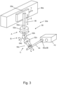
- figure 3 shows the - here identical - gripper guides 32a,b in detail, for example using the gripper guide 32a. Also shown is a section of the crossbeam 46a, on which the carriage 30a is mounted so that it can be moved linearly in the Y spatial direction.
- the gripper guide 32a contains an arm 48 which is mounted so that it can be moved linearly relative to the carriage 30a in a third spatial direction, here the Z spatial direction (again double arrow).
- the Z spatial direction lies outside of the XY plane 36, specifically running perpendicular to it here.
- the gripper 22a is in turn attached to the arm 48 or mounted.
- the gripper 22a is also movably mounted with respect to the carriage 30a with respect to three rotational degrees of freedom AC.
- the rotation guide 50 allows rotation of the gripper 22a by means of three rotary joints 52a-c, which allow a respective rotation (degrees of freedom A-C) about a rotation axis 54a-c.
- figure 3 also shows symbolically how the cable 6c can optionally be stored in a connector housing 70 .
- the connector housing 70 is held on the form board 8 .
- this is only roughly indicated.
- the desired position LS of the cable 6c also consists in the fact that a plug-in section 68 of the cable 6c is plugged into the connector housing 70 at its end section 40a.
- the control device 38 is then set up to control the gripper 22a in such a way that it inserts the plug-in section 68 into the connector housing 70 in order to deposit the cable 6c in the desired position LS.
- figure 4 shows a section of the guide channel 10a representative of all guide channels 10a-c.
- this is formed by lining up respective support points 56 which are fastened to the form board 8 .
- the support points 56 are spaced apart from one another.
- the guide channel 10a is therefore largely an imaginary or immaterial channel; only the support points 56 form its material part.
- the support points 56 are formed by metallic forks with a transverse shelf 57 and two parallel, transversely projecting delineators 59 which together form a groove or U-shape open to the guide side 12, here upwards. These U-shapes stand on the shaped board 8 via support sections or rods of the support points 56, which are not explained in detail.
- the guide channel 10a also has friction-reducing means 60, here on one of the delineators 59. This is set up as follows: when the cable 6a is pulled along the guide channel 10a, its friction on the friction-reducing means 60 is reduced in relation to another material section 62 of the guide channel 10a (transverse shelf 57, other delineator post 59).
- the friction-reducing means 60 is a roller 66 mounted in ball bearings on an axle 64 , which together form the delineator post 59 .
- the remaining material section 62 of the guide channel 10a is formed by the remaining rigid/material parts of the support points 56. If the cable 6a to be pulled is in contact with the rollers 66, it can be pulled through the guide channel 10a with significantly less friction than if it were in contact/rubbing against the other rigid sections 62 of the support points 56.
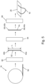
- FIG 5 shows the cable machine 14 in more detail and explains it with reference to the production of the cable 6c.
- the supply of lines 16 contains a very large supply of a respective line 82, for example in the form of a cable drum indicated here.
- the cable machine 14 contains a lengthening module 80, which first cuts/lengthens a piece of a length L that can be predetermined as a line 82 and corresponds to the predetermined length of the cable 6c explained above from the ("endlessly" long) line 82 of the line supply 16.
- the cable machine 14 also contains an assembly module 84. This assembles the cut-to-length line 82 in the present case by stripping the end sections 40a,b of the insulation, twisting its strands and providing them with crimp contacts (not shown) on their plug-in sections 68. Now the cable 6a is completed.
- the cable machine 14 also contains an output module 86. This is used to provide, transport and deposit here, the assembled line 82 or the cable 6c at the preparation station 26 of the depositing machine 20.
- the cable machine 14 has a particularly simple design. This is namely only set up to serially produce only a single cable 6a-c in each case and to make it available to the laying machine 20 at the staging area 26.
Landscapes
- Engineering & Computer Science (AREA)
- Manufacturing & Machinery (AREA)
- Installation Of Indoor Wiring (AREA)
- Laying Of Electric Cables Or Lines Outside (AREA)
- Manufacturing Of Electrical Connectors (AREA)
Priority Applications (2)
| Application Number | Priority Date | Filing Date | Title |
|---|---|---|---|
| MA62682A MA62682B1 (fr) | 2021-10-19 | 2022-08-26 | Système de double préhension de translation pour déposer un faisceau de câbles |
| RS20260243A RS67807B1 (sr) | 2021-10-19 | 2022-08-26 | Translatorni sistem sa dvostrukim hvataljkama za polaganje seta kablova |
Applications Claiming Priority (1)
| Application Number | Priority Date | Filing Date | Title |
|---|---|---|---|
| DE102021127042.1A DE102021127042A1 (de) | 2021-10-19 | 2021-10-19 | Translatorisches Doppelgreifersystem zum Ablegen eines Kabelsatzes |
Publications (2)
| Publication Number | Publication Date |
|---|---|
| EP4170683A1 true EP4170683A1 (fr) | 2023-04-26 |
| EP4170683B1 EP4170683B1 (fr) | 2025-12-17 |
Family
ID=83360900
Family Applications (1)
| Application Number | Title | Priority Date | Filing Date |
|---|---|---|---|
| EP22192258.6A Active EP4170683B1 (fr) | 2021-10-19 | 2022-08-26 | Système de double préhension de translation pour déposer un faisceau de câbles |
Country Status (4)
| Country | Link |
|---|---|
| EP (1) | EP4170683B1 (fr) |
| DE (1) | DE102021127042A1 (fr) |
| MA (1) | MA62682B1 (fr) |
| RS (1) | RS67807B1 (fr) |
Families Citing this family (3)
| Publication number | Priority date | Publication date | Assignee | Title |
|---|---|---|---|---|
| DE102023111521A1 (de) * | 2023-05-04 | 2024-11-07 | Bayerische Motoren Werke Aktiengesellschaft | System zum Herstellen eines aus elektrischen Leitungen gebildeten Kabelbaums sowie Fahrzeug |
| DE102023115809A1 (de) * | 2023-06-16 | 2024-12-19 | Kromberg & Schubert Automotive Gmbh & Co. Kg | Vorrichtung und Verfahren zum Verlegen von Leitungen zur Ausbildung eines Leitungssatzes |
| DE102023118822A1 (de) | 2023-07-17 | 2025-01-23 | Kromberg & Schubert Automotive Gmbh & Co. Kg | Bearbeitungssystem zur Verarbeitung von Leitungen und/oder Herstellung eines Leitungssatzes aus den Leitungen |
Citations (21)
| Publication number | Priority date | Publication date | Assignee | Title |
|---|---|---|---|---|
| US3930524A (en) * | 1974-10-17 | 1976-01-06 | Tarbox John W | Harness making apparatus |
| JPS59221000A (ja) | 1983-05-31 | 1984-12-12 | 三菱電機株式会社 | 自動配線装置 |
| JPS60233898A (ja) | 1984-05-04 | 1985-11-20 | 三菱電機株式会社 | 自動布線方法及びそれに使用する自動布線装置 |
| EP0199653A2 (fr) * | 1985-04-25 | 1986-10-29 | Grumman Aerospace Corporation | Procédé et dispositif pour dénuder des fils de câble et y sertir rapidement des contacts |
| DE3544219A1 (de) | 1985-12-13 | 1987-06-19 | Fraunhofer Ges Forschung | Verfahren und vorrichtung fuer eine kabelbaumfertigungseinrichtung |
| JPS6355819A (ja) | 1986-08-25 | 1988-03-10 | 新明和工業株式会社 | 電線の布線機 |
| JPS6358712A (ja) | 1986-08-29 | 1988-03-14 | 株式会社日立製作所 | 自動布線装置 |
| JPS6378600A (ja) | 1986-09-22 | 1988-04-08 | 株式会社日立製作所 | 布線用ロボツトハンド |
| US4803778A (en) * | 1983-10-07 | 1989-02-14 | The Boeing Company | Method for making a wire harness |
| JPH04236498A (ja) | 1991-01-21 | 1992-08-25 | Nec Corp | ケーブル配線装置 |
| JPH0765652A (ja) | 1993-08-27 | 1995-03-10 | Sumitomo Wiring Syst Ltd | ワイヤーハーネスの製造方法およびその方法を実現するためのワイヤーハーネス製造装置 |
| JPH07223179A (ja) | 1994-02-04 | 1995-08-22 | Toshiba Corp | 複腕ロボット |
| JP2004119444A (ja) | 2002-09-24 | 2004-04-15 | Mitsubishi Heavy Ind Ltd | 自動布線システム |
| EP2784789A1 (fr) * | 2013-03-26 | 2014-10-01 | Airbus Operations (S.A.S) | Dispositif d aide à la fabrication de harnais électriques |
| JP2015220068A (ja) | 2014-05-16 | 2015-12-07 | 矢崎総業株式会社 | ハーネス配索装置及びハーネス配索方法 |
| JP2017148909A (ja) * | 2016-02-25 | 2017-08-31 | セイコーエプソン株式会社 | 制御装置、ロボット、及びロボットシステム |
| DE102016111521A1 (de) | 2016-06-23 | 2017-12-28 | Lisa Dräxlmaier GmbH | Vorrichtung zum Herstellen eines Kabelbaums |
| JP2018005986A (ja) | 2016-06-27 | 2018-01-11 | 矢崎総業株式会社 | ワイヤハーネスの製造装置 |
| DE102016013678A1 (de) | 2016-11-16 | 2018-05-17 | Audi Ag | System zum automatisierten Konfektionieren eines Leitungssatzes |
| WO2019098074A1 (fr) * | 2017-11-16 | 2019-05-23 | 倉敷紡績株式会社 | Procédé de préhension d'objet linéaire et dispositif de commande |
| DE102018115557B3 (de) | 2018-06-28 | 2019-07-04 | Kromberg & Schubert Gmbh & Co. Kg | Automatisierte Leitungsverlegung für Leitungssätze elektrischer Systeme mittels zweier kraftgeregelter Roboter |
Family Cites Families (3)
| Publication number | Priority date | Publication date | Assignee | Title |
|---|---|---|---|---|
| AT410609B (de) | 2000-12-11 | 2003-06-25 | Eltrona Rkt Rottenmanner Kabel | Verfahren zur automatisierten herstellung von kabelbäumen und anlage zur durchführung des verfahrens |
| US9257808B1 (en) | 2010-09-10 | 2016-02-09 | Automated Wiring Systems, LLC | Integrated wire harness batch production with double buffer assembly systems and methods |
| JP2016192135A (ja) * | 2015-03-31 | 2016-11-10 | 株式会社オートネットワーク技術研究所 | 電線群加工用の画像取得システム |
-
2021
- 2021-10-19 DE DE102021127042.1A patent/DE102021127042A1/de active Pending
-
2022
- 2022-08-26 MA MA62682A patent/MA62682B1/fr unknown
- 2022-08-26 RS RS20260243A patent/RS67807B1/sr unknown
- 2022-08-26 EP EP22192258.6A patent/EP4170683B1/fr active Active
Patent Citations (21)
| Publication number | Priority date | Publication date | Assignee | Title |
|---|---|---|---|---|
| US3930524A (en) * | 1974-10-17 | 1976-01-06 | Tarbox John W | Harness making apparatus |
| JPS59221000A (ja) | 1983-05-31 | 1984-12-12 | 三菱電機株式会社 | 自動配線装置 |
| US4803778A (en) * | 1983-10-07 | 1989-02-14 | The Boeing Company | Method for making a wire harness |
| JPS60233898A (ja) | 1984-05-04 | 1985-11-20 | 三菱電機株式会社 | 自動布線方法及びそれに使用する自動布線装置 |
| EP0199653A2 (fr) * | 1985-04-25 | 1986-10-29 | Grumman Aerospace Corporation | Procédé et dispositif pour dénuder des fils de câble et y sertir rapidement des contacts |
| DE3544219A1 (de) | 1985-12-13 | 1987-06-19 | Fraunhofer Ges Forschung | Verfahren und vorrichtung fuer eine kabelbaumfertigungseinrichtung |
| JPS6355819A (ja) | 1986-08-25 | 1988-03-10 | 新明和工業株式会社 | 電線の布線機 |
| JPS6358712A (ja) | 1986-08-29 | 1988-03-14 | 株式会社日立製作所 | 自動布線装置 |
| JPS6378600A (ja) | 1986-09-22 | 1988-04-08 | 株式会社日立製作所 | 布線用ロボツトハンド |
| JPH04236498A (ja) | 1991-01-21 | 1992-08-25 | Nec Corp | ケーブル配線装置 |
| JPH0765652A (ja) | 1993-08-27 | 1995-03-10 | Sumitomo Wiring Syst Ltd | ワイヤーハーネスの製造方法およびその方法を実現するためのワイヤーハーネス製造装置 |
| JPH07223179A (ja) | 1994-02-04 | 1995-08-22 | Toshiba Corp | 複腕ロボット |
| JP2004119444A (ja) | 2002-09-24 | 2004-04-15 | Mitsubishi Heavy Ind Ltd | 自動布線システム |
| EP2784789A1 (fr) * | 2013-03-26 | 2014-10-01 | Airbus Operations (S.A.S) | Dispositif d aide à la fabrication de harnais électriques |
| JP2015220068A (ja) | 2014-05-16 | 2015-12-07 | 矢崎総業株式会社 | ハーネス配索装置及びハーネス配索方法 |
| JP2017148909A (ja) * | 2016-02-25 | 2017-08-31 | セイコーエプソン株式会社 | 制御装置、ロボット、及びロボットシステム |
| DE102016111521A1 (de) | 2016-06-23 | 2017-12-28 | Lisa Dräxlmaier GmbH | Vorrichtung zum Herstellen eines Kabelbaums |
| JP2018005986A (ja) | 2016-06-27 | 2018-01-11 | 矢崎総業株式会社 | ワイヤハーネスの製造装置 |
| DE102016013678A1 (de) | 2016-11-16 | 2018-05-17 | Audi Ag | System zum automatisierten Konfektionieren eines Leitungssatzes |
| WO2019098074A1 (fr) * | 2017-11-16 | 2019-05-23 | 倉敷紡績株式会社 | Procédé de préhension d'objet linéaire et dispositif de commande |
| DE102018115557B3 (de) | 2018-06-28 | 2019-07-04 | Kromberg & Schubert Gmbh & Co. Kg | Automatisierte Leitungsverlegung für Leitungssätze elektrischer Systeme mittels zweier kraftgeregelter Roboter |
Also Published As
| Publication number | Publication date |
|---|---|
| RS67807B1 (sr) | 2026-03-31 |
| DE102021127042A1 (de) | 2023-04-20 |
| MA62682B1 (fr) | 2026-03-31 |
| EP4170683B1 (fr) | 2025-12-17 |
Similar Documents
| Publication | Publication Date | Title |
|---|---|---|
| EP3593420B1 (fr) | Installation et procédé servant à fabriquer de manière automatisée un jeu de câbles | |
| DE102008013591B4 (de) | Werkzeug, Anlage und Verfahren zur Herstellung eines Kabelbaums | |
| DE102017206140B4 (de) | Anlage sowie Verfahren zum automatisierten Herstellen eines Kabelsatzes | |
| EP4170683B1 (fr) | Système de double préhension de translation pour déposer un faisceau de câbles | |
| DE3887406T2 (de) | Verfahren und Vorrichtung zum maschinellen Krimpen eines Verbindungsteiles mit den Enden meherer leitenden Drähte. | |
| DE102018131444A1 (de) | Ablängautomat und modulares Kabelverarbeitungscenter | |
| EP0703646B1 (fr) | Procédé et dispositif pour câbler les bornes de raccordement de composants d'appareils électriques | |
| WO2020187349A1 (fr) | Pince pour le câblage automatisé de composants électriques d'une installation de commutation électrique, robot correspondant et procédé correspondante | |
| DE102017206141B4 (de) | Anlage sowie Verfahren zur automatisierten Vorbereitung und Bereitstellung von einzelnen Leitungselementen für einen Kabelsatz | |
| EP0272395A1 (fr) | Dispositif de transport pour câble électrique | |
| EP0419524B1 (fr) | Procede et dispositif pour la fabrication d'un faisceau de cables | |
| EP1251605B1 (fr) | Appareil et méthode pour l'insertion de bout de câble dans des boítiers de connecteurs | |
| EP1342248B1 (fr) | Procede de production de faisceaux de cables et installation pour la mise en oeuvre de ce procede | |
| DE102019211533B4 (de) | Verteilstation sowie Verfahren zum Betrieb einer Verteilstation für eine automatisierte Herstellung eines Kabelsatzes | |
| DE102004003189A1 (de) | Tuben-Handhabungsvorrichtung und Verfahren zu deren Steuerung | |
| EP2779327B1 (fr) | Pince rotative pour câble et méthode de guidage d'un conducteur électrique | |
| EP0917259B1 (fr) | Procédé et dispositif pour le câblage automatique de bornes de composants d'appareils électriques | |
| DE19756978C1 (de) | Verfahren und Vorrichtung zur Fertigung von Kabelmodulen | |
| EP0444032B1 (fr) | Procede et dispositif de fabrication d'harnais de cables | |
| DE202024002051U1 (de) | Zuführwerkzeug für elektrische Leitungen | |
| WO1989000349A1 (fr) | Unite completement automatique de fabrication et de transfert de cables utilisee pour denuder, fixer et stocker des cables selon la technique de sertissage crimp | |
| DE3820636C2 (fr) | ||
| EP4456341A1 (fr) | Dispositif, installation et procédé d'alimentation d'une ligne électrique | |
| DE102023115809A1 (de) | Vorrichtung und Verfahren zum Verlegen von Leitungen zur Ausbildung eines Leitungssatzes | |
| DE4224194A1 (de) | Verfahren und Vorrichtung zum Konfektionieren von Leitungsbündeln |
Legal Events
| Date | Code | Title | Description |
|---|---|---|---|
| PUAI | Public reference made under article 153(3) epc to a published international application that has entered the european phase |
Free format text: ORIGINAL CODE: 0009012 |
|
| STAA | Information on the status of an ep patent application or granted ep patent |
Free format text: STATUS: THE APPLICATION HAS BEEN PUBLISHED |
|
| AK | Designated contracting states |
Kind code of ref document: A1 Designated state(s): AL AT BE BG CH CY CZ DE DK EE ES FI FR GB GR HR HU IE IS IT LI LT LU LV MC MK MT NL NO PL PT RO RS SE SI SK SM TR |
|
| STAA | Information on the status of an ep patent application or granted ep patent |
Free format text: STATUS: REQUEST FOR EXAMINATION WAS MADE |
|
| 17P | Request for examination filed |
Effective date: 20230921 |
|
| RAV | Requested validation state of the european patent: fee paid |
Extension state: TN Effective date: 20220826 Extension state: MD Effective date: 20230921 Extension state: MA Effective date: 20230921 |
|
| RAX | Requested extension states of the european patent have changed |
Extension state: BA Payment date: 20230921 |
|
| RBV | Designated contracting states (corrected) |
Designated state(s): AL AT BE BG CH CY CZ DE DK EE ES FI FR GB GR HR HU IE IS IT LI LT LU LV MC MK MT NL NO PL PT RO RS SE SI SK SM TR |
|
| TPAC | Observations filed by third parties |
Free format text: ORIGINAL CODE: EPIDOSNTIPA |
|
| STAA | Information on the status of an ep patent application or granted ep patent |
Free format text: STATUS: EXAMINATION IS IN PROGRESS |
|
| 17Q | First examination report despatched |
Effective date: 20241219 |
|
| GRAP | Despatch of communication of intention to grant a patent |
Free format text: ORIGINAL CODE: EPIDOSNIGR1 |
|
| STAA | Information on the status of an ep patent application or granted ep patent |
Free format text: STATUS: GRANT OF PATENT IS INTENDED |
|
| INTG | Intention to grant announced |
Effective date: 20250722 |
|
| GRAS | Grant fee paid |
Free format text: ORIGINAL CODE: EPIDOSNIGR3 |
|
| GRAA | (expected) grant |
Free format text: ORIGINAL CODE: 0009210 |
|
| STAA | Information on the status of an ep patent application or granted ep patent |
Free format text: STATUS: THE PATENT HAS BEEN GRANTED |
|
| AK | Designated contracting states |
Kind code of ref document: B1 Designated state(s): AL AT BE BG CH CY CZ DE DK EE ES FI FR GB GR HR HU IE IS IT LI LT LU LV MC MK MT NL NO PL PT RO RS SE SI SK SM TR |
|
| P01 | Opt-out of the competence of the unified patent court (upc) registered |
Free format text: CASE NUMBER: UPC_APP_0012443_4170683/2025 Effective date: 20251106 |
|
| REG | Reference to a national code |
Ref country code: CH Ref legal event code: F10 Free format text: ST27 STATUS EVENT CODE: U-0-0-F10-F00 (AS PROVIDED BY THE NATIONAL OFFICE) Effective date: 20251217 Ref country code: GB Ref legal event code: FG4D Free format text: NOT ENGLISH Ref country code: TN Ref legal event code: VAGR Ref document number: TN/P/2025/0517 Country of ref document: TN |
|
| REG | Reference to a national code |
Ref country code: DE Ref legal event code: R096 Ref document number: 502022006451 Country of ref document: DE |
|
| REG | Reference to a national code |
Ref country code: MA Ref legal event code: VAGR Ref document number: 62682 Country of ref document: MA Kind code of ref document: B1 |
|
| REG | Reference to a national code |
Ref country code: LT Ref legal event code: MG9D |
|
| PG25 | Lapsed in a contracting state [announced via postgrant information from national office to epo] |
Ref country code: NO Free format text: LAPSE BECAUSE OF FAILURE TO SUBMIT A TRANSLATION OF THE DESCRIPTION OR TO PAY THE FEE WITHIN THE PRESCRIBED TIME-LIMIT Effective date: 20260317 |
|
| PG25 | Lapsed in a contracting state [announced via postgrant information from national office to epo] |
Ref country code: HR Free format text: LAPSE BECAUSE OF FAILURE TO SUBMIT A TRANSLATION OF THE DESCRIPTION OR TO PAY THE FEE WITHIN THE PRESCRIBED TIME-LIMIT Effective date: 20251217 Ref country code: FI Free format text: LAPSE BECAUSE OF FAILURE TO SUBMIT A TRANSLATION OF THE DESCRIPTION OR TO PAY THE FEE WITHIN THE PRESCRIBED TIME-LIMIT Effective date: 20251217 |
|
| REG | Reference to a national code |
Ref country code: NL Ref legal event code: MP Effective date: 20251217 |
|
| PG25 | Lapsed in a contracting state [announced via postgrant information from national office to epo] |
Ref country code: LV Free format text: LAPSE BECAUSE OF FAILURE TO SUBMIT A TRANSLATION OF THE DESCRIPTION OR TO PAY THE FEE WITHIN THE PRESCRIBED TIME-LIMIT Effective date: 20251217 |
|
| PG25 | Lapsed in a contracting state [announced via postgrant information from national office to epo] |
Ref country code: BG Free format text: LAPSE BECAUSE OF FAILURE TO SUBMIT A TRANSLATION OF THE DESCRIPTION OR TO PAY THE FEE WITHIN THE PRESCRIBED TIME-LIMIT Effective date: 20251217 |
|
| PG25 | Lapsed in a contracting state [announced via postgrant information from national office to epo] |
Ref country code: NL Free format text: LAPSE BECAUSE OF FAILURE TO SUBMIT A TRANSLATION OF THE DESCRIPTION OR TO PAY THE FEE WITHIN THE PRESCRIBED TIME-LIMIT Effective date: 20251217 |
|
| PG25 | Lapsed in a contracting state [announced via postgrant information from national office to epo] |
Ref country code: LT Free format text: LAPSE BECAUSE OF FAILURE TO SUBMIT A TRANSLATION OF THE DESCRIPTION OR TO PAY THE FEE WITHIN THE PRESCRIBED TIME-LIMIT Effective date: 20251217 |
|
| PG25 | Lapsed in a contracting state [announced via postgrant information from national office to epo] |
Ref country code: SM Free format text: LAPSE BECAUSE OF FAILURE TO SUBMIT A TRANSLATION OF THE DESCRIPTION OR TO PAY THE FEE WITHIN THE PRESCRIBED TIME-LIMIT Effective date: 20251217 |
|
| PG25 | Lapsed in a contracting state [announced via postgrant information from national office to epo] |
Ref country code: ES Free format text: LAPSE BECAUSE OF FAILURE TO SUBMIT A TRANSLATION OF THE DESCRIPTION OR TO PAY THE FEE WITHIN THE PRESCRIBED TIME-LIMIT Effective date: 20251217 |
|
| PG25 | Lapsed in a contracting state [announced via postgrant information from national office to epo] |
Ref country code: PL Free format text: LAPSE BECAUSE OF FAILURE TO SUBMIT A TRANSLATION OF THE DESCRIPTION OR TO PAY THE FEE WITHIN THE PRESCRIBED TIME-LIMIT Effective date: 20251217 |
|
| PG25 | Lapsed in a contracting state [announced via postgrant information from national office to epo] |
Ref country code: IT Free format text: LAPSE BECAUSE OF FAILURE TO SUBMIT A TRANSLATION OF THE DESCRIPTION OR TO PAY THE FEE WITHIN THE PRESCRIBED TIME-LIMIT Effective date: 20251217 |
|
| VS25 | Lapsed in a validation state [announced via postgrant information from nat. office to epo] |
Ref country code: MD Free format text: LAPSE BECAUSE OF FAILURE TO SUBMIT A TRANSLATION OF THE DESCRIPTION OR TO PAY THE FEE WITHIN THE PRESCRIBED TIME-LIMIT Effective date: 20251217 |
|
| PG25 | Lapsed in a contracting state [announced via postgrant information from national office to epo] |
Ref country code: EE Free format text: LAPSE BECAUSE OF FAILURE TO SUBMIT A TRANSLATION OF THE DESCRIPTION OR TO PAY THE FEE WITHIN THE PRESCRIBED TIME-LIMIT Effective date: 20251217 |
|
| PG25 | Lapsed in a contracting state [announced via postgrant information from national office to epo] |
Ref country code: IS Free format text: LAPSE BECAUSE OF FAILURE TO SUBMIT A TRANSLATION OF THE DESCRIPTION OR TO PAY THE FEE WITHIN THE PRESCRIBED TIME-LIMIT Effective date: 20260417 Ref country code: PT Free format text: LAPSE BECAUSE OF FAILURE TO SUBMIT A TRANSLATION OF THE DESCRIPTION OR TO PAY THE FEE WITHIN THE PRESCRIBED TIME-LIMIT Effective date: 20260417 |
|
| PG25 | Lapsed in a contracting state [announced via postgrant information from national office to epo] |
Ref country code: CZ Free format text: LAPSE BECAUSE OF FAILURE TO SUBMIT A TRANSLATION OF THE DESCRIPTION OR TO PAY THE FEE WITHIN THE PRESCRIBED TIME-LIMIT Effective date: 20251217 |
|
| PG25 | Lapsed in a contracting state [announced via postgrant information from national office to epo] |
Ref country code: SK Free format text: LAPSE BECAUSE OF FAILURE TO SUBMIT A TRANSLATION OF THE DESCRIPTION OR TO PAY THE FEE WITHIN THE PRESCRIBED TIME-LIMIT Effective date: 20251217 |
|
| PG25 | Lapsed in a contracting state [announced via postgrant information from national office to epo] |
Ref country code: SE Free format text: LAPSE BECAUSE OF FAILURE TO SUBMIT A TRANSLATION OF THE DESCRIPTION OR TO PAY THE FEE WITHIN THE PRESCRIBED TIME-LIMIT Effective date: 20251217 |