EP4171667B1 - Traitement de gaz - Google Patents
Traitement de gaz Download PDFInfo
- Publication number
- EP4171667B1 EP4171667B1 EP21739276.0A EP21739276A EP4171667B1 EP 4171667 B1 EP4171667 B1 EP 4171667B1 EP 21739276 A EP21739276 A EP 21739276A EP 4171667 B1 EP4171667 B1 EP 4171667B1
- Authority
- EP
- European Patent Office
- Prior art keywords
- gas
- hydrogen peroxide
- air
- support
- radiation
- Prior art date
- Legal status (The legal status is an assumption and is not a legal conclusion. Google has not performed a legal analysis and makes no representation as to the accuracy of the status listed.)
- Active
Links
Images


Classifications
-
- A—HUMAN NECESSITIES
- A61—MEDICAL OR VETERINARY SCIENCE; HYGIENE
- A61L—METHODS OR APPARATUS FOR STERILISING MATERIALS OR OBJECTS IN GENERAL; DISINFECTION, STERILISATION OR DEODORISATION OF AIR; CHEMICAL ASPECTS OF BANDAGES, DRESSINGS, ABSORBENT PADS OR SURGICAL ARTICLES; MATERIALS FOR BANDAGES, DRESSINGS, ABSORBENT PADS OR SURGICAL ARTICLES
- A61L9/00—Disinfection, sterilisation or deodorisation of air
- A61L9/14—Disinfection, sterilisation or deodorisation of air using sprayed or atomised substances including air-liquid contact processes
-
- A—HUMAN NECESSITIES
- A61—MEDICAL OR VETERINARY SCIENCE; HYGIENE
- A61L—METHODS OR APPARATUS FOR STERILISING MATERIALS OR OBJECTS IN GENERAL; DISINFECTION, STERILISATION OR DEODORISATION OF AIR; CHEMICAL ASPECTS OF BANDAGES, DRESSINGS, ABSORBENT PADS OR SURGICAL ARTICLES; MATERIALS FOR BANDAGES, DRESSINGS, ABSORBENT PADS OR SURGICAL ARTICLES
- A61L9/00—Disinfection, sterilisation or deodorisation of air
- A61L9/16—Disinfection, sterilisation or deodorisation of air using physical phenomena
- A61L9/18—Radiation
- A61L9/20—Ultraviolet radiation
Definitions
- the invention relates to a device for treating gases, in particular air, and a corresponding method.
- CN 208809155 U refers to an air disinfection device for infectious diseases, which includes a vertical closed cabinet body, and the cabinet body is provided with an air inlet device, an oxidation/disinfection device, an anion sterilization device, an ultraviolet sterilization device, and an outlet device from top to bottom.
- station air is fed into the oxidation ventilation sterilization device for ventilation through the air inlet device; hydrogen peroxide in the hydrogen peroxide pool can mainly oxidize and disinfect air; then the air flows through the fiber net loaded with the nano-scale antibacterial anion to be disinfected and disinfected again.
- CN 107433078 A relates to an air purification device comprising a large fiber filtration screen, an activated carbon filtration screen and a fan, the activated carbon filtration screen being connected to the fan, the air purification device further comprising a wet filter having a porous structure and positioned between the large fiber filtration screen and the activated carbon filtration screen, an active oxygen substance generator positioned on the upstream side of the wet filter and an ionic liquid.
- the active oxygen substance generator is used to generate active oxygen substances.
- the air purification device can maintain the activity of the active oxygen substance in the ionic liquid for a long time to improve the purification efficiency.
- KR 101708799 B1 a disinfection and purification device using hydroxyl radicals, comprising: a housing having a space unit; a cartridge formed on a bottom of a space unit of the housing and accommodating a hydrogen peroxide solution; and an ultrasonic wave vibrator that converts the hydrogen peroxide solution into a hydrogen peroxide aerosol and disperses it on a top of the space unit of the housing.
- a liquid-phase hydrogen peroxide solution is converted into an aerosol having micro-sized droplets using the ultrasonic wave vibrator and irradiated with ultrasonic waves so that a contact area of a hydrogen peroxide solution and ultrasonic waves is increased.
- the efficiency of the hydroxyl radicals for sterilizing and purifying air can be increased.
- CN 104501338 A discloses an air filter comprising a shell, a filter core and a fan.
- the filter core is mounted in the shell; an air inlet is formed on the right side of the shell; an air inlet is formed on the left side of the shell; the fan is mounted in the shell and positioned on the left side of the shell.
- An air inlet comprising a filter core follows a low-efficiency filter screen, an electrostatic dust chamber, a hydrogen peroxide purification system and a nano-activated carbon filter screen from left to right.
- the hydrogen peroxide purification system comprises an anti-oxidation filter textile microfiber screen that is soaked with hydrogen peroxide. This is said to have the advantage that with the help of the hydrogen peroxide, bacteria and germs can be effectively removed and secondary pollution avoided. Oxygen sources and Humidity is provided so that the air is more dynamic and the nano activated carbon filter screen effectively absorbs the smell of hydrogen peroxide.
- KR 20090081930 A provides an OH radical generating device for effectively oxidizing, decomposing and disinfecting contaminants such as volatile organic compounds and the like in the air by applying a reflective film, high gloss (ALU coated) to an inner surface of a casing and arranging light in a wavelength range used in the photoreaction in the longitudinal direction in the center of the casing.
- An OH radical generating device comprises: a casing forming an external appearance of the OH radical generator having an inlet and an outlet respectively formed on the front and rear sides thereof and an inner peripheral surface of which is covered with a film coating layer, a hydrogen peroxide generator having a nozzle arranged to communicate with the inlet and passing through the casing; and a UV tube floating from a carrier in the housing and vaporizing hydrogen peroxide flowing into the inlet of the hydrogen peroxide generator, thereby generating OH radicals between the UV tube and the film coating to decompose and oxidize and sterilize air sucked into the housing and discharging the sterilized air to the outside through the outlet.
- CN 100393361 C concerns a wall-mounted air decontamination device for preventing respiratory infections.
- the air inlet on the housing is equipped with air inlet louvers.
- the upper part of the shell is equipped with an air outlet pipe.
- the left inside of the shell is equipped with a motor with adjustable speed.
- the drive shaft is connected to a motor with adjustable speed via a belt. speed connected.
- the space for an antiseptic solution on the right inner side of the shell is equipped with an antiseptic solution, a guide shaft and a driven shaft.
- the drive shaft, the driven shaft and the guide shaft are equipped with a disinfection belt.
- the right side of the shell is equipped with a solution injection valve and a level control.
- the lower part of the right side is equipped with a solution outlet valve.
- the inner right side is equipped with power for UV lamps.
- Air inlet louvers are equipped with a photocatalysis net and an electrothermal quartz tube.
- the photocatalysis net is equipped with a UV tube.
- An air outlet photocatalysis net is equipped in a shell.
- the air outlet is equipped with an activated carbon filter blanket and an axial fan. It can be used for disinfection of the ward and operating room, laboratories, public buildings and transportation, waiting rooms, as well as meeting rooms.
- US 6,969,486 B1 describes a device for treating pollutants in a gas, particularly air, and comprises a hydrogen peroxide source and a treatment injector for generating and injecting dissociated hydrogen peroxide into the gas-air stream.
- the treatment injector may further comprise an injector housing having an inlet, an outlet, and a hollow interior therebetween.
- the inlet may be connected in fluid communication with the hydrogen peroxide source so that hydrogen peroxide flows through the hollow interior and toward the outlet.
- At least one UV tube may be positioned within the hollow interior of the injector housing.
- the at least one UV tube may catalyze the hydrogen peroxide flowing through the tube.
- the catalyzed hydrogen peroxide may be injected from the outlet into the gas stream to treat pollutants such as nitrogen oxides.
- US 2007/0217944 A1 comprises a method and apparatus for neutralizing pathogens and chemical toxins in the air, in ventilated air and in heating or air conditioning systems.
- the Pathogen Chemical Toxin Neutralization System is effective against a broad spectrum of pathogens and toxins, contains commercially available components, and can be easily integrated into commercial HVAC systems where large volumes of ventilated air are decontaminated in real time without chemical reagents.
- the system features a flow-through reaction chamber containing at least one UV light source that emits short intense flashes of broad spectrum UV energy, a source of aqueous hydrogen peroxide, which can be a reservoir or a hydrogen peroxide generator, and an ozone source, if required.
- UV light and hydrogen peroxide produces hydroxyl radicals that neutralize pathogens and chemical toxins as they pass through the reaction chamber in real time.
- Pathogens that can be neutralized by this system include bacteria, viruses, spores, fungi, and parasites.
- Hydrogen peroxide is fed into an irradiation chamber in which "short, intense flashes" form corresponding hydroxyl radicals.
- the interaction of UV light and hydroxyl radicals is intended to neutralize the pathogenic and chemical poisons.
- the aqueous peroxide solution is provided as sprayed droplets, as a fine mist or as steam through the nozzle.
- the H 2 O 2 is generated by an electrical discharge under water.
- possibilities of removing ozone from the air are mentioned, the same is explained in more detail in [0070].
- a peroxide concentration of 15% is specified.
- the porous membrane 107 is intended to serve to form additional surfaces on which the free radicals are supposed to react with the pathogens.
- the radicals are directly destroyed on such a surface and thus do not develop any reactivity, especially since the hydroxyl radicals are known to have a half-life of only 1 ns max., which in turn is understandably certainly not sufficient for the disinfection or deactivation of microorganisms.
- WO 2015/059336 A1 relates to a device for purifying air by emitting hydroxyl radicals, comprising: a body provided with a first housing for a first replaceable cartridge.
- the first replaceable cartridge and means for causing the emanation of the reactant from the first cartridge are characterized in that the first cartridge contains a reactant capable of generating hydroxyl radicals by reaction with UV energy, and that the device comprises a UV ray generator.
- UV energy is basically possible in various ways.
- the most efficient method today is the generation via a mercury vapor discharge.
- mercury (Hg) is evaporated in a reaction chamber filled with noble gas by means of active heat supply.
- the electrons of the mercury atoms are then excited by the supply of electrical energy. When these then fall back to their stable energy level, they release the previously supplied energy primarily in the form of UV energy.
- the radiation level or the measurable spectral energy distribution emitted by the plasma, depends primarily on the amount of free mercury atoms, the gas pressure ratio and the level of energy supplied.
- UV-C energy (especially the emission line of mercury vapor at 253.652 nm, which can be excited at low vapor pressure with high yield (30 to 40% of the applied electrical power)) is used in physical disinfection technology (see also mercury vapor lamps). While at 280 nm (absorption maximum of most proteins) the amino acid tryptophan absorbs the ultraviolet radiation, at 265 nm nucleic acids are most damaged. At around 245 nm it is mainly the nucleic acids that absorb, while proteins show a relative absorption minimum between the absorption maximum at around 280 nm by aromatic amino acids (tryptophan, tyrosine and phenylalanine) and the absorption by the peptide bond between the individual amino acids (maximum at around 220 nm). Therefore, at 254 nm (primary radiation of the low-pressure mercury vapor discharge) it is also possible to irradiate protein solutions (such as animal sera for cell culture) to inactivate viruses and bacteria contained therein.
- protein solutions such as animal sera
- UV-C energy For almost all microorganisms, the lethal dose of UV-C energy is known, above which the cell loses its reproductive capacity, is inactivated and no self-repair mechanisms can be activated.
- the lethal dose varies depending on the cell structure. Pathogenic germs and yeasts are extremely sensitive to UV-C. Some mold spores require a higher UV dose. This must be taken into account in the design if necessary.
- a sufficiently high UV dose must be present to ensure an appropriate disinfection performance in the defined irradiation time using a built-in operating hour counter.
- the lethal dose varies depending on the microorganism and cell structure/cell type. Pathogenic germs are very sensitive to UV-C and are inactivated very quickly. Mold spores require a higher UV dose. In practice, for example, a germ reduction of 99.5% to 99.9% is achieved within 2 seconds with sealing films for yogurt cups.
- Every UV radiation source has an electrical power consumption, part of which is emitted in the UV-C range. 90% of the radiation emitted in the UV-C range is generated at 254 nm, the wavelength that is effective for disinfection. This is called the radiation dose.
- the radiation dose is the energy that is emitted by the lamp per unit of time.
- the irradiance or intensity is the radiation dose per unit area (cm 2 ).
- gas refers to any gas or gas mixture, in particular air, but also exhaust air from devices or apparatus.
- the essential core of the present invention is that hydrogen peroxide and/or peracids are applied to a solid carrier and thus act oxidatively and not via the corresponding radicals.
- a wet filter (carrier 3) is loaded with peroxide on the surface, which is absorbed by the air flowing through.
- the device and the method according to the invention can be operated not only with hydrogen peroxide, but preferably with a special cleaning solution containing, for example, 3% by weight peracetic acid, which has a significantly better efficiency than conventional hydrogen peroxide, especially at room temperature. It also allows The invention works with ethanol and/or propanol as solvent for the peroxide, and mixtures thereof.
- viruses and bacteria are inactivated and odors and solvent vapors are neutralized.
- the system is self-regulating and does not require any special settings from the operator.
- the carrier (3) (wet filter) loaded with H 2 O 2 and/or alcohol is able to inactivate existing microorganisms, bacteria and germs as soon as the air/gas flow enters.
- the UV flashes mentioned in the state of the art are certainly not effective, which is why we work with permanent UV-C irradiation.
- the focus is on the filtration and elimination of pigment dirt, dust and microbiological pathogens.
- a further preferred embodiment of the invention is characterized in that the flow machine (4) is arranged in the area of the irradiation chamber (5), in particular in the area of the UV-C lamps (6), but particularly preferably in the area of the exit of the irradiation chamber (5).
- This arrangement of the components has the advantage that the surface of the flow machine (4) only comes into contact with the treated gas flow (2) with a low cleaning agent concentration and low other load on the gas flow.
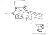
- a view of a corresponding device (1) is shown.
- This essentially consists of a solid carrier (3), the surface of which, in particular the inner surface, is coated with hydrogen peroxide, in particular an aqueous solution.
- the carrier (3) can also have a surface coating of an alcoholic hydrogen peroxide solution. Both alternatives have a certain biocidal, bactericidal and/or virucidal effect, which in itself is already suitable for cleaning the gas to be treated, in particular air.
- the gas flow is guided over the surface of the carrier (3) by means of a flow machine (4), for example a fan.
- a flow machine (4) for example a fan.
- the arrangement of the sequence of the carrier (3) and the flow machine (4) can be freely selected. If the gas flow is first guided through the flow machine (4) and then over the carrier (3), the flow machine (4), for example a fan, does not come into contact with the hydrogen peroxide. This can simplify the selection of the surface properties of the flow machine (4).
- the material of the carrier (3) or its surface can be designed in a variety of ways. A prerequisite is naturally a certain stability to hydrogen peroxide or the corresponding solvent.
- the structure of the carrier (3) comprises a ceramic, a woven fabric, a knitted fabric, a knitted fabric, a scrim, a fleece and/or a nonwoven.
- peracids can also be used in the context of the present invention to load the carrier.
- peracids include, for example, peracetic acid, peroctanoic acid, pernonanoic acid and ⁇ -phthalamide-peroxo-caproic acid. Mixtures of these with one another and with hydrogen peroxide can also be used according to the invention.
- the carrier (3) is loaded with hydrogen peroxide and/or peracids in a solvent.
- the solvent preferably comprises water and/or alcohol, in particular ethanol and/or i-propanol.
- the connection of the carrier (3) to the storage container (7) is shown.
- the latter can be filled with hydrogen peroxide or an aqueous solution thereof.
- the hydrogen peroxide and/or the peracids can reach the surface of the carrier (3) through a connecting line (8) from the storage container (7), which is located, for example, in an open vessel.
- the amount of hydrogen peroxide and/or the peracids can be metered in a simple manner using a hose pump or other metering device.
- Fig. 1 In the enlarged view, the storage container (7) is shown, which is connected here via the connecting line 8 to wet the surface of the carrier (3).
- the size of the storage container (7) depends on the desired application and in particular the volume of the gas flow.
- the connecting line (8) between the storage container (7) and the carrier (3) comprises a metering device (9) for regulating the flow rate of the hydrogen peroxide and/or the peracids or the corresponding solution.
- a peristaltic pump is particularly suitable for this purpose.
- the gas stream flows through the carrier (3) and comes into contact with the hydrogen peroxide and/or the peracids or the corresponding solution. It has been shown that the hydrogen peroxide or the corresponding solution can act as an oxidizing agent for the contamination and thus clean the gas stream 2. Hydroxyl radicals can practically not form here.
- the simplest flow machine (4) for the gas stream is a fan or a compressor. Both terms are used synonymously here.
- the gas stream is then guided into an irradiation area (5) which is equipped with at least one UV tube (6).
- the inventive irradiation of the peroxide-containing gas stream with UV-C radiation creates OH radicals.
- the OH radicals formed improve gas purification.
- the irradiation makes it possible to improve the utilization of the hydrogen peroxide by converting unused H 2 O 2 into OH radicals. This improves the disinfection effect of the peroxide.
- the UV tube (6) is particularly suitable for continuously emitting UV-C radiation.
- the UV-C radiation also has a direct disinfecting effect on the gas flow in the sense of physical disinfection.
- UV radiation is understood here to mean electromagnetic radiation with a wavelength in the range of 1 nm to 400 nm, in particular 100 to 400 nm.
- the spectrum of UV rays is further subdivided into UVA (315 nm to 380 nm), UVB (280 nm to 315 nm) and UVC radiation (100 nm to 280 nm).
- UVA 315 nm to 380 nm
- UVB 280 nm to 315 nm
- UVC radiation 100 nm to 280 nm
- the UV spectrum below 100 nm is referred to as extreme UV.
- the spectrum of X-rays begins below a wavelength of 0.25 nm.
- the UV radiation source comprises a mercury vapor tube and/or one or more UVC LEDs, in particular in the form of a strip attachment.
- UVC LEDs are not only a very long service life, but also the very small component size and simple, low-consumption electronics, which enable uncomplicated device construction.
- any UV radiation source known in the state of the art can be used.
- the UV radiation source is preferably installed immediately upstream of the last component of the carrier (3) or the turbomachine (4).
- the wavelength of the UV radiation emitted by the UV radiation source is preferably in a range from 240 to 260 nm, particularly preferably 254 to 260 nm, in particular 254 to 258 nm.
- the radiation dose is preferably in a range from 200 nm to 300 nm, particularly preferably in a range from 254 nm to 260 nm, in particular 254 nm to 258 nm.
- radiation sources with a long service life are used, in particular up to 12,000 operating hours with 18,000 ignitions.
- the UV radiation source can have an adjustable radiation intensity.
- the UV radiation source is provided with a shield.
- the emitted radiation can be controlled and, in particular, the user of the device according to the invention can be prevented from being exposed to UV radiation.
- the shield can be implemented in particular by means of a stainless steel sheet.
- UVC radiation also has the particular advantage that it has a strong germicidal, bactericidal and virucidal effect in the range of a wavelength of 250 nm to 270 nm, especially in the range around 258 nm. This property can be attributed to the fact that the short-wave and high-energy UVC radiation stops the maintenance of metabolism and cell division by damaging the DNA, so that cells damaged in this way ultimately die.
- the radiation intensity is preferably in a range from 100 nm to 300 nm, particularly preferably in a range from 240 nm to 260 nm, in particular 254 nm to 260 nm.
- the dose is given in ⁇ W*s/cm 2 , often also in J/m 2 .
- the device and the method according to the invention can be used, for example, to improve hygiene in hospitals and nursing homes, hotels and restaurants, in public facilities, such as public toilets in particular, but also in private households. particularly in animal husbandry, as well as in the private sector for allergies, such as those against house dust mites, animal hair and the like.
- the invention can be used to ensure the quality of hygiene in industry, pharmacy and medicine.
- the device (1) makes use of the fact that the gas stream only remains in it for a short time.
- the radicals formed by means of UV-C radiation generally only have a short lifespan.
- the formation of free radicals then takes place directly in the device (1). This procedure offers the particular advantage that the disinfecting effect of the UV energy itself acts directly on the gas stream, in particular the air stream.
- UVC radiation also has the special advantage that it has a strong germicidal, bactericidal and virucidal effect in the range of a wavelength of 250 nm to 270 nm, especially in the range around 258 nm.
- This property can be attributed to the fact that the short-wave and high-energy UVC radiation stops the maintenance of metabolism and cell division by damaging the DNA, so that cells or viruses damaged in this way ultimately die. The formation of resistance due to mutations is excluded.
- This disinfecting effect decreases with increasing complexity of the attacked organisms. Viruses and bacteria are much easier to destroy than fungi or fungal spores, for example. Since UVC rays do not penetrate solid materials, safe shielding is easy to achieve.
- a further preferred embodiment of the invention is characterized in that the flow machine (4) is arranged in the area of the irradiation chamber (5), in particular in the area of the UV lamps (6), but particularly preferably in the area of the exit of the irradiation chamber (5).
- This arrangement of the components has the advantage that the surface of the flow machine (4) only comes into contact with the treated gas flow at a low peroxide concentration and low other load on the gas flow.
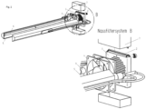
- Fig. 2 shows a different perspective view of the Fig. 1 with a detailed section B of a possible arrangement in the flow direction of the carrier (3), followed by the flow machine (4) and the irradiation room (5), which is equipped with the UV tubes (6).
- FIG. 3 and 4 a front view and a side view of the device according to the invention are shown.
- a further embodiment of the present invention also consists in a method for treating gases, in particular air, using a device as described above, which is characterized in that the gas to be treated is passed over a carrier (3) loaded with hydrogen peroxide and/or peracids with a flow machine (4) into an irradiation chamber (5) with a UV-C light source (6).
- the UV-C light source in the irradiation chamber (5) is operated continuously so that the irradiation chamber (5) is continuously irradiated with UV-C radiation.
- a particle filter is arranged in the area of the gas inlet (2), in particular between the gas inlet (2) and the carrier (3).
- a particle filter can ensure that no solid contaminants are introduced into the system, which could lead to a reduction in the disinfection or cleaning performance. If particle-containing contaminants containing heavy metals penetrate the system, a catalytic effect can occur. In this way, the efficiency of the disinfection can be impaired.
- a particle filter it has been shown that these disadvantages, which also affect air disinfection devices from the prior art in particular, can be avoided by the preferred use of a particle filter.
- the device according to the invention has a bacteria-inhibiting inner coating.
- the device according to the invention can in particular be designed as a mobile system.
- the device according to the invention can not only inactivate germs, in particular bacteria and viruses, but also neutralize odors and solvent vapors.
Landscapes
- Health & Medical Sciences (AREA)
- Epidemiology (AREA)
- Life Sciences & Earth Sciences (AREA)
- Animal Behavior & Ethology (AREA)
- General Health & Medical Sciences (AREA)
- Public Health (AREA)
- Veterinary Medicine (AREA)
- Disinfection, Sterilisation Or Deodorisation Of Air (AREA)
- Apparatus For Disinfection Or Sterilisation (AREA)
Claims (11)
- Dispositif (1) pour traiter des gaz, comprenanta) une entrée de gaz (2) pour un courant du gaz à traiter,b) un support solide perméable aux gaz (3) dont la surface est chargée avec du peroxyde d'hydrogène ou des peracides, dans lequel ledit support (3) comprend une céramique, un tissu tissé, tricot, tissu de mailles, natte, tissu non tissé, et/ou nappe,c) une machine à flux (4) pour transporter ledit flux de gaz à partir de l'entrée de gaz à travers le support (3) dansd) une chambre d'irradiation (5) avec une source de lumière UV-C (6).
- Dispositif selon la revendication 1, caractérisé en ce que ladite machine à flux (4) comprend un ventilateur.
- Dispositif selon l'une des revendications 1 ou 2, caractérisé en ce que ladite machine à flux (4) est située en amont ou en aval du support (3) dans l'écoulement du flux du gaz à traiter.
- Dispositif selon l'une quelconque des revendications 1 à 3, caractérisé en ce que ladite machine à flux (4) est située dans la région de la chambre d'irradiation (5).
- Dispositif selon la revendication 4, caractérisé en ce que ladite machine à flux (4) est située dans la région de la sortie de la chambre d'irradiation (5).
- Dispositif selon l'une quelconque des revendications 1 à 5, caractérisé en ce que ledit support (3) est relié avec un réservoir (7) par une ligne de raccordement (8) pour mouiller la surface du support (3).
- Dispositif selon la revendication 6, caractérisé en ce que ladite ligne de raccordement (8) comprend un moyen de dosage, notamment une pompe péristaltique (9).
- Dispositif selon l'une quelconque des revendications 1 à 7, caractérisé en ce que ledit support (3) est chargé avec des peracides, notamment des peracides dissouts dans un solvant.
- Dispositif selon l'une quelconque des revendications 1 à 8, caractérisé en ce qu'il présente un filtre à particules dans la région de l'entrée de gaz (2).
- Procédé pour traiter des gaz en utilisant un dispositif selon l'une quelconque des revendications 1 à 9, caractérisé en ce que le gaz à traiter est passé par un support (3) chargé avec du peroxyde d'hydrogène et/ou des peracides au moyen d'une machine à flux (4) dans une chambre d'irradiation (5) avec une source de lumière UV-C (6).
- Procédé selon la revendication 10, caractérisé en ce que de l'air est utilisé comme gaz.
Applications Claiming Priority (2)
| Application Number | Priority Date | Filing Date | Title |
|---|---|---|---|
| DE102020116666.4A DE102020116666A1 (de) | 2020-06-24 | 2020-06-24 | Behandlung von Gasen |
| PCT/EP2021/067094 WO2021259976A1 (fr) | 2020-06-24 | 2021-06-23 | Traitement de gaz |
Publications (3)
| Publication Number | Publication Date |
|---|---|
| EP4171667A1 EP4171667A1 (fr) | 2023-05-03 |
| EP4171667C0 EP4171667C0 (fr) | 2025-02-26 |
| EP4171667B1 true EP4171667B1 (fr) | 2025-02-26 |
Family
ID=76829508
Family Applications (1)
| Application Number | Title | Priority Date | Filing Date |
|---|---|---|---|
| EP21739276.0A Active EP4171667B1 (fr) | 2020-06-24 | 2021-06-23 | Traitement de gaz |
Country Status (3)
| Country | Link |
|---|---|
| EP (1) | EP4171667B1 (fr) |
| DE (1) | DE102020116666A1 (fr) |
| WO (1) | WO2021259976A1 (fr) |
Citations (2)
| Publication number | Priority date | Publication date | Assignee | Title |
|---|---|---|---|---|
| CN1692948A (zh) * | 2005-04-22 | 2005-11-09 | 姜天华 | B超探头消毒机 |
| CN201077544Y (zh) * | 2007-05-18 | 2008-06-25 | 上海天龙包装机械成套设备有限公司 | 双氧水杀菌与无菌风装置 |
Family Cites Families (10)
| Publication number | Priority date | Publication date | Assignee | Title |
|---|---|---|---|---|
| US6969486B1 (en) | 2001-02-07 | 2005-11-29 | The United States Of America As Represented By The Administrator Of The National Aeronautics And Space Administration | Apparatus and method for treating pollutants in a gas using hydrogen peroxide and UV light |
| WO2004062800A1 (fr) | 2003-01-06 | 2004-07-29 | The Johns Hopkins University | Decontamination induite par des radicaux libres hydroxyle de spores, de virus et de bacteries aeriens dans un systeme dynamique |
| US8298482B2 (en) * | 2005-06-10 | 2012-10-30 | S.C. Johnson & Son, Inc. | Vapor phase hydrogen peroxide deodorizer |
| CN100393361C (zh) | 2006-04-28 | 2008-06-11 | 陕西师范大学 | 呼吸传染病房壁挂式空气消毒装置 |
| KR20090081930A (ko) | 2008-01-25 | 2009-07-29 | 김건신 | Oh 라디칼 생성장치 |
| ES1092731Y (es) | 2013-10-23 | 2014-02-03 | Juaneda John Morton | Dispositivo de purificacion de aire por emision de radicales hidroxilo |
| CN104501338A (zh) | 2014-12-31 | 2015-04-08 | 安徽省元琛环保科技有限公司 | 一种空气净化装置 |
| CN107433078A (zh) | 2016-05-27 | 2017-12-05 | 深圳市汇清科技有限公司 | 空气净化装置 |
| KR101708799B1 (ko) | 2016-07-21 | 2017-02-22 | 한국철도기술연구원 | 히드록실 라디칼을 이용한 살균 정화 장치 |
| CN208809155U (zh) | 2018-03-20 | 2019-05-03 | 张树武 | 传染病病房空气消毒装置 |
-
2020
- 2020-06-24 DE DE102020116666.4A patent/DE102020116666A1/de not_active Withdrawn
-
2021
- 2021-06-23 EP EP21739276.0A patent/EP4171667B1/fr active Active
- 2021-06-23 WO PCT/EP2021/067094 patent/WO2021259976A1/fr not_active Ceased
Patent Citations (2)
| Publication number | Priority date | Publication date | Assignee | Title |
|---|---|---|---|---|
| CN1692948A (zh) * | 2005-04-22 | 2005-11-09 | 姜天华 | B超探头消毒机 |
| CN201077544Y (zh) * | 2007-05-18 | 2008-06-25 | 上海天龙包装机械成套设备有限公司 | 双氧水杀菌与无菌风装置 |
Also Published As
| Publication number | Publication date |
|---|---|
| WO2021259976A1 (fr) | 2021-12-30 |
| EP4171667A1 (fr) | 2023-05-03 |
| EP4171667C0 (fr) | 2025-02-26 |
| DE102020116666A1 (de) | 2021-12-30 |
Similar Documents
| Publication | Publication Date | Title |
|---|---|---|
| DE102005003923A1 (de) | Vorrichtung und Verfahren zum Entkeimen von Raumluft | |
| DE69527086T2 (de) | Verfahren und vorrichtung zur behandlung von flüssigkeiten | |
| EP2968632B1 (fr) | Procédé pour l'application ciblée de biocide en phase gazeuse | |
| US20060104858A1 (en) | Hydroxyl free radical-induced decontamination of airborne spores, viruses and bacteria in a dynamic system | |
| KR101785093B1 (ko) | 살균 장치 | |
| EP1986703A1 (fr) | Systeme d'elimination de contaminants atmospheriques | |
| JPH10253096A (ja) | 殺菌・脱臭手段を備えた空調装置 | |
| DE102010052053A1 (de) | Vorrichtung und Verfahren zur Entkeimung strömender Luft | |
| EP1436025B1 (fr) | Dispositif de traitement de liquides aqueux | |
| WO2018066622A1 (fr) | Appareil de traitement par décharge et unité de traitement par décharge associée | |
| DE102018125596A1 (de) | Vorrichtung und Verfahren zur Entkeimung eines Gases oder Gasgemisches mit UVC-Strahlung | |
| US20120189490A1 (en) | Cleansing system using ozone and nebulized fluids | |
| DE102021000458A1 (de) | Luftsterilisator | |
| KR20210047548A (ko) | 오존 및 oh 라디칼을 이용한 축사용 공기정화 시스템 | |
| WO2012103010A1 (fr) | Système de nettoyage utilisant de l'ozone et des fluides nébulisés | |
| JP3364708B2 (ja) | 空調装置 | |
| WO2018007557A1 (fr) | Dispositif de désinfection et procédé de désinfection | |
| EP4171667B1 (fr) | Traitement de gaz | |
| DE102018010294B4 (de) | Verfahren und Vorrichtung zur Reinigung und Desinfizierung von Textilien | |
| DE102020204403B4 (de) | Vorrichtung zur Desinfektion von Luft in/an Atemschutzmaske oder Beatmungsgerät | |
| EP3964760A1 (fr) | Système de traitement de l'air permettant de nettoyer l'air ambiant | |
| DE102021105374A1 (de) | Luftaufbereitungsapparat | |
| RU2386451C2 (ru) | Способ обеззараживания воздуха в помещениях | |
| EP4000656B1 (fr) | Dispositif et procédé de réduction de la charge en substances nocives dans un gaz | |
| EP4157441A1 (fr) | Dispositif d'application de rayonnement à usage médical et cosmétique sur un corps humain ou sur des parties d'un corps humain |
Legal Events
| Date | Code | Title | Description |
|---|---|---|---|
| STAA | Information on the status of an ep patent application or granted ep patent |
Free format text: STATUS: UNKNOWN |
|
| STAA | Information on the status of an ep patent application or granted ep patent |
Free format text: STATUS: THE INTERNATIONAL PUBLICATION HAS BEEN MADE |
|
| PUAI | Public reference made under article 153(3) epc to a published international application that has entered the european phase |
Free format text: ORIGINAL CODE: 0009012 |
|
| STAA | Information on the status of an ep patent application or granted ep patent |
Free format text: STATUS: REQUEST FOR EXAMINATION WAS MADE |
|
| 17P | Request for examination filed |
Effective date: 20230110 |
|
| AK | Designated contracting states |
Kind code of ref document: A1 Designated state(s): AL AT BE BG CH CY CZ DE DK EE ES FI FR GB GR HR HU IE IS IT LI LT LU LV MC MK MT NL NO PL PT RO RS SE SI SK SM TR |
|
| DAV | Request for validation of the european patent (deleted) | ||
| DAX | Request for extension of the european patent (deleted) | ||
| STAA | Information on the status of an ep patent application or granted ep patent |
Free format text: STATUS: EXAMINATION IS IN PROGRESS |
|
| 17Q | First examination report despatched |
Effective date: 20231122 |
|
| GRAP | Despatch of communication of intention to grant a patent |
Free format text: ORIGINAL CODE: EPIDOSNIGR1 |
|
| STAA | Information on the status of an ep patent application or granted ep patent |
Free format text: STATUS: GRANT OF PATENT IS INTENDED |
|
| INTG | Intention to grant announced |
Effective date: 20241106 |
|
| GRAS | Grant fee paid |
Free format text: ORIGINAL CODE: EPIDOSNIGR3 |
|
| GRAA | (expected) grant |
Free format text: ORIGINAL CODE: 0009210 |
|
| STAA | Information on the status of an ep patent application or granted ep patent |
Free format text: STATUS: THE PATENT HAS BEEN GRANTED |
|
| AK | Designated contracting states |
Kind code of ref document: B1 Designated state(s): AL AT BE BG CH CY CZ DE DK EE ES FI FR GB GR HR HU IE IS IT LI LT LU LV MC MK MT NL NO PL PT RO RS SE SI SK SM TR |
|
| REG | Reference to a national code |
Ref country code: GB Ref legal event code: FG4D Free format text: NOT ENGLISH |
|
| REG | Reference to a national code |
Ref country code: CH Ref legal event code: EP |
|
| REG | Reference to a national code |
Ref country code: DE Ref legal event code: R096 Ref document number: 502021006795 Country of ref document: DE |
|
| REG | Reference to a national code |
Ref country code: IE Ref legal event code: FG4D Free format text: LANGUAGE OF EP DOCUMENT: GERMAN |
|
| U01 | Request for unitary effect filed |
Effective date: 20250326 |
|
| U07 | Unitary effect registered |
Designated state(s): AT BE BG DE DK EE FI FR IT LT LU LV MT NL PT RO SE SI Effective date: 20250401 |
|
| U20 | Renewal fee for the european patent with unitary effect paid |
Year of fee payment: 5 Effective date: 20250515 |
|
| PG25 | Lapsed in a contracting state [announced via postgrant information from national office to epo] |
Ref country code: RS Free format text: LAPSE BECAUSE OF FAILURE TO SUBMIT A TRANSLATION OF THE DESCRIPTION OR TO PAY THE FEE WITHIN THE PRESCRIBED TIME-LIMIT Effective date: 20250526 |
|
| PG25 | Lapsed in a contracting state [announced via postgrant information from national office to epo] |
Ref country code: PL Free format text: LAPSE BECAUSE OF FAILURE TO SUBMIT A TRANSLATION OF THE DESCRIPTION OR TO PAY THE FEE WITHIN THE PRESCRIBED TIME-LIMIT Effective date: 20250226 |
|
| PG25 | Lapsed in a contracting state [announced via postgrant information from national office to epo] |
Ref country code: ES Free format text: LAPSE BECAUSE OF FAILURE TO SUBMIT A TRANSLATION OF THE DESCRIPTION OR TO PAY THE FEE WITHIN THE PRESCRIBED TIME-LIMIT Effective date: 20250226 |
|
| PG25 | Lapsed in a contracting state [announced via postgrant information from national office to epo] |
Ref country code: IS Free format text: LAPSE BECAUSE OF FAILURE TO SUBMIT A TRANSLATION OF THE DESCRIPTION OR TO PAY THE FEE WITHIN THE PRESCRIBED TIME-LIMIT Effective date: 20250626 Ref country code: NO Free format text: LAPSE BECAUSE OF FAILURE TO SUBMIT A TRANSLATION OF THE DESCRIPTION OR TO PAY THE FEE WITHIN THE PRESCRIBED TIME-LIMIT Effective date: 20250526 |
|
| PG25 | Lapsed in a contracting state [announced via postgrant information from national office to epo] |
Ref country code: HR Free format text: LAPSE BECAUSE OF FAILURE TO SUBMIT A TRANSLATION OF THE DESCRIPTION OR TO PAY THE FEE WITHIN THE PRESCRIBED TIME-LIMIT Effective date: 20250226 |
|
| PG25 | Lapsed in a contracting state [announced via postgrant information from national office to epo] |
Ref country code: GR Free format text: LAPSE BECAUSE OF FAILURE TO SUBMIT A TRANSLATION OF THE DESCRIPTION OR TO PAY THE FEE WITHIN THE PRESCRIBED TIME-LIMIT Effective date: 20250527 |
|
| PG25 | Lapsed in a contracting state [announced via postgrant information from national office to epo] |
Ref country code: SM Free format text: LAPSE BECAUSE OF FAILURE TO SUBMIT A TRANSLATION OF THE DESCRIPTION OR TO PAY THE FEE WITHIN THE PRESCRIBED TIME-LIMIT Effective date: 20250226 |
|
| PGFP | Annual fee paid to national office [announced via postgrant information from national office to epo] |
Ref country code: CH Payment date: 20250701 Year of fee payment: 5 |
|
| PG25 | Lapsed in a contracting state [announced via postgrant information from national office to epo] |
Ref country code: CZ Free format text: LAPSE BECAUSE OF FAILURE TO SUBMIT A TRANSLATION OF THE DESCRIPTION OR TO PAY THE FEE WITHIN THE PRESCRIBED TIME-LIMIT Effective date: 20250226 |
|
| PG25 | Lapsed in a contracting state [announced via postgrant information from national office to epo] |
Ref country code: SK Free format text: LAPSE BECAUSE OF FAILURE TO SUBMIT A TRANSLATION OF THE DESCRIPTION OR TO PAY THE FEE WITHIN THE PRESCRIBED TIME-LIMIT Effective date: 20250226 |
|
| PLBE | No opposition filed within time limit |
Free format text: ORIGINAL CODE: 0009261 |
|
| STAA | Information on the status of an ep patent application or granted ep patent |
Free format text: STATUS: NO OPPOSITION FILED WITHIN TIME LIMIT |
|
| PG25 | Lapsed in a contracting state [announced via postgrant information from national office to epo] |
Ref country code: MC Free format text: LAPSE BECAUSE OF FAILURE TO SUBMIT A TRANSLATION OF THE DESCRIPTION OR TO PAY THE FEE WITHIN THE PRESCRIBED TIME-LIMIT Effective date: 20250226 |
|
| 26N | No opposition filed |
Effective date: 20251127 |
|
| GBPC | Gb: european patent ceased through non-payment of renewal fee |
Effective date: 20250623 |
|
| PG25 | Lapsed in a contracting state [announced via postgrant information from national office to epo] |
Ref country code: GB Free format text: LAPSE BECAUSE OF NON-PAYMENT OF DUE FEES Effective date: 20250623 |
|
| PG25 | Lapsed in a contracting state [announced via postgrant information from national office to epo] |
Ref country code: IE Free format text: LAPSE BECAUSE OF NON-PAYMENT OF DUE FEES Effective date: 20250623 |