EP3964760A1 - Système de traitement de l'air permettant de nettoyer l'air ambiant - Google Patents
Système de traitement de l'air permettant de nettoyer l'air ambiant Download PDFInfo
- Publication number
- EP3964760A1 EP3964760A1 EP21194288.3A EP21194288A EP3964760A1 EP 3964760 A1 EP3964760 A1 EP 3964760A1 EP 21194288 A EP21194288 A EP 21194288A EP 3964760 A1 EP3964760 A1 EP 3964760A1
- Authority
- EP
- European Patent Office
- Prior art keywords
- air
- ozone
- air treatment
- treatment system
- support body
- Prior art date
- Legal status (The legal status is an assumption and is not a legal conclusion. Google has not performed a legal analysis and makes no representation as to the accuracy of the status listed.)
- Pending
Links
- CBENFWSGALASAD-UHFFFAOYSA-N Ozone Chemical compound [O-][O+]=O CBENFWSGALASAD-UHFFFAOYSA-N 0.000 claims abstract description 188
- 238000004140 cleaning Methods 0.000 claims abstract description 19
- 239000003344 environmental pollutant Substances 0.000 claims description 10
- 238000000034 method Methods 0.000 claims description 10
- 231100000719 pollutant Toxicity 0.000 claims description 10
- 230000007423 decrease Effects 0.000 claims description 9
- 230000005670 electromagnetic radiation Effects 0.000 claims description 7
- 239000000725 suspension Substances 0.000 claims description 5
- 239000007789 gas Substances 0.000 claims description 4
- 230000003247 decreasing effect Effects 0.000 claims 1
- 239000003570 air Substances 0.000 description 255
- 238000004887 air purification Methods 0.000 description 15
- 230000004087 circulation Effects 0.000 description 11
- 239000000243 solution Substances 0.000 description 11
- 239000000126 substance Substances 0.000 description 9
- QGZKDVFQNNGYKY-UHFFFAOYSA-N Ammonia Chemical compound N QGZKDVFQNNGYKY-UHFFFAOYSA-N 0.000 description 8
- 241001465754 Metazoa Species 0.000 description 7
- 235000019645 odor Nutrition 0.000 description 6
- 241000700605 Viruses Species 0.000 description 5
- 241000894006 Bacteria Species 0.000 description 4
- 241000233866 Fungi Species 0.000 description 4
- 229910021529 ammonia Inorganic materials 0.000 description 4
- 230000008901 benefit Effects 0.000 description 4
- 239000000463 material Substances 0.000 description 4
- 239000002245 particle Substances 0.000 description 4
- 230000005855 radiation Effects 0.000 description 4
- 238000003915 air pollution Methods 0.000 description 3
- 238000013461 design Methods 0.000 description 3
- 230000000694 effects Effects 0.000 description 3
- 238000005265 energy consumption Methods 0.000 description 3
- 238000005516 engineering process Methods 0.000 description 3
- 230000008569 process Effects 0.000 description 3
- 238000009423 ventilation Methods 0.000 description 3
- FERIUCNNQQJTOY-UHFFFAOYSA-N Butyric acid Chemical compound CCCC(O)=O FERIUCNNQQJTOY-UHFFFAOYSA-N 0.000 description 2
- 239000012080 ambient air Substances 0.000 description 2
- 230000033228 biological regulation Effects 0.000 description 2
- 238000002144 chemical decomposition reaction Methods 0.000 description 2
- 238000006243 chemical reaction Methods 0.000 description 2
- 230000036541 health Effects 0.000 description 2
- QSHDDOUJBYECFT-UHFFFAOYSA-N mercury Chemical compound [Hg] QSHDDOUJBYECFT-UHFFFAOYSA-N 0.000 description 2
- 230000001473 noxious effect Effects 0.000 description 2
- 230000000087 stabilizing effect Effects 0.000 description 2
- 238000004659 sterilization and disinfection Methods 0.000 description 2
- OSWFIVFLDKOXQC-UHFFFAOYSA-N 4-(3-methoxyphenyl)aniline Chemical compound COC1=CC=CC(C=2C=CC(N)=CC=2)=C1 OSWFIVFLDKOXQC-UHFFFAOYSA-N 0.000 description 1
- 241000283690 Bos taurus Species 0.000 description 1
- 241000287828 Gallus gallus Species 0.000 description 1
- 241001494479 Pecora Species 0.000 description 1
- 241000286209 Phasianidae Species 0.000 description 1
- 244000089486 Phragmites australis subsp australis Species 0.000 description 1
- 206010057190 Respiratory tract infections Diseases 0.000 description 1
- 241000282887 Suidae Species 0.000 description 1
- 239000002253 acid Substances 0.000 description 1
- 150000007513 acids Chemical class 0.000 description 1
- 229910052782 aluminium Inorganic materials 0.000 description 1
- XAGFODPZIPBFFR-UHFFFAOYSA-N aluminium Chemical compound [Al] XAGFODPZIPBFFR-UHFFFAOYSA-N 0.000 description 1
- 230000000712 assembly Effects 0.000 description 1
- 238000000429 assembly Methods 0.000 description 1
- QVGXLLKOCUKJST-UHFFFAOYSA-N atomic oxygen Chemical compound [O] QVGXLLKOCUKJST-UHFFFAOYSA-N 0.000 description 1
- 239000006227 byproduct Substances 0.000 description 1
- 238000004364 calculation method Methods 0.000 description 1
- 239000000969 carrier Substances 0.000 description 1
- 235000013330 chicken meat Nutrition 0.000 description 1
- 239000000470 constituent Substances 0.000 description 1
- 238000005520 cutting process Methods 0.000 description 1
- 230000002950 deficient Effects 0.000 description 1
- 238000004332 deodorization Methods 0.000 description 1
- 230000001419 dependent effect Effects 0.000 description 1
- 238000010586 diagram Methods 0.000 description 1
- 238000001914 filtration Methods 0.000 description 1
- 238000002347 injection Methods 0.000 description 1
- 239000007924 injection Substances 0.000 description 1
- 238000009434 installation Methods 0.000 description 1
- 238000011835 investigation Methods 0.000 description 1
- 238000000752 ionisation method Methods 0.000 description 1
- 238000004519 manufacturing process Methods 0.000 description 1
- 238000005259 measurement Methods 0.000 description 1
- 229910052751 metal Inorganic materials 0.000 description 1
- 239000002184 metal Substances 0.000 description 1
- BDAGIHXWWSANSR-UHFFFAOYSA-N methanoic acid Natural products OC=O BDAGIHXWWSANSR-UHFFFAOYSA-N 0.000 description 1
- 230000003287 optical effect Effects 0.000 description 1
- 239000007800 oxidant agent Substances 0.000 description 1
- 239000001301 oxygen Substances 0.000 description 1
- 229910052760 oxygen Inorganic materials 0.000 description 1
- 230000001717 pathogenic effect Effects 0.000 description 1
- 230000008092 positive effect Effects 0.000 description 1
- 230000001681 protective effect Effects 0.000 description 1
- 230000009467 reduction Effects 0.000 description 1
- 238000003860 storage Methods 0.000 description 1
- 238000012360 testing method Methods 0.000 description 1
- 230000036642 wellbeing Effects 0.000 description 1
- 239000002023 wood Substances 0.000 description 1
Images

Classifications
-
- A—HUMAN NECESSITIES
- A61—MEDICAL OR VETERINARY SCIENCE; HYGIENE
- A61L—METHODS OR APPARATUS FOR STERILISING MATERIALS OR OBJECTS IN GENERAL; DISINFECTION, STERILISATION OR DEODORISATION OF AIR; CHEMICAL ASPECTS OF BANDAGES, DRESSINGS, ABSORBENT PADS OR SURGICAL ARTICLES; MATERIALS FOR BANDAGES, DRESSINGS, ABSORBENT PADS OR SURGICAL ARTICLES
- A61L9/00—Disinfection, sterilisation or deodorisation of air
- A61L9/015—Disinfection, sterilisation or deodorisation of air using gaseous or vaporous substances, e.g. ozone
- A61L9/04—Disinfection, sterilisation or deodorisation of air using gaseous or vaporous substances, e.g. ozone using substances evaporated in the air without heating
-
- A—HUMAN NECESSITIES
- A61—MEDICAL OR VETERINARY SCIENCE; HYGIENE
- A61L—METHODS OR APPARATUS FOR STERILISING MATERIALS OR OBJECTS IN GENERAL; DISINFECTION, STERILISATION OR DEODORISATION OF AIR; CHEMICAL ASPECTS OF BANDAGES, DRESSINGS, ABSORBENT PADS OR SURGICAL ARTICLES; MATERIALS FOR BANDAGES, DRESSINGS, ABSORBENT PADS OR SURGICAL ARTICLES
- A61L9/00—Disinfection, sterilisation or deodorisation of air
- A61L9/16—Disinfection, sterilisation or deodorisation of air using physical phenomena
- A61L9/18—Radiation
- A61L9/20—Ultraviolet radiation
-
- A—HUMAN NECESSITIES
- A61—MEDICAL OR VETERINARY SCIENCE; HYGIENE
- A61L—METHODS OR APPARATUS FOR STERILISING MATERIALS OR OBJECTS IN GENERAL; DISINFECTION, STERILISATION OR DEODORISATION OF AIR; CHEMICAL ASPECTS OF BANDAGES, DRESSINGS, ABSORBENT PADS OR SURGICAL ARTICLES; MATERIALS FOR BANDAGES, DRESSINGS, ABSORBENT PADS OR SURGICAL ARTICLES
- A61L9/00—Disinfection, sterilisation or deodorisation of air
- A61L9/16—Disinfection, sterilisation or deodorisation of air using physical phenomena
- A61L9/22—Ionisation
-
- F—MECHANICAL ENGINEERING; LIGHTING; HEATING; WEAPONS; BLASTING
- F24—HEATING; RANGES; VENTILATING
- F24F—AIR-CONDITIONING; AIR-HUMIDIFICATION; VENTILATION; USE OF AIR CURRENTS FOR SCREENING
- F24F8/00—Treatment, e.g. purification, of air supplied to human living or working spaces otherwise than by heating, cooling, humidifying or drying
- F24F8/20—Treatment, e.g. purification, of air supplied to human living or working spaces otherwise than by heating, cooling, humidifying or drying by sterilisation
- F24F8/22—Treatment, e.g. purification, of air supplied to human living or working spaces otherwise than by heating, cooling, humidifying or drying by sterilisation using UV light
-
- F—MECHANICAL ENGINEERING; LIGHTING; HEATING; WEAPONS; BLASTING
- F24—HEATING; RANGES; VENTILATING
- F24F—AIR-CONDITIONING; AIR-HUMIDIFICATION; VENTILATION; USE OF AIR CURRENTS FOR SCREENING
- F24F8/00—Treatment, e.g. purification, of air supplied to human living or working spaces otherwise than by heating, cooling, humidifying or drying
- F24F8/30—Treatment, e.g. purification, of air supplied to human living or working spaces otherwise than by heating, cooling, humidifying or drying by ionisation
-
- F—MECHANICAL ENGINEERING; LIGHTING; HEATING; WEAPONS; BLASTING
- F24—HEATING; RANGES; VENTILATING
- F24F—AIR-CONDITIONING; AIR-HUMIDIFICATION; VENTILATION; USE OF AIR CURRENTS FOR SCREENING
- F24F8/00—Treatment, e.g. purification, of air supplied to human living or working spaces otherwise than by heating, cooling, humidifying or drying
- F24F8/40—Treatment, e.g. purification, of air supplied to human living or working spaces otherwise than by heating, cooling, humidifying or drying by ozonisation
-
- A—HUMAN NECESSITIES
- A61—MEDICAL OR VETERINARY SCIENCE; HYGIENE
- A61L—METHODS OR APPARATUS FOR STERILISING MATERIALS OR OBJECTS IN GENERAL; DISINFECTION, STERILISATION OR DEODORISATION OF AIR; CHEMICAL ASPECTS OF BANDAGES, DRESSINGS, ABSORBENT PADS OR SURGICAL ARTICLES; MATERIALS FOR BANDAGES, DRESSINGS, ABSORBENT PADS OR SURGICAL ARTICLES
- A61L2209/00—Aspects relating to disinfection, sterilisation or deodorisation of air
- A61L2209/10—Apparatus features
- A61L2209/11—Apparatus for controlling air treatment
- A61L2209/111—Sensor means, e.g. motion, brightness, scent, contaminant sensors
-
- A—HUMAN NECESSITIES
- A61—MEDICAL OR VETERINARY SCIENCE; HYGIENE
- A61L—METHODS OR APPARATUS FOR STERILISING MATERIALS OR OBJECTS IN GENERAL; DISINFECTION, STERILISATION OR DEODORISATION OF AIR; CHEMICAL ASPECTS OF BANDAGES, DRESSINGS, ABSORBENT PADS OR SURGICAL ARTICLES; MATERIALS FOR BANDAGES, DRESSINGS, ABSORBENT PADS OR SURGICAL ARTICLES
- A61L2209/00—Aspects relating to disinfection, sterilisation or deodorisation of air
- A61L2209/10—Apparatus features
- A61L2209/12—Lighting means
-
- A—HUMAN NECESSITIES
- A61—MEDICAL OR VETERINARY SCIENCE; HYGIENE
- A61L—METHODS OR APPARATUS FOR STERILISING MATERIALS OR OBJECTS IN GENERAL; DISINFECTION, STERILISATION OR DEODORISATION OF AIR; CHEMICAL ASPECTS OF BANDAGES, DRESSINGS, ABSORBENT PADS OR SURGICAL ARTICLES; MATERIALS FOR BANDAGES, DRESSINGS, ABSORBENT PADS OR SURGICAL ARTICLES
- A61L2209/00—Aspects relating to disinfection, sterilisation or deodorisation of air
- A61L2209/10—Apparatus features
- A61L2209/15—Supporting means, e.g. stands, hooks, holes for hanging
-
- F—MECHANICAL ENGINEERING; LIGHTING; HEATING; WEAPONS; BLASTING
- F24—HEATING; RANGES; VENTILATING
- F24F—AIR-CONDITIONING; AIR-HUMIDIFICATION; VENTILATION; USE OF AIR CURRENTS FOR SCREENING
- F24F2221/00—Details or features not otherwise provided for
- F24F2221/14—Details or features not otherwise provided for mounted on the ceiling
Definitions
- the present invention relates to an air treatment system for cleaning indoor air.
- the present invention relates to a method for cleaning air in a closed space.
- Air treatment which can also be understood synonymously as air treatment, generally relates to the technical field of how air or components of the air are changed. Air treatment thus not only involves removing components from the air, such as by filtering, but also includes adding components to the air.
- the cleaning of air or air purification is a sub-area of air treatment and relates to the technical area of specifically removing unwanted components, e.g. B. chemical or organic components to remove or reduce from the air.
- Areas of application for air treatment systems are generally all areas in which undesirable organic or chemical components can be present in the air, such as in animal stables, animal cutting facilities, fitness studios, marquees, congress halls, sports facilities, schools, warehouses, greenhouses, factories, veterinary clinics, hotels, restaurants, Canteens or other larger commercial halls. Unwanted and unpleasant odors can occur there, or even viruses, bacteria or fungi be present as airborne particles that are pathogenic. These loads can harm humans or animals and are therefore also referred to as pollutants.
- Air in a closed space is called room air.
- Removing or reducing the undesirable components of the air can be done in different ways.
- systems which ionize the air with an ionization device or add ozone to the air with an ozone generator in order to remove unpleasant odors or organic substances from the air.
- ozone also known as O 3 .
- O 3 ozone
- the problem with air purification with ozone is that ozone should be avoided in too high a concentration in order to avoid influencing the health well-being.
- ozone can be used to bind other pollutants and remove them from the air. If a closed room is exposed to a higher concentration of ozone atmosphere for air purification, it should therefore not be entered without protective measures. This is particularly disadvantageous for commercial enterprises, since operational downtimes and thus financial losses occur.
- a one-time air cleaning is not a permanent solution to be able to operate rooms permanently with little or no pollution.
- the pollution is low for a short time, but after a while pollution can reappear and the pollution of the air can gradually increase to a level that is problematic again. Therefore, a permanent solution for air purification is desirable.
- the object of the present invention is therefore to address at least one of the problems mentioned above, in particular a solution is to be proposed as to how larger quantities of room air can be cleaned inexpensively, continuously and efficiently and pollutants in the air can be kept as low as possible. At the very least, however, an alternative to previously known solutions should be proposed or conceptually established or developed.
- an air treatment system for cleaning room air according to claim 1 is proposed.
- an air treatment system which is intended to clean air, that is to say, for example, to remove or at least reduce unwanted pollutants from the air.
- Ambient air refers to air that is present in a closed room, such as air in a stable, a machine shop, in a gym or in a hotel.
- Pollutants can be organic pollution of all kinds, such as spores, fungi, bacteria or viruses and are present as suspended matter in the air. Pollutants can also be chemical loads, such as ammonia, formic or butyric acid molecules.
- the air treatment system is thus intended to remove or at least reduce undesirable constituents from the air in an enclosed space.
- the air treatment system comprises an elongate support body.
- any shape of the elongate support body is proposed, with an elongate support body being present if its length is significantly greater than its diameter.
- the elongate support body is designed as a tube, for example as a round tube or as a square tube.
- the support body is formed from a structurally sound material such as metal, wood or similar alternative material to serve as the support body or structure. Electrical or mechanical components can be attached to the supporting body, such as fastening elements for wall or ceiling attachment or other components of the air treatment system.
- the supporting body has a predetermined supporting body length which is, for example, in a value range from 1 m to 20 m.
- the support body length therefore refers to the total length of the support body.
- the supporting body is designed in such a way that a channel with a channel diameter extends from an inlet side to an outlet side.
- the elongate support body is therefore hollow and has a channel through which the air can flow and which extends from the inlet side to the outlet side.
- the distance between the inlet side and the outlet side corresponds to the hull length.
- the duct can also be referred to synonymously as an air duct. This can extend in any form from the inlet side to the outlet side.
- the inlet side is a side of the hull where air enters the duct.
- the outlet side is a side of the support body where air exits the duct.
- the channel diameter refers to an inside diameter of the channel, which is in a range of values from 0.2 m to 2 m, for example.
- the elongate supporting body is designed as an aluminum round tube with an inner diameter of 0.37 m and a length between the inlet side and the outlet side of 5 m.
- the air handling system also includes a fan unit.
- This is set up to convey room air through the channel of the support body from the inlet side to the outlet side with a predetermined air flow rate.
- a fan unit is therefore to be understood as a technical device which is arranged on or in the supporting body and is set up to convey room air through the duct of the supporting body from the inlet side to the outlet side.
- the fan unit is therefore arranged on the supporting body or is at least closely connected to it for ventilation purposes, so that the fan unit conveys room air through the duct.
- the fan unit can be mounted directly on the side of the supporting body, for example, or it can be coupled to the supporting body for ventilation purposes with a connecting section, such as a connecting hose.
- the fan unit can also be inserted inside the supporting body, for example as an inserted axial fan.
- a fan unit are circulating air fans, blowers, axial fans or fans.
- the air treatment system creates a constant air circulation with the fan unit, so that the room air flows cyclically through the air treatment system and is cleaned in the process.
- the air handling system also includes an air handling unit.
- the air treatment unit is a technical device that is set up to clean the air in the room and is, for example, permanently mounted on or in the support body.
- the air treatment unit has two functions.
- the air treatment unit is set up to generate ozone, which is described by the structural formula O 3 , in an ozone section within the duct in order to clean the room air conveyed through the duct in the ozone section with the ozone generated.
- the ozone section is defined by a predetermined maximum ozone concentration and a predetermined final ozone concentration.
- the ozone concentration of the generated ozone decreases within the channel along the length of the supporting body in the direction of the outlet side to the final ozone concentration.
- the maximum ozone concentration describes a point or area within the channel of the support body in which the ozone concentration is maximum and is, for example, 1.5 ppm (parts per million). This is approximately in an area in which the air treatment unit is arranged.
- the final ozone concentration describes a point or an area within the channel of the support body at which there is a predetermined concentration of ozone, for example 0.08 ppm ozone on the outlet side.
- the air treatment unit accordingly has the first function of generating ozone within the duct as an ozone generator.
- the general functional principle of an ozone generator is that ozone is generated from atmospheric oxygen, which reacts with the air as a strong oxidizing agent and thus promotes chemical decomposition processes and can therefore be used to eliminate odors and disinfect the room air.
- How the ozone is generated in the pipe can be done in different ways, for example by irradiation with a so-called ozone lamp or with ozone injection, in which ozone is injected from a storage tank.
- the air treatment unit includes an ozone lamp to generate the ozone in the ozone section within the duct.
- the ozone is produced on-site, inside or in close proximity to the duct, and no harmful by-products are produced since the ozone reacts within the duct in a short time.
- an ozone section can thus be defined, which describes a length section within the channel of the supporting body, and whose starting point and end point are defined by the maximum ozone concentration and the final ozone concentration.
- the maximum ozone concentration of 1.5 ppm can be defined as the starting point of the ozone section and the final ozone concentration of 0.08 ppm as an end point.
- the ozone concentration can be determined by measurement or calculation and can differ depending on the arrangement of the air treatment unit on or in the support body.
- the air treatment unit is also set up to ionize the room air in an ionization section within the duct in order to clean the room air conveyed through the duct in the ionization section by ionization, the ionization section being defined by a predetermined first and second ionization intensity.
- the first and second ionization intensities can correspond, for example, to the two points within the channel at which the conveyed air starts and stops ionizing, respectively.
- the air treatment unit accordingly has the second function of working as an ionization device.
- the general functional principle of an ionization device is that air particles are ionized, which promote chemical decomposition processes and can therefore be used to eliminate odors and disinfect the room air.
- the ionization creates so-called radicals, i.e. reactive atoms or molecules that react with other air particles. How the air is ionized can be done in different ways, for example by a corona discharge ionizer or by irradiation with a UV lamp.
- the air treatment unit preferably has a UV lamp in order to ionize the room air in an ionization section within the duct by means of UV radiation.
- an ozone atmosphere only inside the supporting body or in the channel, which is preferably designed as a tube.
- the advantage of this is that the entire room is not placed in a harmful ozone atmosphere.
- the ambient air can be circulated by constant operation of the fan unit, so that the room air circulates several times through the air treatment system. This continuously reduces and also deodorizes the air pollution. Constant circulation thus gradually improves the air quality.
- a combined ozone and UV system to treat and recirculate the air used to reduce odors contributes, for example due to ammonia in the air.
- the proposed system can contribute to animal welfare, particularly in housing for pigs, chickens, turkeys, cattle and sheep. In addition, people's health is less burdened by bacteria, viruses, fungi or spores.
- the ozone is then generated in the channel in combination with UV light and used for air treatment.
- the air in the desired treatment room located in a building or stable, is circulated at a predetermined frequency so that the air is deodorized and disinfected during each cycle.
- the odor and the ammonia are then effectively broken down, for example, in the barn where the animals are located. Accordingly, deodorization and disinfection of the room air is made possible in a safe manner, without harmful side effects, such as excessive ozone pollution in the room.
- the proposed air treatment system also achieves the important effect that constant air circulation occurs in the respective closed room or treatment room, which counteracts the causes of the air pollution. Due to the elongated supporting body, this proposed air circulation does not contain any ozone, since this reacts within the duct. Accordingly, an air treatment system is provided that not only can produce a pleasant air circulation in closed rooms, but also gradually frees the air from pollution or pollutants in the room air in a cyclical manner.
- the system can also be used in small and large rooms, retrofitted in existing buildings or used for new buildings. It allows installation without structural changes to buildings or rooms. In addition, the system has very low energy consumption and can be used without special permits.
- the predetermined support body length of the support body is defined as a function of a predetermined air conveying duration, the air conveying duration describing a period of time that the air conveyed through the duct requires in order to be conveyed from the inlet side to the outlet side by means of the fan unit. It is particularly preferred that the duration of the air conveying is defined as a function of the final ozone concentration. In a particularly preferred embodiment, the support body length is chosen so large that the final ozone concentration of the conveyed room air is present when it exits on the outlet side.
- the length of the supporting body is adapted to the fan unit and its air delivery capacity or volume flow is taken into account.
- the air flow rate is specified in m3/h and is, for example, 12,500m 3 /h.
- the flow rate is also known as the volume flow.
- the air conveying duration describes a period of time that the room air or a particle of the room air requires in order to be conveyed from the entry side along the length of the supporting body to the exit side. It is therefore proposed to select the air conveying time long enough for the ozone generated to react completely inside the tube or for the final ozone concentration to be present at the air outlet.
- the predetermined support body length of the support body is defined as a function of the ozone section and the predetermined final ozone concentration is directly present on the outlet side.
- the length of the supporting body is chosen to be exactly long enough for the predetermined final ozone concentration to be present exactly on the outlet side, ie at the end or at the air outlet of the supporting body.
- the advantage of this is that the length of the supporting body is as short as possible, but the desired effect is nevertheless achieved that essentially no ozone escapes on the outlet side. In this way, material for the tube can be saved and the system can be constructed in a compact manner.
- the channel diameter of the supporting body is greater than 0.2 m.
- the channel diameter is in a value range from 0.2 m to 2 m, in particular the channel diameter is 0.37 m or 0.5 m.
- the supporting body length of the supporting body is greater than 1 m.
- the support body length is in a value range from 1 m to 20 m, in particular the support body length is 5 m or 7.5 m.
- a supporting body whose structural dimensions are designed for a large air flow rate. This makes the air treatment system particularly suitable for large rooms, such as stables or halls.
- the maximum ozone concentration is greater than 0.2 ppm. In a particularly preferred embodiment, the maximum ozone concentration is in a value range from 1 ppm to 2 ppm. In addition, it is preferably proposed that the ozone concentration decreases along the length of the supporting body in the direction of the outlet to a final ozone concentration of less than 0.15 ppm. In a particularly preferred embodiment, the ozone concentration decreases to a value in a range from 0.01 ppm to 0.15 ppm.
- the abbreviation ppm stands for the common English expression "parts per million” and corresponds to a common specification of the amount of substance.
- the unit therefore describes the ozone concentration that is present within the channel of the supporting body.
- the maximum ozone concentration can be set in relation to the energy consumption of an ozone-generating device. The higher the maximum ozone concentration, the higher the energy consumption. It was recognized that sufficient air purification can be achieved with a maximum ozone concentration from 0.2 ppm and with a maximum ozone concentration in a value range of 1 ppm to 2 ppm there is efficient air purification with simultaneous energy-saving operation of the ozone generator.
- the air treatment unit has an ozone lamp for the continuous generation of ozone, the ozone lamp being set up to generate ozone by means of electromagnetic radiation in a wavelength range of 175 nm to 195 nm, in particular with a wavelength of 185 nm.
- an ozone lamp as an ozone generator for generating the ozone within the channel of the supporting body.
- An ozone lamp is a UV lamp that is characterized by a special wavelength or wavelength range in the UV range, namely by a wavelength range of 175nm to 195nm.
- the ozone lamp has an illuminant for generating UV light in order to ionize the room air in the ionization section within the channel.
- UV is a common abbreviation for ultraviolet, which describes electromagnetic radiation in the optical frequency range of light with shorter wavelengths than the light visible to humans.
- Such an ozone lamp is also suitable for continuous ozone generation.
- ozone is based on the basic principle that ozone is generated from the air by continuous exposure to UV light in a specific wavelength.
- the ozone lamp ensures that the airflow flowing through is permanently exposed to the specific UV light in order to form the ozone.
- the air treatment unit has a UV lamp for continuously ionizing the room air, the UV lamp being set up to generate UV light by means of electromagnetic radiation in a wavelength range of 200 nm to 480 nm.
- the UV lamp is set up to generate UV-C light by means of electromagnetic radiation in a wavelength range from 200 nm to 280 nm, in particular with a wavelength of 254 nm.
- the UV lamp therefore only emits UV-C light in this wavelength range, which is characterized by a wavelength range of 100nm-280nm.
- the UV lamp is in the form of a low-pressure UV lamp, for example a low-pressure mercury vapor lamp.
- a UV lamp as the ionization device in order to ionize the room air in the ionization section within the channel.
- room air within the duct is irradiated with a certain ultraviolet radiation, which is emitted by a UV lamp.
- the UV lamp thus has an illuminant.
- the air ionization method is based on the basic principle that exposure to light oxidizes pollutants or gases such as volatile organic substances and thus removes them from the air.
- the fan unit is arranged within the elongated support body or, in terms of ventilation, on the elongated support body on the inlet side and is preferably designed as an axial fan. Accordingly, an inserted fan unit is proposed, which can be placed anywhere within the be arranged channel. In a particularly preferred embodiment, the fan unit is arranged inside the duct on the inlet side. This provides a robust and compact air treatment system.
- the fan unit has an air delivery capacity that is greater than 500 m 3 /h.
- the air delivery capacity is in a value range from 1,000 m 3 /h to 20,000 m 3 /h.
- This flow rate is particularly suitable for large rooms, for example to be able to implement several air circulation cycles within one day. With this flow rate, continuous room air circulation can also be achieved in large rooms.
- the air flow rate can be adapted to the respective place of use and also be dependent on how often the air is to be circulated over time, for example per day.
- the fan unit is driven by a drive device, preferably by an electric motor, for example by a speed-constant electric motor that is optimized to a predetermined speed value. Such a motor can be operated particularly energy-efficiently.
- the fan unit be set up for continuous operation in order to convey room air cyclically through the air treatment system.
- the continuous operation is a continuous continuous operation, ie an uninterrupted operation of the fan unit, so that a continuous and steady flow of air is permanently generated.
- the continuous operation is a pulsating continuous operation, ie switching the fan unit on and off or alternating operation, so that a continuous and steady air flow is generated cyclically for a predetermined and definable period of time.
- the air treatment unit is set up for continuous operation in order to cyclically clean room air within the duct.
- the continuous operation of the air treatment unit in a particularly preferred embodiment is a continuous continuous operation, ie an uninterrupted operation, so that the air flowing through the duct is permanently and steadily cleaned with the air treatment unit.
- the continuous operation is a pulsating continuous operation, ie an on and off operation or alternating operation of the air treatment unit, so that the air flowing through the duct is cyclically cleaned with the air treatment unit.
- Continuous operation allows the room air to circulate continuously in the room and the air to be cyclically cleaned. Continuous operation is advantageous because a constant flow of air is generated and air is cleaned constantly. The pulsating continuous operation is more energy-saving.
- the elongate supporting body has fastening means for fastening the air treatment system to a wall and/or to a ceiling.
- the fastening means is designed as a suspension, for example as a pipe suspension. This means that the entire air treatment system can be suspended from a ceiling or a wall, with particularly efficient air cleaning being achieved if the air treatment system is installed in an upper third of the room. Since indoor air is known to heat up and warm air rises and stays there, warm air is more heavily polluted than cold air.
- the room air exiting on the outlet side is heated somewhat by the air cleaning, so that the air treatment system also works as a heater.
- the volume of the closed room and the desired number of room air cycles per time must be taken into account, for example.
- the air flow rate of the fan unit is adjusted to this and the structural dimensions of the support body are also determined, such as the duct diameter and the support body length.
- the generation rate of the ozone of the air treatment unit or the ozone generator is taken into account for determining the length of the support body.
- the air treatment system in the closed space where the air purification is to take place, in an area in which noxious gases or pollutants are accumulated in terms of climate technology.
- evaporators are used in many production facilities, in particular slaughterhouses, which are also installed relatively high up in the room and the evaporators can therefore first be subjected to cleaning.
- the support body length is determined as a function of the predetermined final ozone concentration on the outlet side and is additionally or alternatively determined as a function of the air delivery time of the fan unit.
- the air treatment system is designed according to one of the embodiments. Accordingly, it is proposed to design the air treatment system as described above.
- the advantage of the air treatment system according to the invention as well as the method according to the invention for cleaning air compared to existing solutions, eg known from DE 10 2007 037 440 is that created a simpler solution which manages with less hardware, e.g. without an ozone sensor at the outlet of the tube (in any case, such a sensor is not absolutely necessary), because the solution according to the invention has a predetermined carrier body length (pipe length) of the carrier body that is defined or designed as a function of a predetermined air conveying duration, wherein the air conveying duration describes the time that the air conveyed through the duct requires to be conveyed from the inlet side to the outlet side by means of the fan unit and the air conveying duration is in turn determined or designed depending on the final ozone concentration at the outlet, i.e.
- the solution according to the invention therefore means that, if required, less hardware can be used, e.g. without an ozone sensor and without a control circuit as in DE 10 2007 037 440 off in order to achieve optimal air purification. With the solution according to the invention, structural errors such as incorrect settings of the ozone sensor, its selection, incorrect regulation, defective switches, etc. are thus avoided.
- the air treatment unit has a UV lamp for continuously ionizing the air in the room, the UV lamp being set up to generate UVC light by means of electromagnetic radiation in a wavelength range from 200 nm to 280 nm, in particular with a wavelength of 254 nm, an over the stand air purification not reached by the technology can be achieved.
- a further advantage of the system according to the invention is that after completion it can be easily installed in a room (typical plug and play solution) without having to carry out further complex adjustment work.
- the first expert investigations and tests show that the use of the solution according to the invention leads to a reduction of germ carriers, viruses or the like compared to the untreated control by an average of 1.25 powers of ten, which corresponds to a cleaning result that has not yet been achieved by comparable facilities.
- FIG. 12 schematically shows a perspective view of an air treatment system 100 for cleaning room air in an embodiment, with which, for example, room air can be cleaned in an enclosed space, such as the room 200 in FIG 2 .
- the air treatment system 100 is intended to clean room air.
- the room air is marked with arrows in the figure 1 and 2 indicated, the direction of which is intended to illustrate the direction of flow.
- the air treatment system 100 has an elongate support body 110 in the form of a round tube, which has a channel diameter d, which can also be understood as the inner diameter.
- the air or room air can flow through the tube 110 or round tube, namely from the inlet side 112 over the entire support body length s to the outlet side 114.
- a fan unit 120 conveys the room air through the duct of the support body 110 from the inlet side 112 to the outlet side 114, namely with a predetermined air flow rate.
- the flow rate of the fan unit is determined depending on the size of the room and the desired number of air circulations per time.
- the fan unit 120 is designed as an axial fan and is arranged inside the tube 110 .
- the fan unit 120 promotes a constant flow of air through the channel formed by the tube.
- the fan unit 120 is designed for continuous operation.
- the fan unit 120 is driven by a drive device 122, for example an electric motor. This is optimized for a predetermined speed for continuous operation in order to work as energy-efficiently as possible.
- the air flow rate is determined by the speed and the structural design of the fan unit, for example 12,500m 3 /h.
- An air treatment unit 130 generates ozone within the duct to clean the room air conveyed through the duct with the generated ozone.
- the air treatment unit is shown only schematically from the outside and shown as a box on the Supporting body 110 is permanently mounted.
- the air treatment unit 130 includes an ozone lamp 132, wherein the rectangle 132 does not illustrate the ozone lamp, but indicates the area where the ozone lamp 132 is located.
- the ozone lamp is located inside the tube 110 (not shown) and emits UV light at a specific wavelength, namely 185 nm.
- the air treatment unit 130 thus generates ozone inside the pipe or in the duct by means of the ozone lamp. After it has been generated, the ozone reacts with the air flowing through it, so that air pollution, such as organic pollution, is bound and thus removed from the conveyed air.
- the air treatment unit 130 also ionizes the room air conveyed through the duct by means of ionization.
- the air treatment unit 130 has a UV lamp 134 in addition to the ozone lamp, the rectangle 134 not illustrating the UV lamp but rather illustrating the area where the UV lamp 134 is arranged.
- the UV lamp 134 is also located inside the tube 110 (not shown) and emits UV-C light, but at a different wavelength than the ozone lamp 132.
- the UV lamp is designed and radiates as low-pressure UV mercury vapor the air flowing through has a wavelength of about 254nm, namely 253.7nm. The radiation oxidizes the pollution in the air so that it is reduced or reduced.
- the air treatment unit 130 is therefore to be understood as a type of combination device that is set up to simultaneously implement two different types of air purification, namely with the ozone lamp 132 and with the UV lamp 134. This allows particularly efficient air purification to be implemented and, moreover, no Ozone enters the room, as this reacts with the conveyed air inside the pipe and is no longer present at all or only to a very small extent on the outlet side.
- a power supply 131 in the 1 used to power air handling system 100 such as fan unit 120 and air handling unit 130.
- the air handling system 100 also includes three fasteners 140 that allow the duct 110 to be hung from a ceiling or upper wall area.
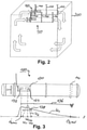
- FIG 2 shows schematically in a perspective view two air treatment systems 100 arranged in a closed room 200 for cleaning room air, as for example in FIG figure 1 or 3 shown.
- the air treatment systems 100 are mounted on the ceiling of the room 200 with a plurality of fastening elements 140, which are designed as pipe suspensions. It is therefore intended to mount several air treatment systems 100 in one room in order to increase the air purification rate.
- the two air treatment systems 100 create air circulation in the room 200, which is indicated by the arrows in FIG 2 is indicated.
- the room air in the room 200 is correspondingly cyclically conveyed through the two air treatment systems 100 .
- the air treatment systems 100 are arranged with pipe hangers 140 in a ceiling area or in the upper third of the room 200 . With this arrangement and the cyclical circulation of the room air, permanent air purification and efficient air purification are provided without ozone entering the room, as described above.
- the room 200 has a volume of 37,500 m 3 .
- the air flow rate of the two fan units is 12,500m 3 /h. This means that the entire room air is cleaned every 1.5 hours or calculated on the day, the entire room air is cleaned 16 times a day.
- FIG 3 shows a schematic diagram with two schematic characteristic curves K1 and K2 and an air treatment system 100, such as in FIG figure 1 or 2 shown.
- the characteristic curve K1 describes an ozone concentration ([O 3 per m3] or ppm) in the conveyed room air along the support body length s, i.e. along a path, within the duct of the air treatment system 100.
- the air treatment system 100 has an air treatment unit 130 with an ozone lamp 132 and a UV lamp 134, such as previously to the figures 1 and 2 described.
- the ozone concentration forms a maximum within the tube, which is referred to as the maximum ozone concentration (O 3,max ).
- the maximum is formed approximately where the ozone lamp 132 is located within the tube 110, which generates the ozone. If the air continues to flow along the support body length s, the ozone concentration of the ozone generated within the tube steadily decreases, since the ozone reacts with the air and is thus gradually broken down. After some time or after a certain distance, the ozone concentration is reduced to the final ozone concentration O 3,end . This can be set, for example as 0.08ppm.
- the section of length 136 which is between the maximum ozone concentration and the final ozone concentration is referred to as the ozone section.
- This section of length occurs essentially a reaction of the ozone with the conveyed room air.
- the support body length s of the air treatment system 100 is at least long enough for the final ozone concentration O 3,end to be reached. In order to save pipe material, for example, the support body or pipe length s can also coincide with the point at which the final ozone concentration O 3,end is present. This is indicated by the dashed fastener 140 in FIG 3 illustrated.
- the tube is thus long enough for the ozone to be broken down, but at most short.
- the course of the characteristic curve K2 describes an ionization intensity with which the conveyed room air is ionized along the support body length s within the duct of the air treatment system 100 . This can also be understood as the irradiation rate or irradiance.
- the ionization intensity forms a maximum within the tube, which is referred to as the maximum irradiation intensity Int ,max .
- the maximum radiation intensity is formed approximately where the UV lamp 132 is arranged inside the tube 110 .
- the length section 138 which lies between a first ionization intensity Int,1 and a second ionization intensity Int,2 is referred to as the ionization section, since essentially the air is ionized or irradiated in this section. If the conveyed room air flows along the support body length s through the ionization section, the loads in the air are oxidized by the irradiation so that they are reduced.
- the two points Int,1 and Int,2 are therefore the points at which the irradiation with UV light begins and ends within the channel.
Landscapes
- Engineering & Computer Science (AREA)
- Health & Medical Sciences (AREA)
- Chemical & Material Sciences (AREA)
- Combustion & Propulsion (AREA)
- Mechanical Engineering (AREA)
- General Engineering & Computer Science (AREA)
- Epidemiology (AREA)
- Life Sciences & Earth Sciences (AREA)
- Animal Behavior & Ethology (AREA)
- General Health & Medical Sciences (AREA)
- Public Health (AREA)
- Veterinary Medicine (AREA)
- Disinfection, Sterilisation Or Deodorisation Of Air (AREA)
Applications Claiming Priority (1)
| Application Number | Priority Date | Filing Date | Title |
|---|---|---|---|
| DE102020123367.1A DE102020123367A1 (de) | 2020-09-08 | 2020-09-08 | Luftbehandlungssystem zum Reinigen von Raumluft |
Publications (1)
| Publication Number | Publication Date |
|---|---|
| EP3964760A1 true EP3964760A1 (fr) | 2022-03-09 |
Family
ID=77595402
Family Applications (1)
| Application Number | Title | Priority Date | Filing Date |
|---|---|---|---|
| EP21194288.3A Pending EP3964760A1 (fr) | 2020-09-08 | 2021-09-01 | Système de traitement de l'air permettant de nettoyer l'air ambiant |
Country Status (3)
| Country | Link |
|---|---|
| US (1) | US20220072181A1 (fr) |
| EP (1) | EP3964760A1 (fr) |
| DE (1) | DE102020123367A1 (fr) |
Cited By (1)
| Publication number | Priority date | Publication date | Assignee | Title |
|---|---|---|---|---|
| IT202200022005A1 (it) * | 2022-10-25 | 2024-04-25 | Klimagiel S R L | “apparato di sanificazione per un impianto di distribuzione di un fluido, preferibilmente un impianto aerazione, ed impianto di aerazione” |
Citations (3)
| Publication number | Priority date | Publication date | Assignee | Title |
|---|---|---|---|---|
| DE102007037440A1 (de) | 2007-08-08 | 2009-02-12 | Meltem Wärmerückgewinnung GmbH & Co. KG | Luftreinigungsvorrichtung mit O3-Neutralisierer und Luftreinigungsverfahren |
| KR20100125601A (ko) * | 2009-05-21 | 2010-12-01 | (주)오맥스 | 공기 살균기 |
| US8048370B1 (en) * | 1997-11-21 | 2011-11-01 | Barnes Ronald L | Germicidal generator of ozone and ozonites |
Family Cites Families (4)
| Publication number | Priority date | Publication date | Assignee | Title |
|---|---|---|---|---|
| US2359021A (en) * | 1941-03-11 | 1944-09-26 | Campbell Horatio Guy | Combined lighting and air conditioning system |
| FR2316534A1 (fr) * | 1975-07-01 | 1977-01-28 | Sommer Horst | Agencement d'ecran directeur pour un emetteur de rayons ultraviolets en forme de barreau |
| JPH0687890B2 (ja) * | 1988-02-29 | 1994-11-09 | 東海興業株式会社 | 殺菌・脱臭装置 |
| US8388900B2 (en) * | 2007-11-21 | 2013-03-05 | Primaira, Llc | Apparatus and method for treating impurities in air and materials |
-
2020
- 2020-09-08 DE DE102020123367.1A patent/DE102020123367A1/de active Pending
-
2021
- 2021-09-01 EP EP21194288.3A patent/EP3964760A1/fr active Pending
- 2021-09-08 US US17/468,902 patent/US20220072181A1/en not_active Abandoned
Patent Citations (3)
| Publication number | Priority date | Publication date | Assignee | Title |
|---|---|---|---|---|
| US8048370B1 (en) * | 1997-11-21 | 2011-11-01 | Barnes Ronald L | Germicidal generator of ozone and ozonites |
| DE102007037440A1 (de) | 2007-08-08 | 2009-02-12 | Meltem Wärmerückgewinnung GmbH & Co. KG | Luftreinigungsvorrichtung mit O3-Neutralisierer und Luftreinigungsverfahren |
| KR20100125601A (ko) * | 2009-05-21 | 2010-12-01 | (주)오맥스 | 공기 살균기 |
Cited By (1)
| Publication number | Priority date | Publication date | Assignee | Title |
|---|---|---|---|---|
| IT202200022005A1 (it) * | 2022-10-25 | 2024-04-25 | Klimagiel S R L | “apparato di sanificazione per un impianto di distribuzione di un fluido, preferibilmente un impianto aerazione, ed impianto di aerazione” |
Also Published As
| Publication number | Publication date |
|---|---|
| DE102020123367A1 (de) | 2022-03-10 |
| US20220072181A1 (en) | 2022-03-10 |
Similar Documents
| Publication | Publication Date | Title |
|---|---|---|
| EP2025351B1 (fr) | Dispositif de purification d'air doté d'un neutraliseur d'O3 et procédé de purification d'air | |
| DE60304490T2 (de) | Methode und vorrichtung für die reinigung von luft | |
| EP3120084B1 (fr) | Appareil de conditionnement d'air océanique | |
| WO2006042740A2 (fr) | Dispositif et procede de sterilisation d'air ambiant | |
| DE102005029148A1 (de) | Vorrichtung zur Luftaufbereitung sowie Oberflächenbehandlungsanlage mit derselben | |
| EP0707178A2 (fr) | Méthode et dispositif pour le traitement d'air | |
| DE19513943A1 (de) | Verfahren und Vorrichtung zur Verbesserung der Raumluftqualität | |
| WO2005018692A1 (fr) | Dispositif de degermination d'un flux d'air a l'aide de lumiere uv | |
| DE202014104576U1 (de) | Lüftungsvorrichtung zur Lüftung eines Innenraumes einer Stallung | |
| EP2200760B1 (fr) | Dispositif et procédé pour nettoyer des espaces fermés | |
| EP3964760A1 (fr) | Système de traitement de l'air permettant de nettoyer l'air ambiant | |
| DE202006020800U1 (de) | Luftdesinfektionsvorrichtung | |
| DE202020106999U1 (de) | Modulares System zur Raumluftdesinfektion bzw. Entkeimung von Luft durch Behandlung mit ultravioletter Strahlung | |
| EP1541179A1 (fr) | Dispositif de stérilisation | |
| DE102021115065A1 (de) | Vorrichtung zur Luftreinigung, sowie ein Verfahren hierzu und deren Verwendung | |
| DE60037773T2 (de) | Vorrichtung und Verfahren zum Sterilisieren von Luft | |
| DE202018002599U1 (de) | Autoklimaanlage mit automatisierter Desinfektionsvorrichtung | |
| DE202021101555U1 (de) | Vorrichtung zur Filtration von Luft | |
| CH555679A (fr) | ||
| EP4171667B1 (fr) | Traitement de gaz | |
| DE202020105495U1 (de) | Luftreinigungsvorrichtung und Verwendung einer solchen | |
| DE102021105374A1 (de) | Luftaufbereitungsapparat | |
| AT10141U1 (de) | Klimagerät und verfahren zum aufbereiten von luft | |
| EP4082585B1 (fr) | Dispositif de nettoyage | |
| EP4000656A2 (fr) | Dispositif et procédé de réduction de la charge en substances nocives dans un gaz |
Legal Events
| Date | Code | Title | Description |
|---|---|---|---|
| PUAI | Public reference made under article 153(3) epc to a published international application that has entered the european phase |
Free format text: ORIGINAL CODE: 0009012 |
|
| STAA | Information on the status of an ep patent application or granted ep patent |
Free format text: STATUS: THE APPLICATION HAS BEEN PUBLISHED |
|
| AK | Designated contracting states |
Kind code of ref document: A1 Designated state(s): AL AT BE BG CH CY CZ DE DK EE ES FI FR GB GR HR HU IE IS IT LI LT LU LV MC MK MT NL NO PL PT RO RS SE SI SK SM TR |
|
| STAA | Information on the status of an ep patent application or granted ep patent |
Free format text: STATUS: REQUEST FOR EXAMINATION WAS MADE |
|
| 17P | Request for examination filed |
Effective date: 20220909 |
|
| RBV | Designated contracting states (corrected) |
Designated state(s): AL AT BE BG CH CY CZ DE DK EE ES FI FR GB GR HR HU IE IS IT LI LT LU LV MC MK MT NL NO PL PT RO RS SE SI SK SM TR |
|
| STAA | Information on the status of an ep patent application or granted ep patent |
Free format text: STATUS: EXAMINATION IS IN PROGRESS |
|
| 17Q | First examination report despatched |
Effective date: 20240604 |