EP4172076B1 - Système de transport comprenant des éléments de transport pliants - Google Patents
Système de transport comprenant des éléments de transport pliants Download PDFInfo
- Publication number
- EP4172076B1 EP4172076B1 EP21732990.3A EP21732990A EP4172076B1 EP 4172076 B1 EP4172076 B1 EP 4172076B1 EP 21732990 A EP21732990 A EP 21732990A EP 4172076 B1 EP4172076 B1 EP 4172076B1
- Authority
- EP
- European Patent Office
- Prior art keywords
- conveying
- carrier
- conveying belt
- folded
- receiving cavity
- Prior art date
- Legal status (The legal status is an assumption and is not a legal conclusion. Google has not performed a legal analysis and makes no representation as to the accuracy of the status listed.)
- Active
Links
Images





Classifications
-
- B—PERFORMING OPERATIONS; TRANSPORTING
- B65—CONVEYING; PACKING; STORING; HANDLING THIN OR FILAMENTARY MATERIAL
- B65G—TRANSPORT OR STORAGE DEVICES, e.g. CONVEYORS FOR LOADING OR TIPPING, SHOP CONVEYOR SYSTEMS OR PNEUMATIC TUBE CONVEYORS
- B65G15/00—Conveyors having endless load-conveying surfaces, i.e. belts and like continuous members, to which tractive effort is transmitted by means other than endless driving elements of similar configuration
- B65G15/30—Belts or like endless load-carriers
- B65G15/32—Belts or like endless load-carriers made of rubber or plastics
- B65G15/42—Belts or like endless load-carriers made of rubber or plastics having ribs, ridges, or other surface projections
-
- B—PERFORMING OPERATIONS; TRANSPORTING
- B65—CONVEYING; PACKING; STORING; HANDLING THIN OR FILAMENTARY MATERIAL
- B65G—TRANSPORT OR STORAGE DEVICES, e.g. CONVEYORS FOR LOADING OR TIPPING, SHOP CONVEYOR SYSTEMS OR PNEUMATIC TUBE CONVEYORS
- B65G17/00—Conveyors having an endless traction element, e.g. a chain, transmitting movement to a continuous or substantially-continuous load-carrying surface or to a series of individual load-carriers; Endless-chain conveyors in which the chains form the load-carrying surface
- B65G17/06—Conveyors having an endless traction element, e.g. a chain, transmitting movement to a continuous or substantially-continuous load-carrying surface or to a series of individual load-carriers; Endless-chain conveyors in which the chains form the load-carrying surface having a load-carrying surface formed by a series of interconnected, e.g. longitudinal, links, plates, or platforms
- B65G17/08—Conveyors having an endless traction element, e.g. a chain, transmitting movement to a continuous or substantially-continuous load-carrying surface or to a series of individual load-carriers; Endless-chain conveyors in which the chains form the load-carrying surface having a load-carrying surface formed by a series of interconnected, e.g. longitudinal, links, plates, or platforms the surface being formed by the traction element
-
- B—PERFORMING OPERATIONS; TRANSPORTING
- B65—CONVEYING; PACKING; STORING; HANDLING THIN OR FILAMENTARY MATERIAL
- B65G—TRANSPORT OR STORAGE DEVICES, e.g. CONVEYORS FOR LOADING OR TIPPING, SHOP CONVEYOR SYSTEMS OR PNEUMATIC TUBE CONVEYORS
- B65G17/00—Conveyors having an endless traction element, e.g. a chain, transmitting movement to a continuous or substantially-continuous load-carrying surface or to a series of individual load-carriers; Endless-chain conveyors in which the chains form the load-carrying surface
- B65G17/16—Conveyors having an endless traction element, e.g. a chain, transmitting movement to a continuous or substantially-continuous load-carrying surface or to a series of individual load-carriers; Endless-chain conveyors in which the chains form the load-carrying surface comprising individual load-carriers which are pivotally mounted, e.g. for free-swinging movement
- B65G17/18—Conveyors having an endless traction element, e.g. a chain, transmitting movement to a continuous or substantially-continuous load-carrying surface or to a series of individual load-carriers; Endless-chain conveyors in which the chains form the load-carrying surface comprising individual load-carriers which are pivotally mounted, e.g. for free-swinging movement and move in contact with a guiding surface
Definitions
- the present invention relates to a conveying system for conveying goods along a conveying direction to a discharge point, comprising:
- the present invention relates to such a conveying system for the food-processing industry, for conveying foodstuffs, such as for example fish or chicken.
- foodstuffs are typically tacky, sticky products.
- Such conveying systems are used to displace goods in various applications in the food-processing industry.
- weighing and/or sorting installations may be mentioned which typically require a supply of separate goods in order to be able to function.
- products are typically taken to the desired height and are then brought up to speed via conveying belts in order to weigh these products and/or sort them according to certain criteria.
- a minimum distance between the goods is necessary in order to make individual weighing possible. Furthermore, a sorting installation also requires a minimum intermediate distance. In order to make a weighing and/or sorting installation work as efficiently as possible, a supply installation (conveying system) is consequently required. This supply installation takes the goods one by one to the weighing and sorting installation.
- the positioning accuracy with which the goods are delivered to, for example, a weighing and/or sorting installation determines the capacity of the installation. If the difference in intermediate distance is considerable, the supply velocity will have to be lowered until the weighing and/or sorting installation is able to process all products. This may cause a great difference between the effective capacity and the maximum achievable capacity of the installation.
- the present invention relates to applications wherein conveying belts are provided with so-called carriers. These carriers are able to convey the separated product upwards without loss of separation. These carriers may also be used with horizontal conveying systems, in which case they only ensure that separated products do not touch each other.
- a subsequent device typically having a subsequent conveying belt
- a falling movement typically occurs, as a result of which the product drops in height and loses positioning accuracy. After all, it is not always possible to predict how the product will be entrained by the subsequent conveying belt after this falling movement.
- the carrier has as many drawbacks as advantages.
- the ideal conveying belt (optionally horizontal or ascending) only has carriers where they are required.
- the carriers are therefore provided in a conveying path for conveying the goods, but these carriers typically disappear before the product is discharged to a subsequent device.
- the carriers disappear before the discharge point in order to limit the drop height.
- the conveying belt then does not have any carriers at the location of the discharge point. This limits the drop in height and the product can be transferred without any significant falling movement.
- the height of the carriers is always limited in order to allow the conveying belt to travel through a bend at the location of the discharge point without the folded-down carriers hitting a subsequent device in which the goods are carried away.
- the goods which can be transported by means of such a conveying system are typically limited in size and in weight.
- GB 2 515 775 A describes a conveying system comprising folding carriers in which the folding carriers on top of the conveying belt fold down but part of them continues to protrude with respect to the conveying belt in the bend at the location of the supply point.
- the height of this carrier should be chosen as a compromise to the intermediate distance which this protruding carrier requires with respect to the device to which the goods are discharged.
- EP 1 826 159 A1 describes a conveying system in which the modules of the modular conveying belt (linked belt) are raised to form carriers. In order to do this, the belt has to be of sufficient length. As the conveying belt itself is raised locally, the height of the carrier which can be achieved thereby is thus limited to approximately one module of the conveying belt. Otherwise, a belt which is made too long causes several problems.
- EP 1 064 210 B1 describes a conveyor system comprising the features of the preamble of claim 1.
- This object of the invention is achieved by providing a conveying system for conveying goods along a conveying direction to a discharge point, comprising:
- each receiving cavity is provided with a length greater than a said intermediate distance, viewed in the conveying direction. Because this receiving cavity is free from conveying modules and pins, it is possible to accommodate a carrier in the folded-down position therein. As the receiving cavity is longer than said intermediate distance, this carrier may have a height greater than this intermediate distance. In addition, due to the fact that, in the folded-down position, this carrier can extend entirely within the closed path of the conveying belt, due to folding down these carriers at the location of the discharge point between the turning wheels at this discharge point, it is possible to ensure that the carrier will not protrude with respect to this conveying belt when the conveying belt follows a bend around these turning wheels.
- the conveying belt can still freely follow a bend around the turning wheels, as the conveying belt adjoining the lateral sides of the receiving cavity is designed to be continuous. On each lateral side of the receiving cavity, the corresponding continuous part of the conveying belt can be passed along the closed path over the corresponding turning wheel.
- the carrier can thus be designed to be higher than is the case with the prior art, as a result of which a larger variety of goods can be conveyed by means of such a conveying device.
- part modules and part pins may be provided here which are shorter than the conveying modules and pins in the other part of the conveying belt.
- carriers of different corresponding widths may be configured for this purpose. In this case, these carriers may be adapted to cover as large a width as possible of these conveying belts.
- conveying belts of different widths may be constructed using the same carriers, in which case the composite carriers together cover as large a width as possible of these conveying belts.
- each carrier of a conveying system preferably comprises a guide element.
- the conveying system furthermore preferably comprises a guide system for guiding the guide element in order to drive the pivoting movement of the carrier in such a way that, when driving the conveying belt along the closed path, in a conveying path of the closed path, the carrier remains in its folded-up position in order to convey the goods and the carrier is moved to its folded-down position at the location of the discharge point.
- Such a guide element may be designed to be a single piece with the rest of the carrier or may be designed as a separate element with which the carrier is provided.
- each carrier comprises a support element to support the carrier in the conveying path by means of the guide system on a support side of the corresponding receiving cavity opposite the front side of the receiving cavity.
- such a carrier is able to transmit larger forces.
- an even wider variety of goods can be conveyed.
- the turning wheels between which each carrier extends in the folded-down position at the location of the discharge point, will be arranged so as to be rotatable about an axle.
- this axle forms part of the guide system.
- the axle is provided in order thereby to guide the guide element at the location of the discharge point, when the carrier extends between these turning wheels.
- Each carrier will comprise a front wall which is provided in order to be upright in the folded-up position of the carrier with respect to the conveying belt on the front side of the receiving cavity.
- this front wall in the folded-up position of the carrier, this front wall then preferably extends at an angle of between 45° and 90° with respect to the conveying belt and still more preferably at an angle of approximately 90°.
- the carriers may be of substantially plate-shaped design. In the simplest embodiment, this carrier will leave the receiving cavity substantially free in the folded-up position. In order to prevent goods from falling into this receiving cavity, for example carrying straps may be provided below the conveying belt which cover this receiving cavity.
- a carrier will also comprise one or more additional covering walls in addition to the front wall in order to cover the corresponding receiving cavity in the folded-up position of the carrier.
- a carrier with such a front wall and one or more covering walls is preferably of a hollow design in order to make it as lightweight as possible. However, it is also possible to make such a carrier solid.
- each carrier may comprise side walls as covering walls on both its lateral sides
- at least one of these side is then preferably designed as a said guide element.
- This side wall then has a double function, on the one hand for covering the receiving cavity and on the other hand for driving the pivoting movement of the carrier.
- both side walls are designed as such a guide element.
- each side wall which is designed as a guide element is provided with a recess along its bottom edge for accommodating the axle which forms part of the guide system.
- the side wall may be designed to be hook-shaped between the support element and the recess in order to hook the side wall over the axle.
- a conveying system preferably also comprises a release element which is disposed at the location of the axle to engage with each carrier in order to release the carrier from the axle in order to ensure that the carrier does not get stuck to the axle in an undesirable manner which would prevent the conveying belt from being driven further.
- a carrier On its side opposite said front wall, a carrier preferably also comprises a rear wall as covering wall.
- this rear wall is preferably of a concave design. By making it concave, this rear wall may, in the folded-up position of the carrier, adjoin the corresponding edge of the receiving cavity, without this rear wall becoming stuck to this edge during the pivoting movement of the carrier. By means of such a rear wall, it is therefore possible to cover the receiving cavity to the maximum degree.
- this support element preferably forms a projection at the bottom of the rear wall.
- this support element then preferably extends at the bottom of this rear wall along the entire edge.
- each carrier preferably also comprises a top wall as a covering wall which connects the front wall and the rear wall.
- this top wall may extend virtually parallel to the conveying belt in the folded-up position of the carrier.
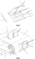
- the illustrated conveying systems (1) are configured for conveying foodstuffs, such as fish or chicken, to a discharge point (X) along a conveying direction (A).
- these conveying systems (1) are configured to transport these goods upwards to a further device (not shown), which is arranged at the location of the discharge point (X) and adjoining the illustrated conveying systems (1).
- a further device not shown
- conveying systems (1) in which the goods are moved substantially horizontally.
- the illustrated conveying systems (1) can easily be modified in a known manner.
- the conveying systems (1) in each case comprise a conveying belt (2) which is configured as a linked belt and is to this end provided with conveying modules (3) which are coupled together by means of pins (4) to form the conveying belt (2).
- the pins (4) are, viewed transversely to the conveying direction (A), arranged at an intermediate distance (t) apart. Constructing a conveying belt (2) by means of such conveying modules (3) and pins (4) is well-known. In order to keep the figures simple, these conveying modules (3) and pins (4) have only been shown in Figs. 9 and 10 .
- the endless conveying belt (2) is in each case drivable about turning wheels (7, 8) along a closed path. Further guide wheels (25) concomitantly determine this closed path.
- the top turning wheels (7) are in each case fitted so as to be rotatable about a driven axle (9).
- the bottom turning wheels (8) are arranged so as to be freely rotatable about an axle. Alternatively, it is also possible, conversely, to drive the bottom turning wheels and to arrange the top turning wheels so as to be freely rotatably.
- the guide wheels (25) are arranged so as to be freely rotatable about an axle.
- the conveying systems (1) are in each case provided with receiving cavities (6) at a regular intermediate distance apart, in which the conveying belt (2) is free from conveying modules (3) and from pins (4) over the length (1) of more than one said intermediate distance (t).
- the conveying belt (2) is designed to be continuous, for example by means of part modules (3') and part pins (4'), as is illustrated in Fig. 9 Alternatively, it is for example possible to provide a portion of a belt or chain for this purpose, in order to complete the conveying belt (2) between the conveying modules (3) and pins (4).
- a carrier (5) is in each case hingeably attached to a pin (4) which is arranged adjacent to this receiving cavity (6).
- the carriers (5) in each case have a height (h) greater than a said intermediate distance (t).
- Each carrier (5) is at least hingeable between a folded-down position, in which this carrier (5) is accommodated in the receiving cavity (6), and a folded-up position, in which this carrier (5) is upright with respect to the conveying belt (2) in order to entrain the goods when conveying these goods.
- the carriers (5) which are arranged on the top side of the conveying belt (2) are in each case in the folded-up position and the carriers (5) which are arranged at the location of the discharge point (X) are in each case in the folded-down position.
- the carriers (5) in each case extend entirely within the closed path of the conveying belt (2), between the top turning wheels (7), as can be seen in Figs. 1-2 , 4 , 6 , 8 and 25 .
- these carriers (5) are in each case also hingeable beyond these said positions.
- the carriers (5) which, in the figures, hang from the underside of the conveying belt (2), hang down on account of the force of gravity and they may in this case be tilted beyond the folded-up position. In principle, these carriers (5) may also be tilted in the opposite direction to beyond the folded-down position. During normal operation of the illustrated conveying system (1), these will however not tilt beyond this folded-down position, as will also be explained below.
- the illustrated conveying systems comprise a guide system (9, 10) for guiding a guide element (14) of the carrier (5).
- the drive of this pivoting movement can be seen most clearly in Figs. 1 and 2 .
- the guide system (9, 10) in each case comprises guide rails (10) which are arranged within the closed path under the top part of the conveying belt (2).
- the carriers (5) hang freely downwards below the conveying belt (2) on account of their weight, and are tilted beyond the folded-up position.
- the carriers (5) tilt to their folded-up position when the conveying belt (2) is passed around the bottom turning wheels (8).
- guide rails and/or guide strips (10) keep the carriers (5) in their folded-up position due to the fact that their guide element (14) is passed on top of these guide rails and/or guide strips (10).
- a downward piece (11) is provided which ensures that the carriers (5) start to tilt to their folded-down position.
- the carriers (5) are of the simplest design. These are existing carriers (5) which are normally fixedly arranged in conveying systems without being able to fold down. This first embodiment of a conveying system (1) can therefore be carried out in a relatively simple and inexpensive manner. In existing conveying systems, these carriers (5) are fixed with two pins. Now, these carriers (5) are only fitted using one of the two pins (5) provided at the front of a flange (14) which is provided below the carrier (5) and which also serves as said guide element.
- each of these carriers (5) is thus pulled forward at the front.
- these carriers (5) are arranged so as to be free.
- this carrier (5) can now hinge downwards at the locations where no carrier (5) is required in the conveying system (1).
- this carrier (5) cannot transmit any pulling power at this location in the conveying belt (2).
- a piece of continuous belt or chain will be provided next to or between these carriers (5) which can absorb the pulling power. If a few modules are omitted behind this carrier (5) to form the receiving cavity (6), there is space to allow this high carrier (5) to fold down into the conveying belt (2).
- the carrier (5) is made longer than said intermediate distance (t).
- This carrier (5) has a height which is necessary in order to convey the product in the desired manner or to raise it.
- the carrier (5) has a front wall (13) which is provided in order to be upright in the folded-up position with respect to the conveying belt (2) on the front side of the receiving cavity (6), side walls (14) on its two lateral sides, a rear wall (19) and a top wall (21).
- the side walls (14), rear wall (19) and top wall (21) serve as covering walls (14, 19, 21).
- the shape of the carrier (5) with several covering walls (14, 19, 21) prevents an opening in the conveying belt (2) being created downstream of the carrier (5).
- This carrier (5) is therefore sufficiently long to cover the receiving cavity (6), which is necessary for folding-in, in the folded-up position.
- the space where product can be deposited is limited to a specific zone behind the carrier (5), as a result of which this conveying system may also be used without an inclined part in the conveying belt (2) being provided.
- a space having a length which is three times the intermediate distance (t) is in each case provided downstream of the carrier (5) for depositing a product.
- the length of the carrier (5) is in this case (not obligatory) the equivalent of 3 intermediate distances (t).
- the carrier (5) is provided with a support element (16) in order to support the carrier (5) in the conveying path on a support side of the receiving cavity (6) opposite the front side of the receiving cavity (6) by means of the guide rails and/or guide strips (10).
- the geometry is specifically adapted to the diameter of the driven turning wheels (7).
- the side walls (14) of the carrier (5) are designed as guide element (14).
- the turning wheels (7) are arranged so as to be rotatable about the drive axle (9).
- This drive axle (9) forms part of the guide system (9, 10).
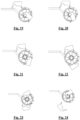
- the rear side of the carrier (5) drops to behind the axle (9) of the drive in order to be able to fold down to a sufficient degree, so that this carrier (5) can extend entirely within the closed path of the conveying belt (2) up to the edge (22) between the front wall (13) and the top wall (21).
- the bottom edge (15) of the side walls (14) is provided with a recess (17) for accommodating the axle (9) therein.
- Each side wall (14) is of a hook-shaped design between the support element (16) and the recess (17) in order to hook the side wall (14) over the axle (9).
- the rear wall (19) is of a concave design and the support element (16) forms a projection below the rear wall (19), so that an indentation (20) is formed between the rear wall (19) and the support element (16).
- the carrier (5) may, in its folded-up position, extend along virtually the entire length of the receiving cavity (6), without the support element (16) or the rear wall (19) getting stuck on the edge of the receiving cavity (6) when the carrier (5) folds down.
- a release element (12) is furthermore provided to engage with the carrier (5) in order to release the carrier (5) from the axle (9).
- This release element (12) is provided to ensure that the carrier (5) folds up at the correct moment. This prevents the carrier (5) from getting stuck around the axle (9) on the return.
- lateral guides (24) are arranged on the lateral sides, as is illustrated in Fig. 10 .
- these lateral guides (24) extend over the lateral sides of the conveying belt (2) and in this case also largely cover the continuous pieces of the conveying belt on the lateral sides of the receiving cavities (6).
- the carriers (5) together extend virtually across the entire width of the conveying belt (2) between these lateral guides (24).
- each case two carriers (5) are arranged adjoining each other for each receiving cavity (6) to this end.
Landscapes
- Engineering & Computer Science (AREA)
- Mechanical Engineering (AREA)
- Structure Of Belt Conveyors (AREA)
- Chain Conveyers (AREA)
Claims (12)
- Système de transport (1) pour transporter des marchandises le long d'une direction de transport (A) jusqu'à un point de décharge (X), comprenant :- une courroie transporteuse (2), comprenant des modules de transport (3) et des broches (4), qui s'étendent transversalement à la direction de transport (A), dans laquelle les broches (4) sont disposées à une distance intermédiaire (t) afin d'accoupler les modules de transport (3) de manière à former la courroie transporteuse (2) ;- des roues tournantes (7, 8) autour desquelles la courroie transporteuse (2) peut être entraînée le long d'un trajet fermé ;- des cavités de réception (6), dans lesquelles la courroie transporteuse (2) est exempte desdits modules de transport (3), la courroie transporteuse (2) étant conçue pour être continue au voisinage des côtés latéraux des cavités de réception (6) ; et- des éléments de support (5), chaque élément de support (5) étant attaché de manière articulée à une broche (4), qui est disposée sur un côté avant d'une cavité de réception (6), entre une position repliée, dans laquelle cet élément de support (5) est logé dans cette cavité de réception correspondante (6), et une position dépliée, dans laquelle cet élément de support (5) est vertical relativement à la courroie transporteuse (2) afin d'entraîner les marchandises lors du transport de ces marchandises ;caractérisé en ce que chaque élément de support (5) a une hauteur (h) supérieure à ladite distance intermédiaire (t), en ce que chaque cavité de réception (6), vue dans la direction de transport (A), est exempte de modules de transport (3) et de broches (4) le long d'une longueur (1) supérieure à ladite distance intermédiaire (t),et en ce que chaque élément de support (5) s'étend entièrement à l'intérieur du trajet fermé de la courroie transporteuse (2), entre lesdites roues tournantes (7), à l'emplacement du point de décharge (X) et dans la position repliée.
- Système de transport (1) selon la revendication 1, caractérisé en ce que chaque élément de support (5) comprend un élément de guidage (14), en ce que le système de transport (1) comprend un système de guidage (9, 10) pour guider l'élément de guidage (14) afin d'entraîner le mouvement de pivotement de l'élément de support (5) de telle sorte que, lors de l'entraînement de la courroie transporteuse (2) le long du trajet fermé, dans un trajet de transport du trajet fermé, l'élément de support (5) reste dans sa position dépliée pour transporter les marchandises et l'élément de support (5) est déplacé dans sa position repliée à l'emplacement du point de décharge (X) .
- Système de transport (1) selon la revendication 2, caractérisé en ce que chaque élément de support (5) comprend un élément de soutien (16) pour soutenir l'élément de support (5) dans le trajet de transport au moyen du système de guidage (9, 10) sur un côté de soutien de la cavité de réception correspondante (6) opposé au côté avant de la cavité de réception (6).
- Système de transport (1) selon la revendication 2 ou 3, caractérisé en ce que lesdites roues tournantes (7) sont disposées de manière à pouvoir tourner autour d'un essieu (9) à l'emplacement du point de décharge (X), entre lesquelles s'étend chaque élément de support (5) en position repliée à l'emplacement de ce point de décharge (X), et en ce que cet essieu (9) fait partie du système de guidage (9, 10).
- Système de transport (1) selon l'une des revendications précédentes, caractérisé en ce que chaque élément de support (5) comprend une paroi avant (13) qui est prévue pour être verticale dans la position dépliée de l'élément de support (5) par rapport à la courroie transporteuse (2) sur le côté avant de la cavité de réception (6), et une ou plusieurs parois de recouvrement supplémentaires (14, 19, 21) pour recouvrir la cavité de réception correspondante (6) dans la position dépliée de l'élément de support (5).
- Système de transport (1) selon les revendications 2 et 5, caractérisé en ce que chaque élément de support (5) comprend des parois latérales (14) en tant que parois de recouvrement (14, 19, 21) sur ses deux côtés latéraux, dans lequel au moins une de ces parois latérales (14) est conçue comme un élément de guidage (14).
- Système de transport (1) selon les revendications 4 et 6, caractérisé en ce que la paroi latérale (14) conçue comme un élément de guidage (14) est pourvue d'un renfoncement (17) le long de son bord inférieur (15) pour y loger l'essieu (9).
- Système de transport (1) selon les revendications 3 et 7, caractérisé en ce que la paroi latérale (14) est conçue pour être en forme de crochet entre l'élément de soutien (16) et le renfoncement (17) afin d'accrocher la paroi latérale (14) sur l'essieu (9).
- Système de transport (1) selon la revendication 7 ou 8, caractérisé en ce que le système de transport (1) comprend un élément de libération (12) qui est disposé à l'emplacement de l'essieu (9) pour entrer en prise avec chaque élément de support (5) afin de libérer l'élément de support (5) de l'essieu (9).
- Système de transport (1) selon l'une des revendications 5 à 9, caractérisé en ce que chaque élément de support (5) comprend une paroi arrière (19) de forme concave en tant que paroi de recouvrement (14, 19, 21) sur son côté opposé à la paroi avant (13).
- Système de transport (1) selon les revendications 3 et 9, caractérisé en ce que l'élément de soutien (16) forme une saillie au bas de la paroi arrière (19).
- Système de transport (1) selon la revendication 10 ou 11, caractérisé en ce que chaque élément de support (5) comprend une paroi supérieure (21) en tant que paroi de recouvrement (14, 19, 21) qui relie la paroi avant (13) et la paroi arrière (19).
Applications Claiming Priority (2)
| Application Number | Priority Date | Filing Date | Title |
|---|---|---|---|
| BE20205468A BE1028434B1 (nl) | 2020-06-25 | 2020-06-25 | Transportsysteem met opklapbare meenemers |
| PCT/IB2021/055243 WO2021260489A1 (fr) | 2020-06-25 | 2021-06-15 | Système de transport comprenant des éléments de transport pliants |
Publications (3)
| Publication Number | Publication Date |
|---|---|
| EP4172076A1 EP4172076A1 (fr) | 2023-05-03 |
| EP4172076C0 EP4172076C0 (fr) | 2024-07-31 |
| EP4172076B1 true EP4172076B1 (fr) | 2024-07-31 |
Family
ID=71465025
Family Applications (1)
| Application Number | Title | Priority Date | Filing Date |
|---|---|---|---|
| EP21732990.3A Active EP4172076B1 (fr) | 2020-06-25 | 2021-06-15 | Système de transport comprenant des éléments de transport pliants |
Country Status (4)
| Country | Link |
|---|---|
| US (1) | US12012286B2 (fr) |
| EP (1) | EP4172076B1 (fr) |
| BE (1) | BE1028434B1 (fr) |
| WO (1) | WO2021260489A1 (fr) |
Citations (1)
| Publication number | Priority date | Publication date | Assignee | Title |
|---|---|---|---|---|
| EP1064210B1 (fr) * | 1998-03-20 | 2003-01-08 | Ammeraal Beltech B.V. | Systeme de transporteur destine a transporter et a accumuler des objets |
Family Cites Families (13)
| Publication number | Priority date | Publication date | Assignee | Title |
|---|---|---|---|---|
| US3534848A (en) * | 1968-06-19 | 1970-10-20 | Amsted Ind Inc | Fold down lug for chains |
| DE8915286U1 (de) * | 1989-12-30 | 1990-03-29 | NIKO Nahrungsmittel-Maschinen GmbH & Co KG, 41334 Nettetal | Steilförderer für Gemüse, Obst u.dgl. |
| US7537105B2 (en) * | 2005-08-15 | 2009-05-26 | Laitram, L.L.C. | Apparatus and methods for controlling spacing of conveyed objects |
| NL1031219C2 (nl) | 2006-02-22 | 2007-09-03 | Ammeraal Beltech B V | Transportsysteem. |
| JP5345623B2 (ja) * | 2007-08-22 | 2013-11-20 | レイトラム リミテッド ライアビリティー カンパニー | 荷物間に間隔を設けるコンベヤと方法 |
| EP2523858B1 (fr) * | 2010-01-13 | 2022-03-23 | Laitram, LLC | Transporteur à bande de mesure à marche arrière |
| US8701871B2 (en) * | 2011-03-25 | 2014-04-22 | Laitram, L.L.C. | Belt conveyor with snagless retractable flights |
| DK177451B1 (en) * | 2011-09-12 | 2013-06-17 | Palle Stockholm Johansson | Flight conveyor |
| DK201370199A (en) * | 2013-01-15 | 2014-07-16 | Ammeraal Beltech Modular As | In-feed for product support conveyor |
| EP2945888B1 (fr) | 2013-01-15 | 2018-03-21 | Ammeraal Beltech Modular A/S | Maillon articulé |
| US8944236B2 (en) * | 2013-05-13 | 2015-02-03 | Laitram, L.L.C. | Method and conveyor for registering articles on a conveyor belt |
| GB2515775A (en) | 2013-07-03 | 2015-01-07 | Ammeraal Beltech Modular As | Conveyor and conveyor structure |
| US11117748B1 (en) * | 2020-12-28 | 2021-09-14 | Cleasby Llc | Gravitationally directed conveyor material cleat |
-
2020
- 2020-06-25 BE BE20205468A patent/BE1028434B1/nl active IP Right Grant
-
2021
- 2021-06-15 WO PCT/IB2021/055243 patent/WO2021260489A1/fr not_active Ceased
- 2021-06-15 EP EP21732990.3A patent/EP4172076B1/fr active Active
- 2021-06-15 US US18/011,825 patent/US12012286B2/en active Active
Patent Citations (1)
| Publication number | Priority date | Publication date | Assignee | Title |
|---|---|---|---|---|
| EP1064210B1 (fr) * | 1998-03-20 | 2003-01-08 | Ammeraal Beltech B.V. | Systeme de transporteur destine a transporter et a accumuler des objets |
Also Published As
| Publication number | Publication date |
|---|---|
| EP4172076C0 (fr) | 2024-07-31 |
| BE1028434B1 (nl) | 2022-01-31 |
| US12012286B2 (en) | 2024-06-18 |
| EP4172076A1 (fr) | 2023-05-03 |
| WO2021260489A1 (fr) | 2021-12-30 |
| US20230242346A1 (en) | 2023-08-03 |
| BE1028434A1 (nl) | 2022-01-26 |
Similar Documents
| Publication | Publication Date | Title |
|---|---|---|
| EP0189693B1 (fr) | Appareil automatique pour charger directement des biscuits doux | |
| EP2945888B1 (fr) | Maillon articulé | |
| US9126758B2 (en) | Arrangements for transferring articles | |
| US10577194B2 (en) | Sorting device with improved capacity | |
| US4627530A (en) | Elevating chain conveyor | |
| EP0784026A1 (fr) | Transporteur | |
| EP0142726B1 (fr) | Transporteur élévateur à chaîne | |
| EP3696122B1 (fr) | Trieuse à bande transversale | |
| FI102026B (fi) | Perunanistutuskoneen kuppikuljetin | |
| US12012286B2 (en) | Conveying system comprising folding carriers | |
| EP3170152B1 (fr) | Transport d'unités monétaires | |
| EP0608103B1 (fr) | Système de transport à poussoirs pour cartons en machines d'emballage | |
| US4799583A (en) | Automatic direct soft cookie loading apparatus | |
| EP0621851B1 (fr) | Installation de transport | |
| JP2589607B2 (ja) | 品物の計重・仕分装置 | |
| NL1007820C2 (nl) | Transportinrichting. | |
| JP2684503B2 (ja) | 物品の荷受方法及び装置 | |
| NL1019158C2 (nl) | Transportvoertuig, in het bijzonder voor het vervoeren van kippen, alsmede werkwijze voor het beladen van het transportvoertuig. | |
| JP2633112B2 (ja) | バケットコンベヤにおけるバケット | |
| NL2001708C2 (en) | A conveying device. | |
| NL8403060A (nl) | Inlijninrichting van flessen of dergelijke. | |
| WO2006040166A1 (fr) | Systeme de voie a debit reglable integrant un plateau | |
| JP2652496B2 (ja) | コンベヤ装置からの物品排出方法及び装置 | |
| WO1994018101A1 (fr) | Dispositif de transport de bagages | |
| JPH09124128A (ja) | 容器への物品投入装置 |
Legal Events
| Date | Code | Title | Description |
|---|---|---|---|
| STAA | Information on the status of an ep patent application or granted ep patent |
Free format text: STATUS: UNKNOWN |
|
| STAA | Information on the status of an ep patent application or granted ep patent |
Free format text: STATUS: THE INTERNATIONAL PUBLICATION HAS BEEN MADE |
|
| PUAI | Public reference made under article 153(3) epc to a published international application that has entered the european phase |
Free format text: ORIGINAL CODE: 0009012 |
|
| STAA | Information on the status of an ep patent application or granted ep patent |
Free format text: STATUS: REQUEST FOR EXAMINATION WAS MADE |
|
| 17P | Request for examination filed |
Effective date: 20221216 |
|
| AK | Designated contracting states |
Kind code of ref document: A1 Designated state(s): AL AT BE BG CH CY CZ DE DK EE ES FI FR GB GR HR HU IE IS IT LI LT LU LV MC MK MT NL NO PL PT RO RS SE SI SK SM TR |
|
| DAV | Request for validation of the european patent (deleted) | ||
| DAX | Request for extension of the european patent (deleted) | ||
| GRAP | Despatch of communication of intention to grant a patent |
Free format text: ORIGINAL CODE: EPIDOSNIGR1 |
|
| STAA | Information on the status of an ep patent application or granted ep patent |
Free format text: STATUS: GRANT OF PATENT IS INTENDED |
|
| INTG | Intention to grant announced |
Effective date: 20240228 |
|
| GRAS | Grant fee paid |
Free format text: ORIGINAL CODE: EPIDOSNIGR3 |
|
| GRAA | (expected) grant |
Free format text: ORIGINAL CODE: 0009210 |
|
| STAA | Information on the status of an ep patent application or granted ep patent |
Free format text: STATUS: THE PATENT HAS BEEN GRANTED |
|
| AK | Designated contracting states |
Kind code of ref document: B1 Designated state(s): AL AT BE BG CH CY CZ DE DK EE ES FI FR GB GR HR HU IE IS IT LI LT LU LV MC MK MT NL NO PL PT RO RS SE SI SK SM TR |
|
| REG | Reference to a national code |
Ref country code: CH Ref legal event code: EP Ref country code: GB Ref legal event code: FG4D |
|
| REG | Reference to a national code |
Ref country code: DE Ref legal event code: R096 Ref document number: 602021016495 Country of ref document: DE |
|
| REG | Reference to a national code |
Ref country code: IE Ref legal event code: FG4D |
|
| U01 | Request for unitary effect filed |
Effective date: 20240802 |
|
| U07 | Unitary effect registered |
Designated state(s): AT BE BG DE DK EE FI FR IT LT LU LV MT NL PT RO SE SI Effective date: 20240902 |
|
| PG25 | Lapsed in a contracting state [announced via postgrant information from national office to epo] |
Ref country code: NO Free format text: LAPSE BECAUSE OF FAILURE TO SUBMIT A TRANSLATION OF THE DESCRIPTION OR TO PAY THE FEE WITHIN THE PRESCRIBED TIME-LIMIT Effective date: 20241031 |
|
| PG25 | Lapsed in a contracting state [announced via postgrant information from national office to epo] |
Ref country code: PL Free format text: LAPSE BECAUSE OF FAILURE TO SUBMIT A TRANSLATION OF THE DESCRIPTION OR TO PAY THE FEE WITHIN THE PRESCRIBED TIME-LIMIT Effective date: 20240731 Ref country code: GR Free format text: LAPSE BECAUSE OF FAILURE TO SUBMIT A TRANSLATION OF THE DESCRIPTION OR TO PAY THE FEE WITHIN THE PRESCRIBED TIME-LIMIT Effective date: 20241101 |
|
| PG25 | Lapsed in a contracting state [announced via postgrant information from national office to epo] |
Ref country code: IS Free format text: LAPSE BECAUSE OF FAILURE TO SUBMIT A TRANSLATION OF THE DESCRIPTION OR TO PAY THE FEE WITHIN THE PRESCRIBED TIME-LIMIT Effective date: 20241130 |
|
| PG25 | Lapsed in a contracting state [announced via postgrant information from national office to epo] |
Ref country code: HR Free format text: LAPSE BECAUSE OF FAILURE TO SUBMIT A TRANSLATION OF THE DESCRIPTION OR TO PAY THE FEE WITHIN THE PRESCRIBED TIME-LIMIT Effective date: 20240731 |
|
| PG25 | Lapsed in a contracting state [announced via postgrant information from national office to epo] |
Ref country code: RS Free format text: LAPSE BECAUSE OF FAILURE TO SUBMIT A TRANSLATION OF THE DESCRIPTION OR TO PAY THE FEE WITHIN THE PRESCRIBED TIME-LIMIT Effective date: 20241031 Ref country code: ES Free format text: LAPSE BECAUSE OF FAILURE TO SUBMIT A TRANSLATION OF THE DESCRIPTION OR TO PAY THE FEE WITHIN THE PRESCRIBED TIME-LIMIT Effective date: 20240731 |
|
| PG25 | Lapsed in a contracting state [announced via postgrant information from national office to epo] |
Ref country code: RS Free format text: LAPSE BECAUSE OF FAILURE TO SUBMIT A TRANSLATION OF THE DESCRIPTION OR TO PAY THE FEE WITHIN THE PRESCRIBED TIME-LIMIT Effective date: 20241031 Ref country code: PL Free format text: LAPSE BECAUSE OF FAILURE TO SUBMIT A TRANSLATION OF THE DESCRIPTION OR TO PAY THE FEE WITHIN THE PRESCRIBED TIME-LIMIT Effective date: 20240731 Ref country code: NO Free format text: LAPSE BECAUSE OF FAILURE TO SUBMIT A TRANSLATION OF THE DESCRIPTION OR TO PAY THE FEE WITHIN THE PRESCRIBED TIME-LIMIT Effective date: 20241031 Ref country code: IS Free format text: LAPSE BECAUSE OF FAILURE TO SUBMIT A TRANSLATION OF THE DESCRIPTION OR TO PAY THE FEE WITHIN THE PRESCRIBED TIME-LIMIT Effective date: 20241130 Ref country code: HR Free format text: LAPSE BECAUSE OF FAILURE TO SUBMIT A TRANSLATION OF THE DESCRIPTION OR TO PAY THE FEE WITHIN THE PRESCRIBED TIME-LIMIT Effective date: 20240731 Ref country code: GR Free format text: LAPSE BECAUSE OF FAILURE TO SUBMIT A TRANSLATION OF THE DESCRIPTION OR TO PAY THE FEE WITHIN THE PRESCRIBED TIME-LIMIT Effective date: 20241101 Ref country code: ES Free format text: LAPSE BECAUSE OF FAILURE TO SUBMIT A TRANSLATION OF THE DESCRIPTION OR TO PAY THE FEE WITHIN THE PRESCRIBED TIME-LIMIT Effective date: 20240731 |
|
| PG25 | Lapsed in a contracting state [announced via postgrant information from national office to epo] |
Ref country code: SM Free format text: LAPSE BECAUSE OF FAILURE TO SUBMIT A TRANSLATION OF THE DESCRIPTION OR TO PAY THE FEE WITHIN THE PRESCRIBED TIME-LIMIT Effective date: 20240731 |
|
| PG25 | Lapsed in a contracting state [announced via postgrant information from national office to epo] |
Ref country code: CZ Free format text: LAPSE BECAUSE OF FAILURE TO SUBMIT A TRANSLATION OF THE DESCRIPTION OR TO PAY THE FEE WITHIN THE PRESCRIBED TIME-LIMIT Effective date: 20240731 |
|
| PG25 | Lapsed in a contracting state [announced via postgrant information from national office to epo] |
Ref country code: SK Free format text: LAPSE BECAUSE OF FAILURE TO SUBMIT A TRANSLATION OF THE DESCRIPTION OR TO PAY THE FEE WITHIN THE PRESCRIBED TIME-LIMIT Effective date: 20240731 |
|
| PLBE | No opposition filed within time limit |
Free format text: ORIGINAL CODE: 0009261 |
|
| STAA | Information on the status of an ep patent application or granted ep patent |
Free format text: STATUS: NO OPPOSITION FILED WITHIN TIME LIMIT |
|
| 26N | No opposition filed |
Effective date: 20250501 |
|
| U20 | Renewal fee for the european patent with unitary effect paid |
Year of fee payment: 5 Effective date: 20250627 |
|
| REG | Reference to a national code |
Ref country code: CH Ref legal event code: H13 Free format text: ST27 STATUS EVENT CODE: U-0-0-H10-H13 (AS PROVIDED BY THE NATIONAL OFFICE) Effective date: 20260127 |
|
| PG25 | Lapsed in a contracting state [announced via postgrant information from national office to epo] |
Ref country code: MC Free format text: LAPSE BECAUSE OF FAILURE TO SUBMIT A TRANSLATION OF THE DESCRIPTION OR TO PAY THE FEE WITHIN THE PRESCRIBED TIME-LIMIT Effective date: 20240731 |
|
| GBPC | Gb: european patent ceased through non-payment of renewal fee |
Effective date: 20250615 |
|
| PG25 | Lapsed in a contracting state [announced via postgrant information from national office to epo] |
Ref country code: GB Free format text: LAPSE BECAUSE OF NON-PAYMENT OF DUE FEES Effective date: 20250615 |
|
| PG25 | Lapsed in a contracting state [announced via postgrant information from national office to epo] |
Ref country code: IE Free format text: LAPSE BECAUSE OF NON-PAYMENT OF DUE FEES Effective date: 20250615 |
|
| PG25 | Lapsed in a contracting state [announced via postgrant information from national office to epo] |
Ref country code: CH Free format text: LAPSE BECAUSE OF NON-PAYMENT OF DUE FEES Effective date: 20250630 |