EP4173943B1 - Catamaran à propulsion à ailerons - Google Patents
Catamaran à propulsion à ailerons Download PDFInfo
- Publication number
- EP4173943B1 EP4173943B1 EP22203538.8A EP22203538A EP4173943B1 EP 4173943 B1 EP4173943 B1 EP 4173943B1 EP 22203538 A EP22203538 A EP 22203538A EP 4173943 B1 EP4173943 B1 EP 4173943B1
- Authority
- EP
- European Patent Office
- Prior art keywords
- drive
- catamaran
- fin
- drive fin
- wall areas
- Prior art date
- Legal status (The legal status is an assumption and is not a legal conclusion. Google has not performed a legal analysis and makes no representation as to the accuracy of the status listed.)
- Active
Links
Images



Classifications
-
- B—PERFORMING OPERATIONS; TRANSPORTING
- B63—SHIPS OR OTHER WATERBORNE VESSELS; RELATED EQUIPMENT
- B63H—MARINE PROPULSION OR STEERING
- B63H1/00—Propulsive elements directly acting on water
- B63H1/30—Propulsive elements directly acting on water of non-rotary type
- B63H1/32—Flaps, pistons, or the like, reciprocating in propulsive direction
-
- B—PERFORMING OPERATIONS; TRANSPORTING
- B63—SHIPS OR OTHER WATERBORNE VESSELS; RELATED EQUIPMENT
- B63H—MARINE PROPULSION OR STEERING
- B63H1/00—Propulsive elements directly acting on water
- B63H1/30—Propulsive elements directly acting on water of non-rotary type
- B63H1/37—Moving-wave propellers, i.e. wherein the propelling means comprise a flexible undulating structure
-
- B—PERFORMING OPERATIONS; TRANSPORTING
- B63—SHIPS OR OTHER WATERBORNE VESSELS; RELATED EQUIPMENT
- B63H—MARINE PROPULSION OR STEERING
- B63H16/00—Marine propulsion by muscle power
- B63H16/08—Other apparatus for converting muscle power into propulsive effort
- B63H16/20—Other apparatus for converting muscle power into propulsive effort using rotary cranking arm
-
- B—PERFORMING OPERATIONS; TRANSPORTING
- B63—SHIPS OR OTHER WATERBORNE VESSELS; RELATED EQUIPMENT
- B63B—SHIPS OR OTHER WATERBORNE VESSELS; EQUIPMENT FOR SHIPPING
- B63B1/00—Hydrodynamic or hydrostatic features of hulls or of hydrofoils
- B63B1/02—Hydrodynamic or hydrostatic features of hulls or of hydrofoils deriving lift mainly from water displacement
- B63B1/10—Hydrodynamic or hydrostatic features of hulls or of hydrofoils deriving lift mainly from water displacement with multiple hulls
- B63B1/12—Hydrodynamic or hydrostatic features of hulls or of hydrofoils deriving lift mainly from water displacement with multiple hulls the hulls being interconnected rigidly
- B63B1/121—Hydrodynamic or hydrostatic features of hulls or of hydrofoils deriving lift mainly from water displacement with multiple hulls the hulls being interconnected rigidly comprising two hulls
-
- B—PERFORMING OPERATIONS; TRANSPORTING
- B63—SHIPS OR OTHER WATERBORNE VESSELS; RELATED EQUIPMENT
- B63H—MARINE PROPULSION OR STEERING
- B63H16/00—Marine propulsion by muscle power
- B63H16/08—Other apparatus for converting muscle power into propulsive effort
- B63H16/20—Other apparatus for converting muscle power into propulsive effort using rotary cranking arm
- B63H2016/202—Other apparatus for converting muscle power into propulsive effort using rotary cranking arm specially adapted or arranged for being actuated by the feet of the user, e.g. using bicycle-like pedals
- B63H2016/205—Other apparatus for converting muscle power into propulsive effort using rotary cranking arm specially adapted or arranged for being actuated by the feet of the user, e.g. using bicycle-like pedals making use of standard bicycles
- B63H2016/207—Other apparatus for converting muscle power into propulsive effort using rotary cranking arm specially adapted or arranged for being actuated by the feet of the user, e.g. using bicycle-like pedals making use of standard bicycles without wheels
-
- B—PERFORMING OPERATIONS; TRANSPORTING
- B63—SHIPS OR OTHER WATERBORNE VESSELS; RELATED EQUIPMENT
- B63H—MARINE PROPULSION OR STEERING
- B63H21/00—Use of propulsion power plant or units on vessels
- B63H21/20—Use of propulsion power plant or units on vessels the vessels being powered by combinations of different types of propulsion units
- B63H2021/202—Use of propulsion power plant or units on vessels the vessels being powered by combinations of different types of propulsion units of hybrid electric type
-
- B—PERFORMING OPERATIONS; TRANSPORTING
- B63—SHIPS OR OTHER WATERBORNE VESSELS; RELATED EQUIPMENT
- B63H—MARINE PROPULSION OR STEERING
- B63H21/00—Use of propulsion power plant or units on vessels
- B63H21/24—Use of propulsion power plant or units on vessels the vessels being small craft, e.g. racing boats
Definitions
- the invention relates to a catamaran with two floating bodies which are arranged next to one another at a floating body distance in the transverse direction, a drive fin which extends in the transverse direction along the floating body distance, and a guide and drive mechanism which is designed to position the drive fin between the floating bodies and to move down, the drive fin being actively and/or passively pivoted and/or deformed about a transverse axis.
- the guiding and driving mechanism can be powered by muscle power and/or by a motor.
- a fin drive for watercraft in which a main fin is swiveled back and forth.
- a fixed auxiliary fin is arranged behind this main fin.
- the fins are mounted on the side or at the stern or bottom of the watercraft so that they can pivot about vertical or horizontal axes. To prevent water from flowing around the ends of the fins, they are provided with end plates.
- a drive device for ships is known with at least one surface which is mounted in a housing surrounded by a medium, this housing having an inlet opening and an outlet opening for the medium as well as two upper ones and has lower surfaces between which said surface is moved back and forth and can thereby swing freely thanks to a control shaft connected to it by an articulated connection.
- the surface consists of a main wing controlled by the control shaft and arranged in the area of the outlet opening of the housing, which is connected to at least one attack or control wing, which in turn is installed in the area of the inlet opening of the housing. There is a free space between the main wing and the control wing.
- a muscle-powered fin drive for watercraft is known.
- a frame is suspended from the watercraft using elastic straps so that it can be moved around a pole located below the water surface.
- Bridges extend from the frame into the water, to which elastic fins are hinged so that they can rotate.
- the frame is suspended between two floating bodies of a catamaran, and the elastic fins are moved up and down between the two floating bodies and beyond the floating bodies when the frame is pivoted about the pole lying below the water surface.
- a muscle-powered fin drive for watercraft in which an elastic fin works between two floating bodies in the rear area of a catamaran.
- the elastic fins move between the two floating bodies down and up and down beyond the floating bodies.
- the trapezoidal adaptation of the fin to the widening space between the two floating bodies results in a wide working surface.
- a drive gear for fin drives of floating bodies in which a fin is designed as a straight wing with an airfoil profile or as a flat plate or swept wing profile analogous to the fin shapes of fish, but preferably additionally equipped with construction elements to minimize the cross flow at the wing ends, such as perpendicular to the fin plane arranged guide surfaces (wings).
- the propulsion fin is an elongated blade with the cross-section of an aircraft wing profile that is moved up and down using parallelogram control arms. Against the force of a spring, the blade can fold up and down around its front edge around a horizontal transverse axis. With their up and down movement Between the floating bodies of the catamaran, the blade moves down to beyond the floating bodies.
- a boat with a fin drive in which a drive fin is mounted on a tail boom between two guide surfaces immersed in the water so that it can be pivoted against spring force about a horizontal transverse axis.
- the drive fin protrudes over the guide surfaces with its leading edge forward and its trailing edge backwards.
- a ship propulsion system in which water in a channel open at the front and back, which is arranged below the waterline on the hull of a ship, is accelerated by fins moving up and down and ejected to the rear.
- a watercraft with a flexible drive fin arranged below the waterline is known.
- the fin has a relatively rigid leading edge transverse to the intended movement of the fin and a flexible resilient rear portion.
- the flexibility of the rear part is chosen so that the fin is brought into an inclined position from a certain average altitude by the water pressure.
- the fin's own spring force causes the fin to return to the middle altitude.
- Wave energy will be used to propel the watercraft.
- the two hulls delimit a venturi-like passage in which a fin is provided with its leading edge at the point with the minimum passage, where the maximum speed and pressure prevail.
- a fin root in the area of which the fin has its greatest width, is firmly arranged on the boat hull.
- the fin is actively pivoted about its leading edge.
- a catamaran with two floating bodies is known, which are arranged next to each other in the transverse direction at a distance between the floating bodies limited by parallel wall areas of the floating bodies.
- Two drive blades extend in Transverse direction along the float distance.
- a guide and drive mechanism for the drive blades is designed to pivot the drive blades back and forth about pivot axes that are located far above the floats and thus the water surface and run along the distance between the floats. When pivoting back, the drive blades are aligned radially to the pivot axes, like a paddle wheel of a paddle steamer, and dip into the water between the mutually parallel wall areas of the floating bodies.
- the drive blades In their front and rear pivot positions, the drive blades are outside the water and partly above the floating bodies. As they move forward, the drive blades bend and are pulled forward over the water until, when they move backwards again, they dip into the water again and align themselves radially to the pivot axes. Only then do they fully enter again between the parallel wall areas of the floating bodies, over which they never protrude downwards.
- the drive blades run back in the water and drive the catamaran forward, while they move forward outside the water.
- the drive direction of the catamaran can be reversed by displacing support elements that allow the drive blades to fold down on one side during their pivoting movements about the pivot axes in such a way that the side of the folding is reversed.
- a device for pivoting horizontally aligned drive fins up and down for a ship is known.
- the device has crankshafts and connecting rods mounted thereon.
- the cranks of the crankshafts are of different lengths and rotate around the crank axes with a phase offset.
- the drive fins are moved up and down as well as pivoted about their horizontal longitudinal axes.
- the invention is based on the object of showing a catamaran with fin drive, in which the fin drive is integrated in such a way that a particularly high level of efficiency results.
- the object of the invention is achieved by a catamaran with the features of independent claim 1.
- the dependent claims 2 to 11 relate to preferred embodiments of the catamaran according to the invention.
- a catamaran In a catamaran according to the invention with two floating bodies, which are arranged next to one another at a floating body distance in the transverse direction, with a drive fin which extends in the transverse direction along the floating body distance, and a guide and drive mechanism which is designed to move the drive fin between the floating bodies and to move down, whereby the swimming fin is actively and/or passively pivoted and/or deformed about a transverse axis, the drive fin moving up and down extends between mutually parallel wall regions of the floating bodies.
- the drive fin ends within a maximum distance of 20 mm from the wall areas. This applies in at least one area of each of its two side edges, which is moved up and down relative to the wall areas by the guide and drive mechanism.
- the drive fin which moves up and down, extends between the mutually parallel wall areas of the floating bodies means that it does not extend downwards in any position over the wall areas of the floating bodies and therefore in no position downwards beyond the floating bodies. Rather, the drive fin lies completely between the wall areas of the floating bodies in every position.
- the catamaran according to the invention not only has a drive fin that is moved up and down between its floating bodies, but the floating bodies of the catamaran are designed in such a way that they have wall areas that are parallel to one another.
- the drive fin is arranged exactly between these parallel wall areas, and it essentially completely spans the distance between these two wall areas, at least in the one area of its two side edges, which is moved up and down relative to the wall areas by the guide and drive mechanism. In this way, a lateral flow around the area of the drive fin that moves up and down is at least essentially and ideally completely prevented. This directly results in an improvement in the efficiency of the catamaran's fin drive.
- the drive fin can be moved in very different ways and can be actively and/or passively pivoted and/or deformed in order to realize the fin drive.
- the drive fin can be designed as a rigid plate which moves up and down on a circular path around a pivot axis located at a greater distance in front of it and is therefore actively pivoted at the same time.
- the propulsion fin does not need to be moved up and down purely vertically.
- a passively deformable fin but can also be actively moved purely vertically, resulting in a passive deformation of its rear area.
- the drive fin ends over the entire length of its side edges within the maximum distance of 20 mm from the wall areas, i.e. the drive fin essentially completely spans the distance between the mutually parallel wall areas of the floating bodies over its entire length, this is not the case This is necessarily the case in every embodiment of the catamaran according to the invention. If the drive fin only ends over an area of its two side edges within the maximum distance of 20 mm from the mutually parallel wall areas, this is preferably the area over which the greatest pressure difference is formed when the drive fin opens from the guide and drive mechanism and is moved down. It is understood that the pressure difference refers to the difference in dynamic water pressure between the top and bottom of the propulsion fin. Most of the time, the drive fin ends at least 50%, often at least 75%, of the lengths of its side edges within the maximum distance of 20 mm from the wall areas.
- the maximum distance at which the side edges or the areas of the side edges of the drive fin end to the mutually parallel wall areas of 20 mm allows a gap between the moving drive fin and the wall areas. Such a gap may be unavoidable due to tolerances and deformations of the catamaran. However, it is preferably kept as small as possible in order to maximally suppress a lateral flow around the drive fin.
- the maximum distance is preferably not more than 10 mm and even more preferably not more than 5 mm.
- the drive fin may rest directly on the wall areas via flexible and/or movable connection elements.
- Elastic elements can be present which press the connecting elements onto the wall areas and can thereby compensate for lateral tolerances between the drive fin and the floating bodies.
- the flexible connection elements can specifically include sealing lips and/or brush bodies.
- movable connecting elements can be mounted on the drive fin so that they can rotate about axes of rotation. These axes of rotation are aligned along the side edges of the drive fin.
- a catamaran according to the invention cannot have just a single propulsion fin.
- two drive fins can also be arranged one above the other.
- the guide and drive mechanism can be designed to move the two drive fins up and down between the floating bodies in the same direction.
- moving up and down in the same direction does not require that the two drive fins arranged one above the other carry out exactly the same movements. It can also involve different movements that are coordinated with one another.
- the catamaran according to the invention can also have two drive fins arranged one behind the other, whereby the guide and drive mechanism can be designed to move the two drive fins up and down in opposite directions between the floating bodies.
- the movements of the two drive fins can differ in more than just a different phase.
- the guidance and drive mechanism of the catamaran according to the invention can have an input element that can be actuated with muscle power.
- This input element can in particular be a pedal crank provided with pedals.
- the guide and drive mechanism can also be branched into several input elements that can be operated with muscle power.
- the guide and drive mechanism can have an input element that can be driven by a motor, for example an electric motor.
- a motor for example an electric motor.
- the motor and in particular the electric motor is designed and configured as an auxiliary motor, which, like an electric bicycle, provides additional drive power when the input element is driven with muscle power.
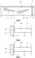
- the one in the Fig. 1 and 2 Catamaran 1 shown in two views has two floating bodies 2 and 3 and a drive fin 4, which extends in the transverse direction along a floating body distance 5 between the two floating bodies 2 and 3.
- the drive fin extends between mutually parallel wall regions 6 and 7 of the floating bodies 2 and 3, essentially spanning the floating body distance 5, ie ending within a maximum distance 8 of 20 mm from the wall regions 6 and 7.
- the drive fin 5 is moved up and down below a water surface 23 to drive the catamaran 1, which is indicated by arrows 9 and 10 in Fig. 1 is indicated.
- the drive fin 4 moves below does not extend beyond the floating bodies 2 and 3 and is therefore protected by the floating bodies 2 and 3 from collisions with the bottom of the respective body of water or other obstacles.
- the movement is caused by a guide and drive mechanism 11, which is in Fig. 1 is indicated schematically.
- the guide and drive mechanism 11 has a pedal crank 13 provided with pedals 12 as an input element 14, which can be operated with muscle power.
- the guidance and drive mechanism includes an auxiliary motor 15, in particular in the form of an electric motor, in order to add additional force and thus drive power to the muscle power.
- the pedal crank and possibly also a seat, not shown here, for a person pedaling the pedal crank 13 are mounted on a platform 16, on the underside of which the floating bodies 2 and 3 are attached.
- rudders 17 and 18 are mounted on the rear ends of the floating bodies 2 and 3 so that they can be pivoted about vertical pivot axes 19 and 20.
- the direction of travel of the catamaran 1 can be controlled by pivoting the rudders 17 and 18.
- the two control rudders 17 and 18 are rigidly coupled to one another with respect to their pivoting movements about the vertical pivot axes 19 and 20 by an articulated coupling rod 21.
- the vertical section according to Fig. 3 shows the drive fin 6 in a different position than Fig. 1 , at the beginning of their downward movement in the direction of arrow 10.
- a downward movement about a transverse axis 22 lying far in front of the front edge of the drive fin 4 is provided.
- the drive fin 4 is therefore not moved vertically up and down, but is pivoted about the transverse axis 22 at the same time.
- Fig.4 shows in one Fig. 3 corresponding sectional view of the stern of another catamaran according to the invention, in which two drive fins 4 and 24 are arranged one above the other. Regardless of the number of drive fins, they are according to Fig. 4 pivoted about a transverse axis 22 running in the area of its front edges and thereby moved up and down.
- the drive fins 4 and 24 are designed to be elastically deformable and are correspondingly deformed by the resistance of the water, as shown in Fig. 4 is shown. Pivoting the drive fins 4 and 24 about the transverse axes 22 running in the area of their front edges is possible by simply mounting the drive fins 4 and 24 on shafts running along the transverse axes 22. From the guiding and driving mechanism These shafts just have to be rotated back and forth. This corresponds to a particularly simple embodiment of the guide and drive mechanism 11.
- Fig. 5 shows an embodiment of the catamaran 1 with two drive fins 4 and 24 arranged one behind the other. Unlike the drive fins 4 and 24 arranged one above the other according to Fig. 4 The drive fins 4 and 24 arranged one behind the other are according to Fig. 5 but moves up and down in opposite directions under the water surface 23. In addition, in the embodiment according to Fig. 5 the drive fins 4 and 24 move vertically up and down with their front edges in a straight line, whereby they are designed to be elastic, so that they are additionally deformed around transverse axes. A rigid flat plate would not propel the catamaran in a linear up and down movement.
- Fig. 6 shows an enlarged view of how the side edge 25 of the drive fin 4 ends within the maximum distance 8 of at most 20 mm from the wall area 6. Maintaining the maximum distance 8 ensures that a lateral flow around the drive fin 4, which reduces the efficiency of the fin drive, is also prevented where the greatest pressure difference occurs across the side edge 25 between the top 26 and the bottom 27 of the drive fin 4.
- the drive fin 4 lies against the wall area 6 in the area of its side edge 25 with sealing lips 28.
- the sealing lips 28 do not actually have to rest against the wall region 6 in every position of the drive fin 24 relative to the wall region 6. Due to the deformable sealing lips 28, however, a very small maximum distance 8, which hinders the lateral flow around the drive fin 24, can be maintained because any tolerances and deformations of the catamaran 1 according to the invention are compensated for by the flexibility of the sealing lips 28.
- a movable connecting element 30 is rotatably mounted on the drive fin 4 about an axis of rotation 31 running along the side edge 25 and is at the same time elastically acted upon against the wall region 6 by an elastic element 32 outlined as a spring. So the connecting element always lies directly against the wall area 6, even beyond tolerances, which is here provided with a surface reinforcement 33 so as not to be damaged by the rolling connecting element 30.
- the movable connection element 30 closes the gap between the side edge 25 and the wall area 6 and thus effectively prevents a lateral flow around the drive fin 4.
Landscapes
- Chemical & Material Sciences (AREA)
- Engineering & Computer Science (AREA)
- Combustion & Propulsion (AREA)
- Mechanical Engineering (AREA)
- Ocean & Marine Engineering (AREA)
- Toys (AREA)
Claims (11)
- Catamaran (1) avec- deux flotteurs (2, 3) qui sont disposés à côté l'un de l'autre dans la direction transversale, à une distance entre flotteurs (5) limitée par les parties de parois parallèles (6, 7) des flotteurs (2, 3),- un aileron d'entraînement (4), qui s'étend dans la direction transversale le long de la distance entre les flotteurs (5) et- un mécanisme de guidage et d'entraînement (11) qui est conçu pour déplacer vers le haut et vers le bas l'aileron d'entraînement (4) entre les flotteurs (2, 3), dans lequel l'aileron d'entraînement (4) peut être pivoté et/ou déformé activement et/ou passivement autour d'un axe transversal (22),dans lequel l'aileron d'entraînement (4) déplacé vers le haut et vers le bas s'étend entre les parties de parois (6, 7) parallèles entre elles des flotteurs (2, 3) et dans lequel l'aileron d'entraînement (4) déplacé vers le haut et vers le bas se déplace vers le bas pas au-delà des flotteurs (2, 3), caractérisé en ce que l'aileron d'entraînement (3) se déplace vers le haut et vers le bas en dessous de la surface de l'eau (23),et en ce que l'aileron d'entraînement (4) se termine, dans respectivement au moins une zone de ses deux arêtes latérales (25), qui est déplacée vers le haut et vers le bas par le mécanisme de guidage et d'entraînement (11) par rapport aux parties de parois (6, 7), à l'intérieur d'une distance maximale (8) de 20 mm des parties de parois (6, 7).
- Catamaran (1) selon la revendication 1, caractérisé en ce que l'aileron d'entraînement (4) se termine, dans respectivement au moins une zone de ses deux arêtes latérales (25), par l'intermédiaire de laquelle la plus grande différence de pression se forme, lorsque l'aileron d'entraînement (4) est déplacé vers le haut et vers le bas par le mécanisme de guidage et d'entraînement (11), à l'intérieur de la distance maximale (8) de 20 mm des parties de parois (6, 7).
- Catamaran (1) selon la revendication 2, caractérisé en ce que l'aileron d'entraînement (4) se termine, sur au moins 50 %, de préférence sur au moins 75 % des longueurs de ses arêtes latérales (25), à l'intérieur de la distance maximale (8) de 20 mm des parties de parois (6, 7).
- Catamaran (1) selon la revendication 3, caractérisé en ce que l'aileron d'entraînement (4) se termine, sur toutes les longueurs de ses arêtes latérales (25), à l'intérieur de la distance maximale (8) de 20 mm des parties de parois (6, 7).
- Catamaran (1) selon l'une des revendications précédentes, caractérisé en ce que la distance maximale (8) est de 10 mm, de préférence de 15 mm.
- Catamaran (1) selon l'une des revendications précédentes, caractérisé en ce que l'aileron d'entraînement (4) s'appuie contre les parties de parois (6, 7) par l'intermédiaire d'éléments de raccordement flexible et/ou mobiles (30), dans lequel, de préférence, des éléments élastiques sont prévus, qui compriment les éléments de raccordement contre les parties de parois (6, 7).
- Catamaran (1) selon la revendication 6, caractérisé en ce que les éléments de raccordement flexibles comprennent des lèvres d'étanchéité (28) et/ou des corps à brosses (29) et/ou en ce que les éléments de raccordement mobiles (30) sont logés sur l'aileron d'entraînement (4) de manière rotative autour d'axes de rotation (31), dans lequel les axes de rotation (31) sont orientés le long des arêtes latérales (25) de l'aileron d'entraînement (4).
- Catamaran (1) selon l'une des revendications précédentes, caractérisé en ce que deux ailerons d'entraînement (4, 24) sont superposés et le mécanisme de guidage et d'entraînement (11) est conçu pour déplacer vers le haut et vers le bas, dans le même sens, entre les flotteurs (2, 3), les deux ailerons d'entraînement (4, 24) superposés.
- Catamaran (1) selon l'une des revendications précédentes, caractérisé en ce que deux ailerons d'entraînement (4, 24) sont disposés l'un derrière l'autre et le mécanisme de guidage et d'entraînement (11) est conçu pour déplacer vers le haut et vers le bas, dans le même sens, entre les flotteurs (2, 3), les deux ailerons d'entraînement (4, 24) disposés l'un derrière l'autre.
- Catamaran (1) selon l'une des revendications précédentes, caractérisé en ce que le mécanisme de guidage et d'entraînement (11) comprend un élément d'entrée (14) actionnable par la force musculaire, plus particulièrement un pédalier (13) muni de pédales (12).
- Catamaran (1) selon l'une des revendications précédentes, caractérisé en ce que le mécanisme de guidage et d'entraînement (11) comprend un élément d'entrée (14) pouvant être entraîné avec un moteur, plus particulièrement avec un moteur électrique configuré comme un moteur auxiliaire (15).
Applications Claiming Priority (1)
| Application Number | Priority Date | Filing Date | Title |
|---|---|---|---|
| DE102021128230.6A DE102021128230B3 (de) | 2021-10-29 | 2021-10-29 | Katamaran mit Flossenantrieb |
Publications (3)
| Publication Number | Publication Date |
|---|---|
| EP4173943A1 EP4173943A1 (fr) | 2023-05-03 |
| EP4173943B1 true EP4173943B1 (fr) | 2024-01-24 |
| EP4173943C0 EP4173943C0 (fr) | 2024-01-24 |
Family
ID=83996463
Family Applications (1)
| Application Number | Title | Priority Date | Filing Date |
|---|---|---|---|
| EP22203538.8A Active EP4173943B1 (fr) | 2021-10-29 | 2022-10-25 | Catamaran à propulsion à ailerons |
Country Status (2)
| Country | Link |
|---|---|
| EP (1) | EP4173943B1 (fr) |
| DE (1) | DE102021128230B3 (fr) |
Family Cites Families (12)
| Publication number | Priority date | Publication date | Assignee | Title |
|---|---|---|---|---|
| DE840517C (de) | 1951-01-09 | 1952-06-03 | Ernst Dipl-Ing Langhans | Flossenantrieb fuer Wasserfahrzeuge, bei dem eine Hauptflosse hin- und hergeschwenkt wird |
| DE1531748A1 (de) | 1966-09-07 | 1970-01-08 | Gause Joseph Arnost | Flexible Antriebsflosse fuer Wasserfahrzeuge mit dem zugehoerigen Antrieb |
| GB1236194A (en) | 1968-01-30 | 1971-06-23 | Joachim Spangenberg | Improvements in or relating to motorless water-borne vehicles |
| FR2359744A1 (fr) | 1976-07-29 | 1978-02-24 | Roche Kerandraon Saulses Freyc | Dispositif de propulsion perfectionne pour les navires |
| FR2565549A1 (fr) | 1984-06-07 | 1985-12-13 | Guimbal Jean | Bateau de tourisme sans moteur |
| SU1634568A1 (ru) * | 1989-01-02 | 1991-03-15 | Предприятие П/Я В-2141 | Судовой движитель |
| DE4212920C2 (de) | 1992-04-15 | 1995-03-23 | Erich Dr Ing Henker | Flossenantrieb mit Muskelkraft für Wasserfahrzeuge |
| DE19515114A1 (de) | 1994-11-02 | 1996-05-09 | Erich Dr Ing Henker | Flossenantrieb mit Muskelkraft für Wasserfahrzeuge |
| DE102004004236A1 (de) | 2004-01-27 | 2005-09-08 | Kludszuweit, Alfred | Antriebsgetriebe für Flossenantriebe von Schwimmkörpern |
| EP2225149B1 (fr) | 2007-12-10 | 2012-06-06 | A.P. Moller - Maersk A/S | Element d'etancheite pour propulsion a ailerons |
| CN102164816B (zh) | 2008-08-18 | 2014-07-09 | 振荡翼片发展有限责任公司 | 用于在流体中摆动翼片的设备、相关船及装置 |
| CN109733528A (zh) | 2019-02-15 | 2019-05-10 | 哈尔滨工程大学 | 一种船用仿生喷水推进装置 |
-
2021
- 2021-10-29 DE DE102021128230.6A patent/DE102021128230B3/de not_active Expired - Fee Related
-
2022
- 2022-10-25 EP EP22203538.8A patent/EP4173943B1/fr active Active
Also Published As
| Publication number | Publication date |
|---|---|
| DE102021128230B3 (de) | 2022-12-01 |
| EP4173943A1 (fr) | 2023-05-03 |
| EP4173943C0 (fr) | 2024-01-24 |
Similar Documents
| Publication | Publication Date | Title |
|---|---|---|
| DE3005682C2 (de) | Schiffantriebsanlage | |
| EP2616318B1 (fr) | Navire avec une passerelle d'embarquement | |
| EP2060485B1 (fr) | Agencement de gouvernail pour bateaux à vitesses élevées et d'un gouvernail réduisant la cavitation, torsadé, en particulier gouvernail à suspension totale | |
| DE102011118844B3 (de) | Vertikalwindturbine und Rotorblatt hierfür | |
| DE2757454C3 (de) | Wasserstrahlantrieb zum Antrieb und Steuern von insbesondere flachgehenden Wasserfahrzeugen | |
| DE3126371A1 (de) | Vorrichtung zur stabilisierung der fahrtrichtung von wasserfahrzeugen, insbesondere schwert oder finne fuer windsurfbretter | |
| EP1979228A1 (fr) | Bateau comprenant un flotteur | |
| DE2820355A1 (de) | Ruder fuer wasserfahrzeuge und schwimmendes geraet | |
| DE19747561A1 (de) | Wasserstrahlsystem | |
| DE60216015T2 (de) | Aussenbordmotor | |
| EP3544887B1 (fr) | Buse d'une hélice de navire | |
| DE69009372T2 (de) | Verringerung des Wellenwiderstandes eines Schiffes. | |
| DE8207403U1 (de) | Fluegelsegel | |
| EP1508516A1 (fr) | Systeme compact de propulsion et de direction par jet d'eau | |
| DE102009026382A1 (de) | Schaufelrad mit drehbaren Schaufeln und Verfahren zur Stellung der drehbaren Schaufeln | |
| DE2318788C2 (de) | Hochgeschwindigkeitswasserfahrzeug | |
| DE102021128230B3 (de) | Katamaran mit Flossenantrieb | |
| DE2918751A1 (de) | Ruderbremsvorrichtung | |
| EP0909703B1 (fr) | Gouvernail pour bateaux | |
| DE4204110A1 (de) | Schiff | |
| WO2003011685A1 (fr) | Propulsion par jet d'eau pour bateaux | |
| DE19841392B4 (de) | Hochlast-Schweberuder | |
| DE202009019046U1 (de) | Schiff mit einer diesel-elektrischen Antriebsvorrichtung | |
| EP1787904B1 (fr) | Gouvernail suspendu à hautes sollicitations | |
| DE2438305A1 (de) | Querschubanlage fuer ein schiff |
Legal Events
| Date | Code | Title | Description |
|---|---|---|---|
| PUAI | Public reference made under article 153(3) epc to a published international application that has entered the european phase |
Free format text: ORIGINAL CODE: 0009012 |
|
| STAA | Information on the status of an ep patent application or granted ep patent |
Free format text: STATUS: THE APPLICATION HAS BEEN PUBLISHED |
|
| AK | Designated contracting states |
Kind code of ref document: A1 Designated state(s): AL AT BE BG CH CY CZ DE DK EE ES FI FR GB GR HR HU IE IS IT LI LT LU LV MC ME MK MT NL NO PL PT RO RS SE SI SK SM TR |
|
| STAA | Information on the status of an ep patent application or granted ep patent |
Free format text: STATUS: REQUEST FOR EXAMINATION WAS MADE |
|
| 17P | Request for examination filed |
Effective date: 20230711 |
|
| GRAP | Despatch of communication of intention to grant a patent |
Free format text: ORIGINAL CODE: EPIDOSNIGR1 |
|
| STAA | Information on the status of an ep patent application or granted ep patent |
Free format text: STATUS: GRANT OF PATENT IS INTENDED |
|
| INTG | Intention to grant announced |
Effective date: 20230905 |
|
| RBV | Designated contracting states (corrected) |
Designated state(s): AL AT BE BG CH CY CZ DE DK EE ES FI FR GB GR HR HU IE IS IT LI LT LU LV MC ME MK MT NL NO PL PT RO RS SE SI SK SM TR |
|
| GRAS | Grant fee paid |
Free format text: ORIGINAL CODE: EPIDOSNIGR3 |
|
| GRAA | (expected) grant |
Free format text: ORIGINAL CODE: 0009210 |
|
| STAA | Information on the status of an ep patent application or granted ep patent |
Free format text: STATUS: THE PATENT HAS BEEN GRANTED |
|
| AK | Designated contracting states |
Kind code of ref document: B1 Designated state(s): AL AT BE BG CH CY CZ DE DK EE ES FI FR GB GR HR HU IE IS IT LI LT LU LV MC ME MK MT NL NO PL PT RO RS SE SI SK SM TR |
|
| REG | Reference to a national code |
Ref country code: GB Ref legal event code: FG4D Free format text: NOT ENGLISH |
|
| REG | Reference to a national code |
Ref country code: CH Ref legal event code: EP |
|
| REG | Reference to a national code |
Ref country code: IE Ref legal event code: FG4D Free format text: LANGUAGE OF EP DOCUMENT: GERMAN |
|
| REG | Reference to a national code |
Ref country code: DE Ref legal event code: R096 Ref document number: 502022000430 Country of ref document: DE |
|
| U01 | Request for unitary effect filed |
Effective date: 20240222 |
|
| U07 | Unitary effect registered |
Designated state(s): AT BE BG DE DK EE FI FR IT LT LU LV MT NL PT SE SI Effective date: 20240229 |
|
| REG | Reference to a national code |
Ref country code: LT Ref legal event code: MG9D |
|
| PG25 | Lapsed in a contracting state [announced via postgrant information from national office to epo] |
Ref country code: IS Free format text: LAPSE BECAUSE OF FAILURE TO SUBMIT A TRANSLATION OF THE DESCRIPTION OR TO PAY THE FEE WITHIN THE PRESCRIBED TIME-LIMIT Effective date: 20240524 |
|
| PG25 | Lapsed in a contracting state [announced via postgrant information from national office to epo] |
Ref country code: GR Free format text: LAPSE BECAUSE OF FAILURE TO SUBMIT A TRANSLATION OF THE DESCRIPTION OR TO PAY THE FEE WITHIN THE PRESCRIBED TIME-LIMIT Effective date: 20240425 |
|
| PG25 | Lapsed in a contracting state [announced via postgrant information from national office to epo] |
Ref country code: HR Free format text: LAPSE BECAUSE OF FAILURE TO SUBMIT A TRANSLATION OF THE DESCRIPTION OR TO PAY THE FEE WITHIN THE PRESCRIBED TIME-LIMIT Effective date: 20240124 Ref country code: RS Free format text: LAPSE BECAUSE OF FAILURE TO SUBMIT A TRANSLATION OF THE DESCRIPTION OR TO PAY THE FEE WITHIN THE PRESCRIBED TIME-LIMIT Effective date: 20240424 |
|
| PG25 | Lapsed in a contracting state [announced via postgrant information from national office to epo] |
Ref country code: ES Free format text: LAPSE BECAUSE OF FAILURE TO SUBMIT A TRANSLATION OF THE DESCRIPTION OR TO PAY THE FEE WITHIN THE PRESCRIBED TIME-LIMIT Effective date: 20240124 |
|
| PG25 | Lapsed in a contracting state [announced via postgrant information from national office to epo] |
Ref country code: RS Free format text: LAPSE BECAUSE OF FAILURE TO SUBMIT A TRANSLATION OF THE DESCRIPTION OR TO PAY THE FEE WITHIN THE PRESCRIBED TIME-LIMIT Effective date: 20240424 Ref country code: NO Free format text: LAPSE BECAUSE OF FAILURE TO SUBMIT A TRANSLATION OF THE DESCRIPTION OR TO PAY THE FEE WITHIN THE PRESCRIBED TIME-LIMIT Effective date: 20240424 Ref country code: IS Free format text: LAPSE BECAUSE OF FAILURE TO SUBMIT A TRANSLATION OF THE DESCRIPTION OR TO PAY THE FEE WITHIN THE PRESCRIBED TIME-LIMIT Effective date: 20240524 Ref country code: HR Free format text: LAPSE BECAUSE OF FAILURE TO SUBMIT A TRANSLATION OF THE DESCRIPTION OR TO PAY THE FEE WITHIN THE PRESCRIBED TIME-LIMIT Effective date: 20240124 Ref country code: GR Free format text: LAPSE BECAUSE OF FAILURE TO SUBMIT A TRANSLATION OF THE DESCRIPTION OR TO PAY THE FEE WITHIN THE PRESCRIBED TIME-LIMIT Effective date: 20240425 Ref country code: ES Free format text: LAPSE BECAUSE OF FAILURE TO SUBMIT A TRANSLATION OF THE DESCRIPTION OR TO PAY THE FEE WITHIN THE PRESCRIBED TIME-LIMIT Effective date: 20240124 |
|
| PG25 | Lapsed in a contracting state [announced via postgrant information from national office to epo] |
Ref country code: PL Free format text: LAPSE BECAUSE OF FAILURE TO SUBMIT A TRANSLATION OF THE DESCRIPTION OR TO PAY THE FEE WITHIN THE PRESCRIBED TIME-LIMIT Effective date: 20240124 |
|
| PG25 | Lapsed in a contracting state [announced via postgrant information from national office to epo] |
Ref country code: PL Free format text: LAPSE BECAUSE OF FAILURE TO SUBMIT A TRANSLATION OF THE DESCRIPTION OR TO PAY THE FEE WITHIN THE PRESCRIBED TIME-LIMIT Effective date: 20240124 |
|
| U20 | Renewal fee for the european patent with unitary effect paid |
Year of fee payment: 3 Effective date: 20240801 |
|
| PG25 | Lapsed in a contracting state [announced via postgrant information from national office to epo] |
Ref country code: SM Free format text: LAPSE BECAUSE OF FAILURE TO SUBMIT A TRANSLATION OF THE DESCRIPTION OR TO PAY THE FEE WITHIN THE PRESCRIBED TIME-LIMIT Effective date: 20240124 |
|
| PG25 | Lapsed in a contracting state [announced via postgrant information from national office to epo] |
Ref country code: CZ Free format text: LAPSE BECAUSE OF FAILURE TO SUBMIT A TRANSLATION OF THE DESCRIPTION OR TO PAY THE FEE WITHIN THE PRESCRIBED TIME-LIMIT Effective date: 20240124 |
|
| REG | Reference to a national code |
Ref country code: DE Ref legal event code: R097 Ref document number: 502022000430 Country of ref document: DE |
|
| PG25 | Lapsed in a contracting state [announced via postgrant information from national office to epo] |
Ref country code: SK Free format text: LAPSE BECAUSE OF FAILURE TO SUBMIT A TRANSLATION OF THE DESCRIPTION OR TO PAY THE FEE WITHIN THE PRESCRIBED TIME-LIMIT Effective date: 20240124 |
|
| PG25 | Lapsed in a contracting state [announced via postgrant information from national office to epo] |
Ref country code: SM Free format text: LAPSE BECAUSE OF FAILURE TO SUBMIT A TRANSLATION OF THE DESCRIPTION OR TO PAY THE FEE WITHIN THE PRESCRIBED TIME-LIMIT Effective date: 20240124 Ref country code: SK Free format text: LAPSE BECAUSE OF FAILURE TO SUBMIT A TRANSLATION OF THE DESCRIPTION OR TO PAY THE FEE WITHIN THE PRESCRIBED TIME-LIMIT Effective date: 20240124 Ref country code: CZ Free format text: LAPSE BECAUSE OF FAILURE TO SUBMIT A TRANSLATION OF THE DESCRIPTION OR TO PAY THE FEE WITHIN THE PRESCRIBED TIME-LIMIT Effective date: 20240124 |
|
| PLBE | No opposition filed within time limit |
Free format text: ORIGINAL CODE: 0009261 |
|
| STAA | Information on the status of an ep patent application or granted ep patent |
Free format text: STATUS: NO OPPOSITION FILED WITHIN TIME LIMIT |
|
| 26N | No opposition filed |
Effective date: 20241025 |
|
| PG25 | Lapsed in a contracting state [announced via postgrant information from national office to epo] |
Ref country code: MC Free format text: LAPSE BECAUSE OF FAILURE TO SUBMIT A TRANSLATION OF THE DESCRIPTION OR TO PAY THE FEE WITHIN THE PRESCRIBED TIME-LIMIT Effective date: 20240124 |
|
| U20 | Renewal fee for the european patent with unitary effect paid |
Year of fee payment: 4 Effective date: 20250811 |
|
| PG25 | Lapsed in a contracting state [announced via postgrant information from national office to epo] |
Ref country code: IE Free format text: LAPSE BECAUSE OF NON-PAYMENT OF DUE FEES Effective date: 20241025 |
|
| PG25 | Lapsed in a contracting state [announced via postgrant information from national office to epo] |
Ref country code: RO Free format text: LAPSE BECAUSE OF FAILURE TO SUBMIT A TRANSLATION OF THE DESCRIPTION OR TO PAY THE FEE WITHIN THE PRESCRIBED TIME-LIMIT Effective date: 20240124 |
|
| PG25 | Lapsed in a contracting state [announced via postgrant information from national office to epo] |
Ref country code: CY Free format text: LAPSE BECAUSE OF FAILURE TO SUBMIT A TRANSLATION OF THE DESCRIPTION OR TO PAY THE FEE WITHIN THE PRESCRIBED TIME-LIMIT; INVALID AB INITIO Effective date: 20221025 |
|
| PG25 | Lapsed in a contracting state [announced via postgrant information from national office to epo] |
Ref country code: HU Free format text: LAPSE BECAUSE OF FAILURE TO SUBMIT A TRANSLATION OF THE DESCRIPTION OR TO PAY THE FEE WITHIN THE PRESCRIBED TIME-LIMIT; INVALID AB INITIO Effective date: 20221025 |