EP4174012A1 - Moyen de réception de charge et dispositif de réception de charge - Google Patents
Moyen de réception de charge et dispositif de réception de charge Download PDFInfo
- Publication number
- EP4174012A1 EP4174012A1 EP22203588.3A EP22203588A EP4174012A1 EP 4174012 A1 EP4174012 A1 EP 4174012A1 EP 22203588 A EP22203588 A EP 22203588A EP 4174012 A1 EP4174012 A1 EP 4174012A1
- Authority
- EP
- European Patent Office
- Prior art keywords
- locking
- load
- pull tab
- base element
- load handling
- Prior art date
- Legal status (The legal status is an assumption and is not a legal conclusion. Google has not performed a legal analysis and makes no representation as to the accuracy of the status listed.)
- Pending
Links
Images


Classifications
-
- B—PERFORMING OPERATIONS; TRANSPORTING
- B66—HOISTING; LIFTING; HAULING
- B66C—CRANES; LOAD-ENGAGING ELEMENTS OR DEVICES FOR CRANES, CAPSTANS, WINCHES, OR TACKLES
- B66C1/00—Load-engaging elements or devices attached to lifting or lowering gear of cranes or adapted for connection therewith for transmitting lifting forces to articles or groups of articles
- B66C1/10—Load-engaging elements or devices attached to lifting or lowering gear of cranes or adapted for connection therewith for transmitting lifting forces to articles or groups of articles by mechanical means
- B66C1/42—Gripping members engaging only the external or internal surfaces of the articles
- B66C1/44—Gripping members engaging only the external or internal surfaces of the articles and applying frictional forces
- B66C1/54—Internally-expanding grippers for handling hollow articles
Definitions
- the invention relates to a lifting device, in particular a lifting clamp, which can be used, for example, to lift wooden panel walls.
- the invention also relates to a load-carrying arrangement comprising at least two such load-carrying means.
- Load handling devices of the type mentioned are already known in a wide variety of embodiments and are used for lifting a wide variety of loads.
- the object of the invention is to provide a load-carrying device of the type mentioned at the outset, which is particularly suitable for handling wooden panel components without damaging them visibly from the outside by attaching the load-carrying device.
- a load handling device with the features of independent claim 1 is first proposed.
- a load-carrying device in particular a lifting clamp, is proposed, in particular, with a base element, a pull strap movably mounted on the base element and at least one expanding leg pivotable between an initial position and a spread position and mounted on the base element, the pull strap being connected via a coupling element, for example via a coupling rod, is connected to the at least one spreader leg in such a way that the at least one spreader leg can be moved by moving the pull tab relative to the base element between the initial position and the spread position.
- a preferably linear movement of the pull tab caused by a pull on the pull tab can in this way be converted into a movement of the expansion leg are implemented in its spread position or at least in the direction of its spread position.
- the at least one expansion leg can preferably be mounted pivotably on the base element and thus pivoted between its initial position and its expanded position on the base element.
- the at least one expansion leg In the starting position, the at least one expansion leg can be folded in and/or approached to the base element with its free end and/or arranged within a receiving space defined by the base element.
- the at least one expansion leg In the initial position, the at least one expansion leg can be stowed away in the base element.
- the at least one spreader leg In the spread position, the at least one spreader leg can be folded out and/or its free end can be further away from the base element than in the starting position.
- the coupling element is preferably designed as a coupling rod. This enables a transfer of tension and pressure between the pull tab and the at least one expansion leg.
- a coupling element can be assigned to each expansion leg of the load handling device.
- the coupling element is connected to the pull tab via a joint and to the spreader leg via a joint.
- the at least one expansion leg can be moved into the expanded position by a pulling movement of the pull tab in the direction of its free end.
- the load-carrying means has two spreader arms, which are each mounted on the base element so that they can be moved, preferably pivoted, between an initial position and a spread position.
- the pull tab can be connected to each of the two spreader legs via a respective coupling element.
- a load-carrying means is provided that can hook particularly reliably in a receiving opening of a load and that is therefore particularly suitable for lifting even comparatively heavy loads, such as wooden panel components.
- Each coupling element is preferably connected to the pull tab via a joint and to its respective expansion leg via a joint.
- the two spreader legs of the load-carrying means are arranged on two different sides of the pull strap of the load-carrying means.
- the load handling device is given a symmetrical structure, at least in relation to the two expansion legs uniform application of force when lifting a load in the load handling device.
- the pull tab can be mounted so that it can move linearly on the base element and/or between the expansion legs. A movement of the pull tab, in particular a linear movement of the pull tab, can thus take place between the two expansion legs.
- the linear movement of the pull tab can be converted into a movement, in particular into a pivoting movement of the two spreader legs, via the coupling elements.
- the coupling elements can be aligned at an acute angle to a longitudinal center axis and/or to a direction of movement of the pull tab. In this way, it is ensured that a tensile force that is transferred to the pull tab when a load connected to the load handling device is lifted is reliably converted into a clamping force with which the load handling device can be releasably fixed to the load.
- the above-mentioned acute angle between the coupling elements and the longitudinal center axis and/or to the direction of movement of the pull strap is also advantageous in order to be able to detach the load handling device from the load.
- the pull tab can have a suspension point, for example an eyelet, for suspending a hoist.
- the load handling device can be attached to a hoist via the pull strap and the pull strap when lifting from a starting position in which the at least one spreader leg is applied or folded in, move to an extended position.
- the preferably linear movement of the pull tab in the pull direction is converted into the movement, preferably into the pivoting movement of the at least one spreader leg from its initial position into a spread position spread apart from the base element.
- the load-carrying device can be automatically fixed to the load to be lifted when a tensile force is transferred to the load to be lifted via the pull strap of the load-carrying device.
- the free end of the pull tab can be the end of the pull tab that faces away from the base element of the load handling device.
- this has a locking device.
- the locking device can be set up to lock the at least one expansion leg in its applied initial position and/or in an intermediate position between the initial position and the expanded position.
- Locking the at least one expansion leg in its initial position can be helpful in order to lift the load handling device by pulling on the pull strap and thereby separating it from the load to be lifted, without the at least one expansion leg being moved from its initial position into its spread position by the pull on the pull strap is moved in which it would prevent the load handling attachment from separating from the load to be lifted, as intended.
- the locking of the expansion leg thus serves to hold the expansion leg in its initial position independently of a load on the pull tab.
- Locking the at least one spreader leg in an intermediate position between the initial position and the spread position can be helpful if the Load handling equipment is to be used in an opening of a load which is formed in an inclined surface of the load and/or which has a longitudinal central axis which is oriented obliquely to the direction of gravity.
- Such a situation can arise, for example, in the case of so-called gable walls, that is to say wooden panel construction walls which have a gable.
- openings for inserting the load-carrying means are often arranged on an inclined surface and then have longitudinal center axes oriented obliquely to the direction of gravity.
- the at least one expansion leg can be moved from its initial position into an already slightly expanded expanded position by pulling on the pull tab.
- the locking of the at least one expansion leg in the intermediate position outlined above can be used to keep the load handling device fixed to a load in an obliquely oriented insertion opening and to prevent the load handling device from being pulled out of the insertion opening before the at least one expanding leg is properly expanded has.
- the at least one expansion leg is locked in the intermediate position with play, ie with room to move.
- the locking of the expansion leg in the position can therefore be designed in such a way that the expansion leg can still cover a remaining adjustment path from its locked intermediate position to its proper spread position by pulling on the pull tab.
- the Locking of the at least one expansion leg in its intermediate position can thus be understood as a lower stop, which effectively prevents the expansion leg from returning from the intermediate position to its starting position, for example due to the force of gravity.
- An upper stop which defines the spread position of the at least one spreader leg, can be provided between the base element and the pull tab and/or between the base element and the at least one spreader leg.
- the pull strap has a guide recess, for example a longitudinal slot, the upper edge of which can define the starting position and the lower edge of which can define the maximum spread position of the at least one spreader leg.
- the base element can have a guide element that fits the guide recess, which serves to limit the travel of the pull tab and is arranged on the base element in the guide recess of the pull tab when the pull tab is in the position of use.
- the length of the guide recess which is preferably designed as a longitudinal slot, and the guide element on the base element can then define a maximum linear adjustment path for the pull tab on the base element.
- the locking device has at least one actuating lever for activating and/or releasing the locking.
- the locking device can have an actuating lever for locking in the initial position and for locking in the intermediate position. In this way it is possible to activate or release the locking for the intermediate position and also the locking for the starting position separately from one another. It can be advantageous if the actuating lever or levers is/are set up to to be connected to a pulling element, for example a rope, a cord or a cable. In this way it is possible to actuate the actuating lever or levers of the lock in a simple manner, even from a distance.
- a pulling element for example a rope, a cord or a cable.
- an electrical, in particular an electromechanical, actuating device is provided for actuating the locking device for activating and/or releasing the locking.
- the locking device for locking the at least one expansion leg in the starting position can have a locking bolt and a bolt receptacle.
- the bolt receptacle can be formed on the pull tab and the locking bolt can engage in the bolt receptacle in the locking position in order to fix the pull tab in its initial position on the base element. If the bolt receptacle for locking the at least one expansion leg in the starting position has no or only a minimal oversize compared to the locking bolt, the locking bolt and thus ultimately also the expansion leg can be fixed in the starting position without play or largely without play.
- the locking device for locking the at least one expansion leg in the intermediate position has a locking bolt and a bolt receptacle.
- the bolt receptacle can be formed on the pull tab and the locking bolt can engage in the bolt receptacle in the locking position in order to fix the pull tab in an intermediate position on the base element.
- the bolt receptacle for the intermediate position can preferably be an elongated hole aligned in the direction of movement of the pull tab to the base element and/or have an oversize in the direction of movement of the pull tab to the base element compared to a cross section of the locking pin relevant for locking. In this way it is possible to lock the to provide at least one expansion leg in the intermediate position with the aforementioned play.
- the pull tab can be moved further in the pulling direction within the limits specified by the bolt receptacle, so that by pulling on the pull tab, the at least one expansion leg can be removed from the Intermediate position can still be moved into the spread position.
- At least one locking bolt preferably both of the aforementioned locking bolts, can be movably mounted on the base element between a locking position and a release position. It can be advantageous if at least one locking bolt, preferably both locking bolts, is/are movably mounted against a restoring force of one, preferably one in each case, restoring element from its arresting position into a release position or vice versa. The restoring force of the restoring element ensures that the locking bolt remains in its respective locking position or in its release position when the locking device is not actuated.
- the locking bolt for locking the at least one expansion leg in the starting position i.e. in the position in which the at least one expansion leg is folded in and the load suspension device is not fixed in a corresponding insertion opening of a load, against the action of a Restoring element from the locked position is movable into a release position. This ensures that the locking bolt remains in its locking position when the locking device is not actuated.
- the locking bolt for locking the at least one expansion leg is movable in its intermediate position against a restoring force of a restoring element from its release position into its locking position.
- the restoring element can be prestressed.
- the locking can thus be released automatically and easily by actuating or possibly remotely actuating the actuating lever assigned to the locking bolt for locking the at least one expansion leg in its intermediate position. If the actuating lever is moved into a release position, the restoring element relaxes and the locking bolt can be moved by the restoring element from its locking position into its release position and the at least one expanding leg can be moved back into its folded-in initial position without restrictions by the locking bolt.
- the locking of the at least one expansion leg in its initial position can be activated. This is possible by actuating or possibly remotely actuating the actuating lever of the locking device, which is assigned to the locking bolt for locking the at least one expansion leg in its initial position. Due to the restoring force of the restoring spring, the locking bolt then automatically moves into its locking position when the actuating lever is actuated.
- a locking bolt namely preferably the locking bolt for the intermediate position of the at least one expansion leg, can be locked in its locking position, preferably with an actuating lever of the locking device, for example the one already mentioned above.
- At least one locking bolt in particular the locking bolt for the starting position, can be locked in a locking position. This preferably with one, for example with the previously mentioned actuating lever of the locking device.
- the at least one expansion leg can have a friction-increasing coating and/or a friction-increasing structure, for example teeth, on its contact surface facing a load in the position of use. In this way, it may be possible to transfer higher forces with the load handling device and, if necessary, to lift even higher loads.
- the load handling device has a fastening interface for fastening a spacer bar, in particular on its base element.
- Two or more load handling devices can be coupled to one another via a spacer rod in such a way that they maintain their position relative to one another. In this way it is possible to provide and lift a load with two or more of the aforementioned load handling devices. Not only the insertion of the load-carrying devices into corresponding insertion openings on the load to be lifted, but also the removal of the load-carrying devices from the insertion openings is considerably simplified by fixing the relative distance between the load-carrying devices by the spacer bar.
- a load-carrying arrangement comprising at least two load-carrying means is also proposed, the load-carrying means being connected to one another via a spacer bar.
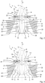
- All of the figures show at least one load-carrying means, designated as a whole by 1, which is designed as a lifting clamp.
- the load-carrying means 1 comprises a base element 2, a pull strap 3 which is movably mounted on the base element 2 and, respectively two movable between a starting position and a spread position, namely spreader leg 4 pivotally mounted on the base element 2.
- the expansion legs 4 are folded in and the base element 2 is brought closer to them with their free ends.
- the expansion legs 4 are at least partially arranged within a receiving space 33 defined by the base element 2 .
- the expansion legs 4 are stowed away in the base element 2 in this way.
- the spreader legs 4 are folded out and their free ends 34 are further away from the base element 2 than in the starting position.
- the pull strap 3 is connected to each of the two spreader legs 4 by a coupling element 5, which is designed as a coupling rod in the embodiment of the load handling device 1 shown in the figures, with the two spreader legs 4 in such a way that the spreader legs 4 can be moved by a movement of the pull strap 3 relative to the base element 2 of the lifting device between the initial position (see figure 2 ) and the spread position (see figure 3 ) are movable.
- the two coupling elements 5 each have two joints 31 and 32 in order to convert the movement of the pull tab 3 into a movement of the two expansion legs 4 .
- the coupling elements 5 are connected to the pull tab 3 via their joint, which is designated 31 in each case.
- the coupling elements 5 are connected to their expansion leg 4 via their joint, each designated 32 .
- the two expansion legs 4 can be opened by a pulling movement of the pull tab 3, which is figure 2 is illustrated by the arrow 6, in the direction of the free end 7 of the pull tab 3 in the spread position according to figure 3 be moved.
- the pull tab 3 has at its free end 7 a suspension point 8, namely an eyelet for suspending a hoist, not shown in detail in the figures. If the lifting device 1 is pulled in the direction of arrow 6 by the hoist pulling on the pull tab 3, the pull tab 3 reaches the in figure 1 position shown, whereby the two coupling elements 5 then also bring the expansion legs 4 into their expanded position and hold them there.
- figure 3 shows the load handling device 1 in its fixed position within an insertion opening 9 of a load 10 shown in section, in which the load 10, for example a wooden panel construction wall, can be lifted with the help of the load handling device 1.
- the insertion opening 9 in the load 10 is a slot that according to Figures 2 and 3 has a trapezoidal cross-section in the plane of the drawing.
- An inclined position of the wall of the insertion opening 9 is aligned with an inclined position of the two expansion legs 4 to a longitudinal central axis 11 of the pull tab 3, in the direction of which the pulling movement of the pull tab 3 also takes place.
- the load-carrying means 1 also has a locking device 12, with which the two expansion legs 4 in accordance with their applied initial position figure 2 and can also be locked in an intermediate position between the initial position and the spread position.
- figure 3 clarifies that the two expansion legs 4 are locked in the intermediate position with the aid of the locking device 12 with play, so that the pull tab 3 can still move a little in the pulling direction 6 and the two expansion legs 4 move out of the intermediate position into the in figure 3 spread position shown can move when the load-carrying means 1 is to be lifted with the load 10 attached to it.
- the locking device 12 also has two actuating levers 13 and 14 for activating and releasing the locking device 12 .
- one actuating lever 13 is used to actuate the locking device in the initial position, while the actuating lever 14 is used to actuate the locking device in the intermediate position.
- the locking device 12 has a locking bolt 15 and a corresponding bolt receptacle 16 .
- the bolt receptacle 16 is formed here on one side of the pull tab 3 and the locking bolt 15 engages in the bolt receptacle 16 in its locking position.
- the locking bolt 15 engages in the bolt receptacle 16 in order to fix the pull tab 3 and thereby also the two spreader legs 4 in their initial position on the base element 2, ie the spreader legs 4 in the folded position according to FIG figure 2 to keep.
- the load-carrying means 1 can simply be inserted into the insertion opening 9 of the load 10 .
- the locking bolt 15 must first be moved out of its bolt receptacle 16 . This is done by actuating the actuating lever 13.
- the actuating lever 13 is assigned a lever link 19 on the base element 2, in which the actuating lever 13 can be moved.
- the locking device 12 has for locking the two expansion legs 4 in the previously mentioned Intermediate position on a second locking bolt 17 and a bolt receptacle 18 formed corresponding thereto.
- the bolt receptacle 18 is also formed on the pull tab 3 .
- the locking bolt 17 engages according to figure 3 in the locking position in the bolt receptacle 18 to set the pull tab 3 in an intermediate position on the base element 2.
- the bolt receptacle 18 for the intermediate position is an elongated hole aligned in the direction of movement 6 of the pull tab 3 to the base element 2, which has an oversize in the direction of movement of the pull tab 3 to the base element 2 compared to a cross section relevant for locking at the free end of the locking pin 18.
- the locking of the spreader legs 4 in the intermediate position allows the spreader legs 4 to be held in a slightly spread-out position even without pulling on the pull tab 3, thereby pre-fixing the load-carrying means 1 in an insertion opening 9 of a load 10 to be lifted.
- the insertion opening 9 in the load 10 is aligned obliquely and has a longitudinal center axis oriented obliquely to the direction of gravity, as is the case, for example, with insertion openings 9 in so-called gable walls can, the use of the lock in the intermediate position is advantageous. Locking in the intermediate position can prevent the load handling device 1 from being pulled out of the insertion opening 9 by pulling on the pull tab 3 without the expanding legs 4 being spread open and the load handling device 1 being fixed within the insertion opening 9 of the load 10 as a result.
- the locking bolts 15 and 17 are movably mounted on the base element 2 between their respective locking position and their respective release position.
- the locking pin 17 for the intermediate position can be moved from its locking position into a release position against a restoring force of a restoring element 23 .
- the locking pin 15 for the starting position is in turn mounted so that it can move from its locking position into a release position against a restoring force of a restoring element 22 . If the bolt 15 is released for the initial position by actuating the actuating lever 13, the restoring force of the restoring element 22 can act on the locking bolt 15 and automatically move the locking bolt 15 from the released position, in which the restoring element 22 is prestressed, into the locking position according to figure 2 move.
- the locking pin 17 can be locked in its locking position for the intermediate position by the link link 24 and the actuating lever 14 . As already mentioned, this is done by positioning the actuating lever 14 in the in figure 1 shown breakpoint of the lever link 24.
- the locking pin 15 for the starting position can be in its in figure 1 be locked in the released position shown.
- the operating lever 13 is in accordance with figure 1 arranged in the breakpoint of its lever link 19. If the operating lever 13 from the breakpoint according figure 1 the lever link 19 moves, the restoring element 22 assigned to the locking bolt 15 can relax and automatically bring the locking bolt 15 into its locking position, in which it engages in the bolt receptacle 16 for the starting position on the pull tab 3 and a movement of the pull tab 3 relative to the base element 2 prevents.
- the two expansion legs 4 have a friction-increasing coating and/or a friction-increasing structure on their respective contact surface, which faces the load 10 in the position of use.
- the expanding legs 4 each have a toothing 25 .
- the base element 2 of the load-carrying means 1 has a guide element 29 which serves as a stop and travel limiter for the pull strap 3 .
- the guide element 29 is arranged within a guide recess 30 of the pull tab 3 designed as an elongated hole or longitudinal slot and defines an initial position and a maximum extended position of the pull tab 3 on the base element 2.
- the guide element 29 thus also serves as a lateral guide for the movement of the pull tab 3 between their initial position and their fully extended position on the base element 2.
- the load-carrying means 1 shown in the figures also each have a fastening interface 26 for fastening a spacer bar 27 .
- the attachment interface 26 is arranged on the base element 2 of the respective load handling device 1 .
- a spacer rod 27 can be used to connect two load-carrying means 1 to form a load-carrying arrangement, designated as a whole by 28 .
- Such a load handling arrangement 28 is in figure 4 shown.
- the spacer rod 27 between the two load handling devices 1 specifies a relative position of the two load handling devices 1 to one another, which can considerably simplify the handling of the load handling devices 1 when inserting a load 10 into insertion openings 9, but also when removing the load handling devices 1 from insertion openings 9.
- a load handling device 1 which has a movably mounted pull strap 3 on a base element 2 and at least one expansion leg 4 movably mounted on the base element 2 between an initial position and a spread position.
- the movement of the pull tab 3 is transmitted via a coupling element 5 to the at least one expansion leg 4, so that this can be moved from its applied initial position into a splayed spread position, as a result of which the load-carrying means 1 can be anchored in a correspondingly designed insertion opening 9 of a load 10 to be lifted.
Landscapes
- Engineering & Computer Science (AREA)
- Mechanical Engineering (AREA)
- Load-Engaging Elements For Cranes (AREA)
Applications Claiming Priority (1)
| Application Number | Priority Date | Filing Date | Title |
|---|---|---|---|
| DE102021128303.5A DE102021128303B4 (de) | 2021-10-29 | 2021-10-29 | Lastaufnahmemittel und Lastaufnahmeanordnung |
Publications (1)
| Publication Number | Publication Date |
|---|---|
| EP4174012A1 true EP4174012A1 (fr) | 2023-05-03 |
Family
ID=83996080
Family Applications (1)
| Application Number | Title | Priority Date | Filing Date |
|---|---|---|---|
| EP22203588.3A Pending EP4174012A1 (fr) | 2021-10-29 | 2022-10-25 | Moyen de réception de charge et dispositif de réception de charge |
Country Status (2)
| Country | Link |
|---|---|
| EP (1) | EP4174012A1 (fr) |
| DE (1) | DE102021128303B4 (fr) |
Cited By (1)
| Publication number | Priority date | Publication date | Assignee | Title |
|---|---|---|---|---|
| CN119774435A (zh) * | 2025-03-11 | 2025-04-08 | 上海市基础工程集团有限公司 | 一种钢衬砌管片的抓取吊具及其使用方法 |
Families Citing this family (1)
| Publication number | Priority date | Publication date | Assignee | Title |
|---|---|---|---|---|
| DE102025116151A1 (de) * | 2025-04-28 | 2026-03-12 | Carl Zeiss Smt Gmbh | Vorrichtung und System zum Halten eines Elements für eine Anlage der Halbleitertechnologie, Element für eine Anlage der Halbleitertechnologie und Verfahren zum Transportieren eines Elements für eine Anlage der Halbleitertechnologie |
Citations (3)
| Publication number | Priority date | Publication date | Assignee | Title |
|---|---|---|---|---|
| US2951725A (en) * | 1957-07-22 | 1960-09-06 | Worcester Automatic Machine Co | Material handling apparatus |
| DE4042384C2 (de) * | 1990-11-03 | 1995-06-14 | Bauer Heinz Dieter | Faßhebevorrichtung |
| CN110002338A (zh) * | 2019-04-22 | 2019-07-12 | 无锡市润和机械有限公司 | 一种整体叶盘零件或组件起吊工装 |
Family Cites Families (4)
| Publication number | Priority date | Publication date | Assignee | Title |
|---|---|---|---|---|
| GB799176A (en) * | 1956-02-17 | 1958-08-06 | Hoganasmetoder Ab | Apparatus for lifting and conveying tubular objects |
| DE1184054B (de) * | 1962-04-07 | 1964-12-23 | Franz Janicher | Spreizgreifer |
| DE7813182U1 (de) | 1978-04-29 | 1978-09-28 | Rene Blaser Hebe- Und Foerderanlagen Maschinenbau, Luzern (Schweiz) | Vorrichtung zum greifen, halten und gegebenenfalls transportieren von ringfoermigem oder zylindrischem material |
| DE8414857U1 (de) | 1984-05-16 | 1984-08-09 | Egelhofer, Peter, 8000 München | Baugeraet zum aufeinandersetzen von fertigteilen, insbesondere von kaminsteinen |
-
2021
- 2021-10-29 DE DE102021128303.5A patent/DE102021128303B4/de active Active
-
2022
- 2022-10-25 EP EP22203588.3A patent/EP4174012A1/fr active Pending
Patent Citations (3)
| Publication number | Priority date | Publication date | Assignee | Title |
|---|---|---|---|---|
| US2951725A (en) * | 1957-07-22 | 1960-09-06 | Worcester Automatic Machine Co | Material handling apparatus |
| DE4042384C2 (de) * | 1990-11-03 | 1995-06-14 | Bauer Heinz Dieter | Faßhebevorrichtung |
| CN110002338A (zh) * | 2019-04-22 | 2019-07-12 | 无锡市润和机械有限公司 | 一种整体叶盘零件或组件起吊工装 |
Cited By (1)
| Publication number | Priority date | Publication date | Assignee | Title |
|---|---|---|---|---|
| CN119774435A (zh) * | 2025-03-11 | 2025-04-08 | 上海市基础工程集团有限公司 | 一种钢衬砌管片的抓取吊具及其使用方法 |
Also Published As
| Publication number | Publication date |
|---|---|
| DE102021128303B4 (de) | 2026-01-22 |
| DE102021128303A1 (de) | 2023-05-04 |
Similar Documents
| Publication | Publication Date | Title |
|---|---|---|
| DE3701341C2 (fr) | ||
| DE68914595T2 (de) | Türscharnier mit Schnellkupplung. | |
| EP2019943A1 (fr) | Dispositif permettant d'assembler deux extremites de tube ou de tuyaux a brides | |
| DE4235780C1 (fr) | ||
| EP4174012A1 (fr) | Moyen de réception de charge et dispositif de réception de charge | |
| DE3347725C2 (fr) | ||
| DE2619031C2 (fr) | ||
| EP1522429B1 (fr) | Crochet d'attelage | |
| EP2810590A1 (fr) | Support pour arbre | |
| DE3625297C2 (fr) | ||
| EP3795777A1 (fr) | Dispositif de décoffrage pour une ouverture murale | |
| DE1481800B1 (de) | Hebeklaue | |
| EP4063587A1 (fr) | Entretoise d'angle pour un échafaudage modulaire, échafaudage modulaire, ainsi qu'utilisation d'un entretoise d'angle dans un échafaudage modulaire | |
| EP3246202B1 (fr) | Point d'ancrage | |
| DE3907200C1 (en) | Self-tightening and self-locking lifting tongs for load-lifting appliances | |
| DE102009008197A1 (de) | Zange | |
| DE2260465B2 (de) | Zerlegbare Stange | |
| DE19502225C2 (de) | Anhängevorrichtung zum Anhängen wenigstens einer Schaltafel an ein Hebezeug | |
| DE102022130490B3 (de) | Arbeitsbühne | |
| EP4132874B1 (fr) | Crochet de transport | |
| DE10123790A1 (de) | Vorrichtung zum Öffnen und Schließen des Aufstelldachs an Aufstelldachfahrzeugen | |
| DE2655775C3 (de) | Seilzugkran mit Verriegelungen einer Laufkatze für nur ein Hub- und Fahrseil | |
| DE102022130489A1 (de) | Arbeitsbühne | |
| DE4010745A1 (de) | Hebevorrichtung mit zwei armen und umschaltmitteln | |
| CH693103A5 (de) | Vorrichtung zur Sicherung von Masten. |
Legal Events
| Date | Code | Title | Description |
|---|---|---|---|
| PUAI | Public reference made under article 153(3) epc to a published international application that has entered the european phase |
Free format text: ORIGINAL CODE: 0009012 |
|
| STAA | Information on the status of an ep patent application or granted ep patent |
Free format text: STATUS: THE APPLICATION HAS BEEN PUBLISHED |
|
| AK | Designated contracting states |
Kind code of ref document: A1 Designated state(s): AL AT BE BG CH CY CZ DE DK EE ES FI FR GB GR HR HU IE IS IT LI LT LU LV MC ME MK MT NL NO PL PT RO RS SE SI SK SM TR |
|
| STAA | Information on the status of an ep patent application or granted ep patent |
Free format text: STATUS: REQUEST FOR EXAMINATION WAS MADE |
|
| 17P | Request for examination filed |
Effective date: 20231025 |
|
| RBV | Designated contracting states (corrected) |
Designated state(s): AL AT BE BG CH CY CZ DE DK EE ES FI FR GB GR HR HU IE IS IT LI LT LU LV MC ME MK MT NL NO PL PT RO RS SE SI SK SM TR |
|
| STAA | Information on the status of an ep patent application or granted ep patent |
Free format text: STATUS: EXAMINATION IS IN PROGRESS |
|
| 17Q | First examination report despatched |
Effective date: 20240320 |
|
| STAA | Information on the status of an ep patent application or granted ep patent |
Free format text: STATUS: THE APPLICATION IS DEEMED TO BE WITHDRAWN |