EP4174245B1 - Winkelablauf für flachdächer mit einer über die dachfläche ragenden umfassung - Google Patents
Winkelablauf für flachdächer mit einer über die dachfläche ragenden umfassung Download PDFInfo
- Publication number
- EP4174245B1 EP4174245B1 EP22000239.8A EP22000239A EP4174245B1 EP 4174245 B1 EP4174245 B1 EP 4174245B1 EP 22000239 A EP22000239 A EP 22000239A EP 4174245 B1 EP4174245 B1 EP 4174245B1
- Authority
- EP
- European Patent Office
- Prior art keywords
- drain
- flange
- sealing element
- angular
- bodies
- Prior art date
- Legal status (The legal status is an assumption and is not a legal conclusion. Google has not performed a legal analysis and makes no representation as to the accuracy of the status listed.)
- Active
Links
Images




Classifications
-
- E—FIXED CONSTRUCTIONS
- E04—BUILDING
- E04D—ROOF COVERINGS; SKY-LIGHTS; GUTTERS; ROOF-WORKING TOOLS
- E04D13/00—Special arrangements or devices in connection with roof coverings; Protection against birds; Roof drainage ; Sky-lights
- E04D13/04—Roof drainage; Drainage fittings in flat roofs, balconies or the like
- E04D13/0404—Drainage on the roof surface
- E04D13/0409—Drainage outlets, e.g. gullies
- E04D13/0431—Drainage outlets, e.g. gullies with horizontal evacuation over the border of the roof
-
- E—FIXED CONSTRUCTIONS
- E04—BUILDING
- E04D—ROOF COVERINGS; SKY-LIGHTS; GUTTERS; ROOF-WORKING TOOLS
- E04D13/00—Special arrangements or devices in connection with roof coverings; Protection against birds; Roof drainage ; Sky-lights
- E04D13/04—Roof drainage; Drainage fittings in flat roofs, balconies or the like
- E04D13/0404—Drainage on the roof surface
- E04D13/0409—Drainage outlets, e.g. gullies
Definitions
- the invention relates to an angled drain for flat roofs with a surround projecting over the roof surface, with a drain pipe guided through the surround and with a flat sealing element having a recess.
- a component for a drainage device for a flat roof with a parapet comprising an angled part made of an elastomer material with two legs, one of which, with an opening, can be arranged with its outer surface on the parapet projecting upwards from the top of the flat roof.
- the angled part is connected to a sealing film and a drain nozzle.
- DE 101 05 530 A1 a device for draining flat roofs with an edge finish, consisting of an inlet followed by a horizontally running, outwardly projecting pipe section with a sloping surface section.
- US 5 615 526 A shows a device for drainage at the intersection of a wall and a roof surface.
- An angle drain of the type mentioned in the generic term is the DE 200 02 607 U1
- the term "parapet" is used in technical terms.
- the well-known angled drain comprises an elastic sealing element, called a foil body, and a plate body with a recess for connection to the drainpipe via a pipe socket.
- This angled drain has proven itself, but there is a need for a more stable design that can simultaneously ensure barrier-free drainage while also providing increased watertightness.
- the two drain bodies can each comprise a pipe socket and a partially annular flange body connected to the latter, which merges into an angled flange section via a bending edge, so that the flange body forms an L-shaped configuration with the flange section when viewed from the side.
- the pipe sockets can be pushed into one another and form a locking connection, for example by inserting circumferential locking ring elements on the inner pipe socket and partially distributed counter-locking elements on an inner surface of the second pipe socket.
- a reverse arrangement of the locking elements is also possible, in which the partial locking ring elements are arranged on an outer surface of the inner pipe socket and the circumferential locking ring elements are arranged on the inner surface of the second pipe socket.
- the locking connection can create an advantageous, irreversible toothing and clamping area of the sealing element.
- At least one flat sealing element with a recess adapted to the inner pipe socket can be placed between the drain bodies, for example, a circular sleeve made of elastomer, plastic, or bitumen sealing membrane.
- the flat sealing element When the two drain bodies are pressed together, the flat sealing element inevitably assumes an L-shape.
- the drain bodies can be made of weather-resistant hard plastic, for example thermoplastic polymers such as PVC or ABS plastic, or of a corrosion-resistant metal alloy.
- the two drain bodies with the sealing element flanged between them form an angled drain, which can be inserted with its two pipe sockets into a duct opening in the parapet so that its larger flange body rests tightly against an inner surface of the parapet and its flange section rests tightly against the roof surface.
- the duct opening can have a gradient of 1 ° to 5 ° , preferably 2 ° .
- the drain pipe of any length inserted into the duct opening can be tightly bonded to the pipe socket of the angled drain.
- any sealing membrane can be permanently fixed against external tensile forces by irreversibly pressing it with the clamping flange bodies.
- additional pressing elements such as sealing ribs incorporated into the flange bodies, can ensure increased tightness between the sealing membrane and the flange bodies of the angle drain.
- At least one of the flange bodies can be permanently bonded to the installed sealing element, e.g., with a weather-resistant sealing and adhesive compound.
- a great advantage is that the rainwater can drain away unhindered, without any damming edges or other obstacles.
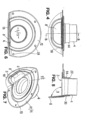
- a drain body 1, referred to as the "first”, is shown, which consists of a pipe socket 4 and a partially annular flange body 2.
- a round recess 3 is arranged on the flange body 2, which is slightly larger than the inside diameter of the pipe socket 4.
- the flange body 2 merges via a bending edge 6 tangent to the recess 3 into a flange section 8 bent at an obtuse angle ⁇ , as is particularly clearly shown in Fig. 3 can be seen.
- the angle ⁇ measured between the flange section 8 and a plane E defined by the partially annular flange body 2, is 92 0 .
- a second drain body 11 can be removed, comprising a second pipe socket 14 and a second partially annular flange body 12 with a recess 13, which merges via a bending edge 26 into a flange section 18 bent at almost the same angle ⁇ .
- the flange section 8 has an angle ⁇ that is 2° to 3° larger than the flange section 18, which ensures a stronger compression of the sealing element 7.
- the flange section 8 when pressed, is flush with the complementary recess of the flange section 18, thus ensuring barrier-free drainage of the roof area to be drained.
- the flange section 18 is preferably installed in a recess of the waterproofing membrane running beneath the flange section 18.
- the second pipe socket 14 has an inner diameter D2 that is not less than the outer diameter D1 of the first pipe socket 4, so that the pipe sockets 4; 14 can be pushed into each other.
- the second pipe socket 14 is shorter than the first; after pushing them together (see Figures 4 and 5 ), the inner pipe socket 4 protrudes beyond a free end 22 of the pipe socket 14. This in turn allows the sliding on of a drain pipe 5 (cf. Fig. 8 ) on the inner pipe socket 4 to the said end 22 of the pipe socket 14.
- the drain pipe 5 is inserted between the two pipe sockets 4; 14 and glued there.
- circumferential locking ring elements 15 made of hard plastic are inserted, the tips of which (not shown) point outwards. Accordingly, complementary counter-locking elements are arranged on an inner side 17 of the shorter pipe socket 14.
- the counter-locking elements are designed as partial locking ring elements 16, in other words as sections of the locking ring elements distributed around the circumference of the inner side 17 (cf. Figures 2 and 3 ) is executed.
- Reference number "7” denotes a sealing element, indicated by a dashed line, with a recess 23 matching the outer diameter of the pipe socket 4.
- the sealing element 7 is made in the form of a flexible, 4 mm thick, circular elastomer sleeve.
- circumferential sealing ribs 19 are incorporated on both flange bodies 2, 12, which engage with the softer material of the intermediate elastomer sleeve during the subsequent pressing of the two drain bodies 1; 11 together.
- FIG. 9 An angle drain 100 composed of the drain bodies 1; 11 and a sealing element 7 flanged between them is shown in Fig. 9 shown. Increased stability and tightness are ensured not only by the interlocking locking ring elements 15 and 16 (cf. Figures 1 to 3 ), which compress the sealing element 7 on both sides, but also the sealing ribs 9, 19 (cf. Figures 3 and 7 ) and last but not least a permanent bonding of the sealing element 7 at least with the smaller flange body 2.
- a parapet (enclosure 20) with a slightly outwardly inclined through opening 24 projects over a flat roof sealing level 25, in whose inlet area 27 the angled drain 100 with its two pipe sockets 4, 14 is installed and fastened to the enclosure 20 and the flat roof by means of screws (not shown).
- the screws are screwed in via peripheral openings 28 (screw head receptacles) distributed on the flange body 12.
- the drain pipe 5 inserted through the through opening 24 forms an angle ⁇ of approximately 92 ° with the flange body 2; 12.
- a barrier-free angle drain 100 is created which is characterized by increased, permanent stability and tightness, the locking connection 30 of which has an irreversible toothing and tensioning area 21 (cf. Figures 8 and 9 ) of the sealing element 7.
Landscapes
- Engineering & Computer Science (AREA)
- Architecture (AREA)
- Civil Engineering (AREA)
- Structural Engineering (AREA)
- Gasket Seals (AREA)
Applications Claiming Priority (1)
| Application Number | Priority Date | Filing Date | Title |
|---|---|---|---|
| DE202021105918.4U DE202021105918U1 (de) | 2021-10-28 | 2021-10-28 | Winkelablauf für Flachdächer mit einer über die Dachfläche ragenden Umfassung |
Publications (2)
| Publication Number | Publication Date |
|---|---|
| EP4174245A1 EP4174245A1 (de) | 2023-05-03 |
| EP4174245B1 true EP4174245B1 (de) | 2025-03-19 |
Family
ID=78827347
Family Applications (1)
| Application Number | Title | Priority Date | Filing Date |
|---|---|---|---|
| EP22000239.8A Active EP4174245B1 (de) | 2021-10-28 | 2022-10-27 | Winkelablauf für flachdächer mit einer über die dachfläche ragenden umfassung |
Country Status (5)
| Country | Link |
|---|---|
| EP (1) | EP4174245B1 (da) |
| DE (1) | DE202021105918U1 (da) |
| DK (1) | DK4174245T3 (da) |
| HU (1) | HUE071791T2 (da) |
| PL (1) | PL4174245T3 (da) |
Citations (1)
| Publication number | Priority date | Publication date | Assignee | Title |
|---|---|---|---|---|
| DE29905121U1 (de) * | 1999-03-22 | 2000-08-10 | Vahlbrauk, Wolfgang, Dipl.-Ing., 37581 Bad Gandersheim | Wasserablaufvorrichtung |
Family Cites Families (6)
| Publication number | Priority date | Publication date | Assignee | Title |
|---|---|---|---|---|
| JPH0676724B2 (ja) * | 1989-12-06 | 1994-09-28 | ドーエイ外装有限会社 | ドレンの取付け方法およびドレン |
| NL9202258A (nl) * | 1992-12-24 | 1994-07-18 | Ubbink Nederland Bv | Stadsuitloop. |
| US5615526A (en) * | 1995-05-08 | 1997-04-01 | Palmer; Dale W. | Drains for single layer synthetic roofing and waterproofing membranes |
| DE19840593B4 (de) * | 1998-09-05 | 2004-02-19 | Oskar Fleck | Vorrichtung zur Herstellung einer Flachdach-Entwässerung |
| DE20002607U1 (de) | 2000-02-15 | 2000-04-06 | Fleck, Oskar, 45711 Datteln | Attikaabfluß |
| PL3597834T3 (pl) | 2018-07-20 | 2022-01-24 | Dallmer Gmbh & Co. Kg | Element konstrukcyjny do urządzenia odpływowego dla dachu płaskiego z attyką |
-
2021
- 2021-10-28 DE DE202021105918.4U patent/DE202021105918U1/de active Active
-
2022
- 2022-10-27 PL PL22000239.8T patent/PL4174245T3/pl unknown
- 2022-10-27 EP EP22000239.8A patent/EP4174245B1/de active Active
- 2022-10-27 DK DK22000239.8T patent/DK4174245T3/da active
- 2022-10-27 HU HUE22000239A patent/HUE071791T2/hu unknown
Patent Citations (1)
| Publication number | Priority date | Publication date | Assignee | Title |
|---|---|---|---|---|
| DE29905121U1 (de) * | 1999-03-22 | 2000-08-10 | Vahlbrauk, Wolfgang, Dipl.-Ing., 37581 Bad Gandersheim | Wasserablaufvorrichtung |
Also Published As
| Publication number | Publication date |
|---|---|
| DK4174245T3 (da) | 2025-06-10 |
| PL4174245T3 (pl) | 2025-07-21 |
| EP4174245A1 (de) | 2023-05-03 |
| DE202021105918U1 (de) | 2021-11-18 |
| HUE071791T2 (hu) | 2025-09-28 |
Similar Documents
| Publication | Publication Date | Title |
|---|---|---|
| DE69003111T2 (de) | Zweiteiliger kunststoffaufsatz zur reparatur oder renovierung einer kanalisationsabzweigestelle und mit dem aufsatz reparierte oder renovierte kanalisation. | |
| EP2054558B1 (de) | Entwässerungsvorrichtung | |
| DE69521743T2 (de) | Vorrichtung zum Abdichten eines ringförmigen Raums | |
| DE102010056448B3 (de) | Rohrverbindungsanordnung | |
| DE2022287A1 (de) | Rohrverbindung | |
| DE102019110322A1 (de) | Ablaufvorrichtung mit einem Adapter zum Anschluss an eine Rohrleitung | |
| EP0125382A1 (de) | Teil-Sickerrohr mit Steck-Muffe | |
| DE2831029A1 (de) | Gehaeuse zum schutz der verbindungsstelle von langgestreckten gegenstaenden, insbesondere zum schutz eines kabelspleisses | |
| EP0317903B1 (de) | Dichtring | |
| DE19610477A1 (de) | Aufweitbare Schale zur innenseitigen Kanalrohrsanierung | |
| DE2911575A1 (de) | Zugfeste rohrkupplung | |
| DE2422658B1 (de) | Wassereinlauf zur Entwässerung von Flachdächern, Baikonen, Terrassen od. dgl | |
| DE102009048246A1 (de) | Versprungbogen | |
| EP4174245B1 (de) | Winkelablauf für flachdächer mit einer über die dachfläche ragenden umfassung | |
| EP0759135B1 (de) | Sanierungselement für kanäle, drainage-deponierrohre und dgl. | |
| DE4003906C2 (de) | Vorrichtung zum Durchführen eines Rohres durch eine biegsame Dachdichtungsbahn | |
| DE19741665A1 (de) | Element und Verfahren zur Sanierung von runden Abwasserrohren von 150 bis 600 mm Durchmesser | |
| DE69121548T2 (de) | Verbesserte Bandschelle mit keilförmigen, geschlitzten Nocken | |
| DE3301229C2 (da) | ||
| DE20015281U1 (de) | Einfassung für eine Abdichtungsbahn | |
| DE3146275C2 (de) | Bodenablauf | |
| DE29601453U1 (de) | Anschlußelement für ein Zuleitungsrohr | |
| DE4009403C2 (de) | Rohrleitungskupplung | |
| AT1847U1 (de) | Schutzhülse für eine verbindung zwischen einem flexiblen rohr und einer anschlussarmatur oder einem fitting | |
| DE102017112934A1 (de) | Dichtrinnenanordnung |
Legal Events
| Date | Code | Title | Description |
|---|---|---|---|
| PUAI | Public reference made under article 153(3) epc to a published international application that has entered the european phase |
Free format text: ORIGINAL CODE: 0009012 |
|
| STAA | Information on the status of an ep patent application or granted ep patent |
Free format text: STATUS: THE APPLICATION HAS BEEN PUBLISHED |
|
| AK | Designated contracting states |
Kind code of ref document: A1 Designated state(s): AL AT BE BG CH CY CZ DE DK EE ES FI FR GB GR HR HU IE IS IT LI LT LU LV MC ME MK MT NL NO PL PT RO RS SE SI SK SM TR |
|
| STAA | Information on the status of an ep patent application or granted ep patent |
Free format text: STATUS: REQUEST FOR EXAMINATION WAS MADE |
|
| 17P | Request for examination filed |
Effective date: 20230516 |
|
| RBV | Designated contracting states (corrected) |
Designated state(s): AL AT BE BG CH CY CZ DE DK EE ES FI FR GB GR HR HU IE IS IT LI LT LU LV MC ME MK MT NL NO PL PT RO RS SE SI SK SM TR |
|
| RAX | Requested extension states of the european patent have changed |
Extension state: BA Payment date: 20231117 |
|
| GRAP | Despatch of communication of intention to grant a patent |
Free format text: ORIGINAL CODE: EPIDOSNIGR1 |
|
| STAA | Information on the status of an ep patent application or granted ep patent |
Free format text: STATUS: GRANT OF PATENT IS INTENDED |
|
| INTG | Intention to grant announced |
Effective date: 20240613 |
|
| GRAS | Grant fee paid |
Free format text: ORIGINAL CODE: EPIDOSNIGR3 |
|
| GRAA | (expected) grant |
Free format text: ORIGINAL CODE: 0009210 |
|
| STAA | Information on the status of an ep patent application or granted ep patent |
Free format text: STATUS: THE PATENT HAS BEEN GRANTED |
|
| AK | Designated contracting states |
Kind code of ref document: B1 Designated state(s): AL AT BE BG CH CY CZ DE DK EE ES FI FR GB GR HR HU IE IS IT LI LT LU LV MC ME MK MT NL NO PL PT RO RS SE SI SK SM TR |
|
| REG | Reference to a national code |
Ref country code: GB Ref legal event code: FG4D Free format text: NOT ENGLISH |
|
| REG | Reference to a national code |
Ref country code: CH Ref legal event code: EP |
|
| REG | Reference to a national code |
Ref country code: IE Ref legal event code: FG4D Free format text: LANGUAGE OF EP DOCUMENT: GERMAN |
|
| REG | Reference to a national code |
Ref country code: DE Ref legal event code: R096 Ref document number: 502022003215 Country of ref document: DE |
|
| REG | Reference to a national code |
Ref country code: DK Ref legal event code: T3 Effective date: 20250606 |
|
| REG | Reference to a national code |
Ref country code: NL Ref legal event code: FP |
|
| PG25 | Lapsed in a contracting state [announced via postgrant information from national office to epo] |
Ref country code: RS Free format text: LAPSE BECAUSE OF FAILURE TO SUBMIT A TRANSLATION OF THE DESCRIPTION OR TO PAY THE FEE WITHIN THE PRESCRIBED TIME-LIMIT Effective date: 20250619 |
|
| PG25 | Lapsed in a contracting state [announced via postgrant information from national office to epo] |
Ref country code: FI Free format text: LAPSE BECAUSE OF FAILURE TO SUBMIT A TRANSLATION OF THE DESCRIPTION OR TO PAY THE FEE WITHIN THE PRESCRIBED TIME-LIMIT Effective date: 20250319 |
|
| REG | Reference to a national code |
Ref country code: LT Ref legal event code: MG9D |
|
| PG25 | Lapsed in a contracting state [announced via postgrant information from national office to epo] |
Ref country code: NO Free format text: LAPSE BECAUSE OF FAILURE TO SUBMIT A TRANSLATION OF THE DESCRIPTION OR TO PAY THE FEE WITHIN THE PRESCRIBED TIME-LIMIT Effective date: 20250619 |
|
| PG25 | Lapsed in a contracting state [announced via postgrant information from national office to epo] |
Ref country code: HR Free format text: LAPSE BECAUSE OF FAILURE TO SUBMIT A TRANSLATION OF THE DESCRIPTION OR TO PAY THE FEE WITHIN THE PRESCRIBED TIME-LIMIT Effective date: 20250319 |
|
| PG25 | Lapsed in a contracting state [announced via postgrant information from national office to epo] |
Ref country code: LV Free format text: LAPSE BECAUSE OF FAILURE TO SUBMIT A TRANSLATION OF THE DESCRIPTION OR TO PAY THE FEE WITHIN THE PRESCRIBED TIME-LIMIT Effective date: 20250319 |
|
| PG25 | Lapsed in a contracting state [announced via postgrant information from national office to epo] |
Ref country code: BG Free format text: LAPSE BECAUSE OF FAILURE TO SUBMIT A TRANSLATION OF THE DESCRIPTION OR TO PAY THE FEE WITHIN THE PRESCRIBED TIME-LIMIT Effective date: 20250319 Ref country code: GR Free format text: LAPSE BECAUSE OF FAILURE TO SUBMIT A TRANSLATION OF THE DESCRIPTION OR TO PAY THE FEE WITHIN THE PRESCRIBED TIME-LIMIT Effective date: 20250620 |
|
| REG | Reference to a national code |
Ref country code: SK Ref legal event code: T3 Ref document number: E 46501 Country of ref document: SK |
|
| PG25 | Lapsed in a contracting state [announced via postgrant information from national office to epo] |
Ref country code: SE Free format text: LAPSE BECAUSE OF FAILURE TO SUBMIT A TRANSLATION OF THE DESCRIPTION OR TO PAY THE FEE WITHIN THE PRESCRIBED TIME-LIMIT Effective date: 20250319 |
|
| REG | Reference to a national code |
Ref country code: HU Ref legal event code: AG4A Ref document number: E071791 Country of ref document: HU |
|
| PG25 | Lapsed in a contracting state [announced via postgrant information from national office to epo] |
Ref country code: SM Free format text: LAPSE BECAUSE OF FAILURE TO SUBMIT A TRANSLATION OF THE DESCRIPTION OR TO PAY THE FEE WITHIN THE PRESCRIBED TIME-LIMIT Effective date: 20250319 |
|
| PG25 | Lapsed in a contracting state [announced via postgrant information from national office to epo] |
Ref country code: ES Free format text: LAPSE BECAUSE OF FAILURE TO SUBMIT A TRANSLATION OF THE DESCRIPTION OR TO PAY THE FEE WITHIN THE PRESCRIBED TIME-LIMIT Effective date: 20250319 Ref country code: PT Free format text: LAPSE BECAUSE OF FAILURE TO SUBMIT A TRANSLATION OF THE DESCRIPTION OR TO PAY THE FEE WITHIN THE PRESCRIBED TIME-LIMIT Effective date: 20250721 |
|
| PG25 | Lapsed in a contracting state [announced via postgrant information from national office to epo] |
Ref country code: IT Free format text: LAPSE BECAUSE OF FAILURE TO SUBMIT A TRANSLATION OF THE DESCRIPTION OR TO PAY THE FEE WITHIN THE PRESCRIBED TIME-LIMIT Effective date: 20250319 |
|
| PG25 | Lapsed in a contracting state [announced via postgrant information from national office to epo] |
Ref country code: EE Free format text: LAPSE BECAUSE OF FAILURE TO SUBMIT A TRANSLATION OF THE DESCRIPTION OR TO PAY THE FEE WITHIN THE PRESCRIBED TIME-LIMIT Effective date: 20250319 |
|
| PG25 | Lapsed in a contracting state [announced via postgrant information from national office to epo] |
Ref country code: RO Free format text: LAPSE BECAUSE OF FAILURE TO SUBMIT A TRANSLATION OF THE DESCRIPTION OR TO PAY THE FEE WITHIN THE PRESCRIBED TIME-LIMIT Effective date: 20250319 |
|
| PG25 | Lapsed in a contracting state [announced via postgrant information from national office to epo] |
Ref country code: IS Free format text: LAPSE BECAUSE OF FAILURE TO SUBMIT A TRANSLATION OF THE DESCRIPTION OR TO PAY THE FEE WITHIN THE PRESCRIBED TIME-LIMIT Effective date: 20250719 |
|
| REG | Reference to a national code |
Ref country code: CH Ref legal event code: U11 Free format text: ST27 STATUS EVENT CODE: U-0-0-U10-U11 (AS PROVIDED BY THE NATIONAL OFFICE) Effective date: 20251101 |
|
| PGFP | Annual fee paid to national office [announced via postgrant information from national office to epo] |
Ref country code: HU Payment date: 20251027 Year of fee payment: 4 |
|
| PGFP | Annual fee paid to national office [announced via postgrant information from national office to epo] |
Ref country code: LU Payment date: 20251022 Year of fee payment: 4 Ref country code: NL Payment date: 20251021 Year of fee payment: 4 |
|
| REG | Reference to a national code |
Ref country code: DE Ref legal event code: R097 Ref document number: 502022003215 Country of ref document: DE |
|
| PGFP | Annual fee paid to national office [announced via postgrant information from national office to epo] |
Ref country code: DE Payment date: 20250716 Year of fee payment: 4 |
|
| PGFP | Annual fee paid to national office [announced via postgrant information from national office to epo] |
Ref country code: AT Payment date: 20260113 Year of fee payment: 4 |
|
| PGFP | Annual fee paid to national office [announced via postgrant information from national office to epo] |
Ref country code: DK Payment date: 20251027 Year of fee payment: 4 |
|
| PGFP | Annual fee paid to national office [announced via postgrant information from national office to epo] |
Ref country code: FR Payment date: 20251030 Year of fee payment: 4 |
|
| PGFP | Annual fee paid to national office [announced via postgrant information from national office to epo] |
Ref country code: BE Payment date: 20251021 Year of fee payment: 4 |
|
| PGFP | Annual fee paid to national office [announced via postgrant information from national office to epo] |
Ref country code: CH Payment date: 20251101 Year of fee payment: 4 |
|
| PGFP | Annual fee paid to national office [announced via postgrant information from national office to epo] |
Ref country code: CZ Payment date: 20251021 Year of fee payment: 4 |
|
| PGFP | Annual fee paid to national office [announced via postgrant information from national office to epo] |
Ref country code: PL Payment date: 20251016 Year of fee payment: 4 |
|
| PLBE | No opposition filed within time limit |
Free format text: ORIGINAL CODE: 0009261 |
|
| STAA | Information on the status of an ep patent application or granted ep patent |
Free format text: STATUS: NO OPPOSITION FILED WITHIN TIME LIMIT |
|
| PGFP | Annual fee paid to national office [announced via postgrant information from national office to epo] |
Ref country code: SK Payment date: 20251020 Year of fee payment: 4 |
|
| REG | Reference to a national code |
Ref country code: CH Ref legal event code: L10 Free format text: ST27 STATUS EVENT CODE: U-0-0-L10-L00 (AS PROVIDED BY THE NATIONAL OFFICE) Effective date: 20260128 |
|
| 26N | No opposition filed |
Effective date: 20251222 |