EP4174318A1 - Compresseur rotatif et dispositif à cycle de réfrigération - Google Patents
Compresseur rotatif et dispositif à cycle de réfrigération Download PDFInfo
- Publication number
- EP4174318A1 EP4174318A1 EP21834557.7A EP21834557A EP4174318A1 EP 4174318 A1 EP4174318 A1 EP 4174318A1 EP 21834557 A EP21834557 A EP 21834557A EP 4174318 A1 EP4174318 A1 EP 4174318A1
- Authority
- EP
- European Patent Office
- Prior art keywords
- intake
- piston
- cylinder
- rotary compressor
- vane
- Prior art date
- Legal status (The legal status is an assumption and is not a legal conclusion. Google has not performed a legal analysis and makes no representation as to the accuracy of the status listed.)
- Withdrawn
Links
- 238000005057 refrigeration Methods 0.000 title claims abstract description 15
- 230000006835 compression Effects 0.000 claims abstract description 52
- 238000007906 compression Methods 0.000 claims abstract description 52
- 238000005192 partition Methods 0.000 claims abstract description 20
- CURLTUGMZLYLDI-UHFFFAOYSA-N Carbon dioxide Chemical compound O=C=O CURLTUGMZLYLDI-UHFFFAOYSA-N 0.000 claims description 16
- 239000012530 fluid Substances 0.000 claims description 11
- 229910002092 carbon dioxide Inorganic materials 0.000 claims description 8
- 239000001569 carbon dioxide Substances 0.000 claims description 8
- XLYOFNOQVPJJNP-UHFFFAOYSA-N water Substances O XLYOFNOQVPJJNP-UHFFFAOYSA-N 0.000 claims description 5
- 239000007789 gas Substances 0.000 description 30
- 239000003507 refrigerant Substances 0.000 description 13
- 238000004891 communication Methods 0.000 description 9
- 238000000034 method Methods 0.000 description 7
- 230000000694 effects Effects 0.000 description 6
- 238000005096 rolling process Methods 0.000 description 6
- 239000007788 liquid Substances 0.000 description 4
- 230000009191 jumping Effects 0.000 description 3
- 239000003990 capacitor Substances 0.000 description 2
- 238000010586 diagram Methods 0.000 description 2
- 230000008014 freezing Effects 0.000 description 2
- 238000007710 freezing Methods 0.000 description 2
- 230000006870 function Effects 0.000 description 2
- 238000003825 pressing Methods 0.000 description 2
- 239000000470 constituent Substances 0.000 description 1
- 230000006866 deterioration Effects 0.000 description 1
- 230000005484 gravity Effects 0.000 description 1
- 238000003780 insertion Methods 0.000 description 1
- 230000037431 insertion Effects 0.000 description 1
- 238000004519 manufacturing process Methods 0.000 description 1
- 239000000463 material Substances 0.000 description 1
- 239000000203 mixture Substances 0.000 description 1
- 230000001151 other effect Effects 0.000 description 1
- 230000008447 perception Effects 0.000 description 1
- 238000003466 welding Methods 0.000 description 1
Images



Classifications
-
- F—MECHANICAL ENGINEERING; LIGHTING; HEATING; WEAPONS; BLASTING
- F04—POSITIVE - DISPLACEMENT MACHINES FOR LIQUIDS; PUMPS FOR LIQUIDS OR ELASTIC FLUIDS
- F04C—ROTARY-PISTON, OR OSCILLATING-PISTON, POSITIVE-DISPLACEMENT MACHINES FOR LIQUIDS; ROTARY-PISTON, OR OSCILLATING-PISTON, POSITIVE-DISPLACEMENT PUMPS
- F04C18/00—Rotary-piston pumps specially adapted for elastic fluids
- F04C18/30—Rotary-piston pumps specially adapted for elastic fluids having the characteristics covered by two or more of groups F04C18/02, F04C18/08, F04C18/22, F04C18/24, F04C18/48, or having the characteristics covered by one of these groups together with some other type of movement between co-operating members
- F04C18/34—Rotary-piston pumps specially adapted for elastic fluids having the characteristics covered by two or more of groups F04C18/02, F04C18/08, F04C18/22, F04C18/24, F04C18/48, or having the characteristics covered by one of these groups together with some other type of movement between co-operating members having the movement defined in group F04C18/08 or F04C18/22 and relative reciprocation between the co-operating members
- F04C18/356—Rotary-piston pumps specially adapted for elastic fluids having the characteristics covered by two or more of groups F04C18/02, F04C18/08, F04C18/22, F04C18/24, F04C18/48, or having the characteristics covered by one of these groups together with some other type of movement between co-operating members having the movement defined in group F04C18/08 or F04C18/22 and relative reciprocation between the co-operating members with vanes reciprocating with respect to the outer member
-
- F—MECHANICAL ENGINEERING; LIGHTING; HEATING; WEAPONS; BLASTING
- F01—MACHINES OR ENGINES IN GENERAL; ENGINE PLANTS IN GENERAL; STEAM ENGINES
- F01C—ROTARY-PISTON OR OSCILLATING-PISTON MACHINES OR ENGINES
- F01C21/00—Component parts, details or accessories not provided for in groups F01C1/00 - F01C20/00
- F01C21/10—Outer members for co-operation with rotary pistons; Casings
- F01C21/104—Stators; Members defining the outer boundaries of the working chamber
- F01C21/108—Stators; Members defining the outer boundaries of the working chamber with an axial surface, e.g. side plates
-
- F—MECHANICAL ENGINEERING; LIGHTING; HEATING; WEAPONS; BLASTING
- F04—POSITIVE - DISPLACEMENT MACHINES FOR LIQUIDS; PUMPS FOR LIQUIDS OR ELASTIC FLUIDS
- F04C—ROTARY-PISTON, OR OSCILLATING-PISTON, POSITIVE-DISPLACEMENT MACHINES FOR LIQUIDS; ROTARY-PISTON, OR OSCILLATING-PISTON, POSITIVE-DISPLACEMENT PUMPS
- F04C29/00—Component parts, details or accessories of pumps or pumping installations, not provided for in groups F04C18/00 - F04C28/00
- F04C29/12—Arrangements for admission or discharge of the working fluid, e.g. constructional features of the inlet or outlet
-
- F—MECHANICAL ENGINEERING; LIGHTING; HEATING; WEAPONS; BLASTING
- F04—POSITIVE - DISPLACEMENT MACHINES FOR LIQUIDS; PUMPS FOR LIQUIDS OR ELASTIC FLUIDS
- F04C—ROTARY-PISTON, OR OSCILLATING-PISTON, POSITIVE-DISPLACEMENT MACHINES FOR LIQUIDS; ROTARY-PISTON, OR OSCILLATING-PISTON, POSITIVE-DISPLACEMENT PUMPS
- F04C2240/00—Components
- F04C2240/80—Other components
- F04C2240/806—Pipes for fluids; Fittings therefor
Definitions
- Patent document 1 discloses a rotary compressor which reliably prevents a vane from jumping.
- This rotary compressor includes a cylinder whose both end openings are closed, a piston which rotates in the cylinder, a vane which forms a compression space together with the piston and the cylinder and which partitions the space into a high pressure side and a low pressure side, and connecting means for swingably connecting the piston and the vane to each other.
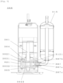
- the rotary compressor 200 includes a drive shaft 201, the upper piston 2021, the lower piston 2022, the upper cylinder 2031, the lower cylinder 2032, an upper bearing 204, a lower bearing 205, upper and lower vanes, the upper intake hole 2071a, the lower intake hole 2072a and a partition plate 221.
- Upper and lower compression elements are configured in the axial direction.
- the partition plate 221 is provided between the upper and lower compression elements.
- An upper bearing 204 and the lower bearing 205 support the drive shaft 201.
- the upper intake hole 2071a is provided in the upper bearing 204
- the lower intake hole 2072a is provided in the lower bearing 205.
- a rotary compressor 300 of the third embodiment is different from the rotary compressor 200 of the second embodiment at least in that a partition plate 321 is provided with an intake hole 307a instead of an upper bearing 304 and a lower bearing 305.
- the rotary compressor 100 of one cylinder and the rotary compressors 200 and 300 of two cylinders are described as one examples of the rotary compressor. It is only necessary that the rotary compressor compresses gas. Therefore, the rotary compressor is not limited to the rotary compressor 100 of one cylinder or the rotary compressors 200 and 300 of two cylinders. However, if the rotary compressor 100 of one cylinder or the rotary compressors 200 and 300 of two cylinders are used, there are merits that balance between costs, efficiency and reliability is kept and volume production can be made. As the rotary compressor, a two-stage compressor may be used.
- one cylinder may include a plurality of vanes and compression chambers. If this is used, torque variation can be reduced by carrying out the compression action which is substantially the same as that of the two-cylinder type in the configuration of the rotary compressor 100 of the one cylinder, and a pressure difference can be reduced if the two-stage compression configuration is employed. Therefore it is possible to realize a rotary compressor capable of carrying out low vibration and high pressure ratio operation with the small number of parts.
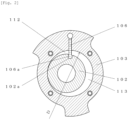
- vane 106 having the engaging portion 106a which is swingably fitted into and connected to the engaging groove 102a formed in the piston 102 was described as one example of the vane.
- the vane partitions the intake chamber and the compression chamber from each other, the vane is always operated integrally with the piston, and a spring is unnecessary on the back surface of the vane. Therefore, the vane is not limited to the vane 106 including the engaging portion 106a which is swingably fitted into and connected to the engaging groove 102a formed in the piston 102.
Landscapes
- Engineering & Computer Science (AREA)
- Mechanical Engineering (AREA)
- General Engineering & Computer Science (AREA)
- Applications Or Details Of Rotary Compressors (AREA)
Applications Claiming Priority (2)
| Application Number | Priority Date | Filing Date | Title |
|---|---|---|---|
| JP2020111037 | 2020-06-29 | ||
| PCT/JP2021/001772 WO2022004028A1 (fr) | 2020-06-29 | 2021-01-20 | Compresseur rotatif et dispositif à cycle de réfrigération |
Publications (2)
| Publication Number | Publication Date |
|---|---|
| EP4174318A1 true EP4174318A1 (fr) | 2023-05-03 |
| EP4174318A4 EP4174318A4 (fr) | 2023-12-13 |
Family
ID=79315186
Family Applications (1)
| Application Number | Title | Priority Date | Filing Date |
|---|---|---|---|
| EP21834557.7A Withdrawn EP4174318A4 (fr) | 2020-06-29 | 2021-01-20 | Compresseur rotatif et dispositif à cycle de réfrigération |
Country Status (4)
| Country | Link |
|---|---|
| EP (1) | EP4174318A4 (fr) |
| JP (1) | JP7678527B2 (fr) |
| CN (1) | CN115190944A (fr) |
| WO (1) | WO2022004028A1 (fr) |
Families Citing this family (3)
| Publication number | Priority date | Publication date | Assignee | Title |
|---|---|---|---|---|
| JP2023005307A (ja) * | 2021-06-28 | 2023-01-18 | パナソニックIpマネジメント株式会社 | 圧縮機 |
| CN118959322A (zh) * | 2024-08-01 | 2024-11-15 | 珠海凌达压缩机有限公司 | 一种基于法兰进气的压缩机 |
| CN119712551A (zh) * | 2024-12-20 | 2025-03-28 | 珠海凌达压缩机有限公司 | 一种压缩机泵体结构、压缩机和空调器 |
Family Cites Families (12)
| Publication number | Priority date | Publication date | Assignee | Title |
|---|---|---|---|---|
| JPH0381592A (ja) * | 1989-08-24 | 1991-04-05 | Mitsubishi Electric Corp | 2気筒回転式圧縮機 |
| JPH09250477A (ja) * | 1996-03-18 | 1997-09-22 | Toshiba Corp | ロータリコンプレッサ |
| JP2000120572A (ja) | 1998-10-12 | 2000-04-25 | Sanyo Electric Co Ltd | 回転式圧縮機 |
| US20070269328A1 (en) * | 2003-05-19 | 2007-11-22 | Hiroshi Hasegawa | Antennas Array Calibration Arrangement and Method |
| JP4289975B2 (ja) * | 2003-11-05 | 2009-07-01 | 三洋電機株式会社 | 多段圧縮式ロータリ圧縮機 |
| JP2006207532A (ja) * | 2005-01-31 | 2006-08-10 | Sanyo Electric Co Ltd | ロータリコンプレッサ |
| JP5070097B2 (ja) * | 2007-08-28 | 2012-11-07 | 東芝キヤリア株式会社 | 2シリンダ回転式圧縮機およびこれを用いた冷凍サイクル装置 |
| KR101442550B1 (ko) * | 2008-08-06 | 2014-09-22 | 엘지전자 주식회사 | 로터리 압축기 |
| JP5040934B2 (ja) * | 2009-01-22 | 2012-10-03 | パナソニック株式会社 | 密閉型圧縮機 |
| JP2010255624A (ja) * | 2009-03-31 | 2010-11-11 | Panasonic Corp | ロータリ圧縮機 |
| EP2547969A1 (fr) * | 2010-03-17 | 2013-01-23 | Panasonic Corporation | Appareil à cycle de réfrigération |
| JP5824664B2 (ja) * | 2010-11-17 | 2015-11-25 | パナソニックIpマネジメント株式会社 | ロータリ圧縮機及び冷凍サイクル装置 |
-
2021
- 2021-01-20 WO PCT/JP2021/001772 patent/WO2022004028A1/fr not_active Ceased
- 2021-01-20 CN CN202180017156.9A patent/CN115190944A/zh active Pending
- 2021-01-20 JP JP2022533665A patent/JP7678527B2/ja active Active
- 2021-01-20 EP EP21834557.7A patent/EP4174318A4/fr not_active Withdrawn
Also Published As
| Publication number | Publication date |
|---|---|
| WO2022004028A1 (fr) | 2022-01-06 |
| JPWO2022004028A1 (fr) | 2022-01-06 |
| JP7678527B2 (ja) | 2025-05-16 |
| CN115190944A (zh) | 2022-10-14 |
| EP4174318A4 (fr) | 2023-12-13 |
Similar Documents
| Publication | Publication Date | Title |
|---|---|---|
| US6264446B1 (en) | Horizontal scroll compressor | |
| JP3024706B2 (ja) | 回転圧縮器 | |
| AU2005236313B2 (en) | Rotary fluid machine | |
| US9004888B2 (en) | Rotary compressor having discharge groove to communicate compression chamber with discharge port near vane groove | |
| JPH11241682A (ja) | Co2用圧縮機 | |
| JP2008240667A (ja) | ロータリ圧縮機 | |
| US8888475B2 (en) | Scroll compressor with oil supply across a sealing part | |
| KR101510697B1 (ko) | 회전축 및 이를 적용한 밀폐형 압축기 및 이를 적용한 냉동기기 | |
| US9689388B2 (en) | Scroll compressor | |
| JP7678527B2 (ja) | ロータリ圧縮機および冷凍サイクル装置 | |
| CN110925211B (zh) | 一种低背压滚动转子式压缩机及空调 | |
| JP2007315261A (ja) | 密閉型圧縮機 | |
| WO2022239675A1 (fr) | Compresseur rotatif et dispositif à cycle de réfrigération | |
| JP3838186B2 (ja) | 2段圧縮機 | |
| JP4470914B2 (ja) | 2段圧縮機 | |
| CA2636093C (fr) | Compresseur rotatif a deux etages | |
| JP5276332B2 (ja) | 密閉型圧縮機 | |
| KR200392423Y1 (ko) | 복식 로터리 압축기의 실링구조 | |
| US11933305B2 (en) | Rotary compressor with an oil groove facing the vane and exposed to a gap between the vane and the piston | |
| CN118749045A (zh) | 旋转式压缩机 | |
| JP4830708B2 (ja) | 圧縮機 | |
| JP2013174180A (ja) | スクロール圧縮機 | |
| JP2010223140A (ja) | 2段圧縮ロータリ圧縮機 | |
| KR20100081812A (ko) | 스크롤 압축기 및 이를 적용한 냉동기기 | |
| JP3370041B2 (ja) | 回転圧縮機 |
Legal Events
| Date | Code | Title | Description |
|---|---|---|---|
| STAA | Information on the status of an ep patent application or granted ep patent |
Free format text: STATUS: THE INTERNATIONAL PUBLICATION HAS BEEN MADE |
|
| PUAI | Public reference made under article 153(3) epc to a published international application that has entered the european phase |
Free format text: ORIGINAL CODE: 0009012 |
|
| STAA | Information on the status of an ep patent application or granted ep patent |
Free format text: STATUS: REQUEST FOR EXAMINATION WAS MADE |
|
| 17P | Request for examination filed |
Effective date: 20230130 |
|
| AK | Designated contracting states |
Kind code of ref document: A1 Designated state(s): AL AT BE BG CH CY CZ DE DK EE ES FI FR GB GR HR HU IE IS IT LI LT LU LV MC MK MT NL NO PL PT RO RS SE SI SK SM TR |
|
| DAV | Request for validation of the european patent (deleted) | ||
| DAX | Request for extension of the european patent (deleted) | ||
| A4 | Supplementary search report drawn up and despatched |
Effective date: 20231109 |
|
| RIC1 | Information provided on ipc code assigned before grant |
Ipc: F01C 21/10 20060101ALI20231103BHEP Ipc: F04C 29/12 20060101ALI20231103BHEP Ipc: F04C 18/356 20060101ALI20231103BHEP Ipc: F04C 18/324 20060101ALI20231103BHEP Ipc: F04C 29/00 20060101AFI20231103BHEP |
|
| STAA | Information on the status of an ep patent application or granted ep patent |
Free format text: STATUS: THE APPLICATION IS DEEMED TO BE WITHDRAWN |
|
| 18D | Application deemed to be withdrawn |
Effective date: 20240529 |