EP4174893A1 - Drehschalter - Google Patents
Drehschalter Download PDFInfo
- Publication number
- EP4174893A1 EP4174893A1 EP21845663.0A EP21845663A EP4174893A1 EP 4174893 A1 EP4174893 A1 EP 4174893A1 EP 21845663 A EP21845663 A EP 21845663A EP 4174893 A1 EP4174893 A1 EP 4174893A1
- Authority
- EP
- European Patent Office
- Prior art keywords
- energy storage
- component
- pawl
- disposed
- latch
- Prior art date
- Legal status (The legal status is an assumption and is not a legal conclusion. Google has not performed a legal analysis and makes no representation as to the accuracy of the status listed.)
- Granted
Links
Images






Classifications
-
- H—ELECTRICITY
- H01—ELECTRIC ELEMENTS
- H01H—ELECTRIC SWITCHES; RELAYS; SELECTORS; EMERGENCY PROTECTIVE DEVICES
- H01H19/00—Switches operated by an operating part which is rotatable about a longitudinal axis thereof and which is acted upon directly by a solid body external to the switch, e.g. by a hand
- H01H19/02—Details
- H01H19/10—Movable parts; Contacts mounted thereon
-
- H—ELECTRICITY
- H01—ELECTRIC ELEMENTS
- H01H—ELECTRIC SWITCHES; RELAYS; SELECTORS; EMERGENCY PROTECTIVE DEVICES
- H01H19/00—Switches operated by an operating part which is rotatable about a longitudinal axis thereof and which is acted upon directly by a solid body external to the switch, e.g. by a hand
- H01H19/02—Details
- H01H19/10—Movable parts; Contacts mounted thereon
- H01H19/14—Operating parts, e.g. turn knob
-
- H—ELECTRICITY
- H01—ELECTRIC ELEMENTS
- H01H—ELECTRIC SWITCHES; RELAYS; SELECTORS; EMERGENCY PROTECTIVE DEVICES
- H01H19/00—Switches operated by an operating part which is rotatable about a longitudinal axis thereof and which is acted upon directly by a solid body external to the switch, e.g. by a hand
- H01H19/02—Details
- H01H19/10—Movable parts; Contacts mounted thereon
- H01H19/20—Driving mechanisms allowing angular displacement of the operating part to be effective in either direction
- H01H19/24—Driving mechanisms allowing angular displacement of the operating part to be effective in either direction acting with snap action
-
- H—ELECTRICITY
- H01—ELECTRIC ELEMENTS
- H01H—ELECTRIC SWITCHES; RELAYS; SELECTORS; EMERGENCY PROTECTIVE DEVICES
- H01H3/00—Mechanisms for operating contacts
- H01H3/22—Power arrangements internal to the switch for operating the driving mechanism
- H01H3/30—Power arrangements internal to the switch for operating the driving mechanism using spring motor
- H01H3/3042—Power arrangements internal to the switch for operating the driving mechanism using spring motor using a torsion spring
-
- H—ELECTRICITY
- H01—ELECTRIC ELEMENTS
- H01H—ELECTRIC SWITCHES; RELAYS; SELECTORS; EMERGENCY PROTECTIVE DEVICES
- H01H3/00—Mechanisms for operating contacts
- H01H3/32—Driving mechanisms, i.e. for transmitting driving force to the contacts
- H01H3/38—Driving mechanisms, i.e. for transmitting driving force to the contacts using spring or other flexible shaft coupling
-
- H—ELECTRICITY
- H01—ELECTRIC ELEMENTS
- H01H—ELECTRIC SWITCHES; RELAYS; SELECTORS; EMERGENCY PROTECTIVE DEVICES
- H01H71/00—Details of the protective switches or relays covered by groups H01H73/00 - H01H83/00
- H01H71/10—Operating or release mechanisms
-
- H—ELECTRICITY
- H01—ELECTRIC ELEMENTS
- H01H—ELECTRIC SWITCHES; RELAYS; SELECTORS; EMERGENCY PROTECTIVE DEVICES
- H01H71/00—Details of the protective switches or relays covered by groups H01H73/00 - H01H83/00
- H01H71/10—Operating or release mechanisms
- H01H71/12—Automatic release mechanisms with or without manual release
-
- H—ELECTRICITY
- H01—ELECTRIC ELEMENTS
- H01H—ELECTRIC SWITCHES; RELAYS; SELECTORS; EMERGENCY PROTECTIVE DEVICES
- H01H71/00—Details of the protective switches or relays covered by groups H01H73/00 - H01H83/00
- H01H71/10—Operating or release mechanisms
- H01H71/50—Manual reset mechanisms which may be also used for manual release
- H01H71/56—Manual reset mechanisms which may be also used for manual release actuated by rotatable knob or wheel
-
- H—ELECTRICITY
- H01—ELECTRIC ELEMENTS
- H01H—ELECTRIC SWITCHES; RELAYS; SELECTORS; EMERGENCY PROTECTIVE DEVICES
- H01H19/00—Switches operated by an operating part which is rotatable about a longitudinal axis thereof and which is acted upon directly by a solid body external to the switch, e.g. by a hand
- H01H19/64—Encased switches adapted for ganged operation when assembled in a line with identical switches, e.g. stacked switches
-
- H—ELECTRICITY
- H01—ELECTRIC ELEMENTS
- H01H—ELECTRIC SWITCHES; RELAYS; SELECTORS; EMERGENCY PROTECTIVE DEVICES
- H01H3/00—Mechanisms for operating contacts
- H01H3/22—Power arrangements internal to the switch for operating the driving mechanism
- H01H3/30—Power arrangements internal to the switch for operating the driving mechanism using spring motor
- H01H2003/3089—Devices for manual releasing of locked charged spring motor; Devices for remote releasing
-
- H—ELECTRICITY
- H01—ELECTRIC ELEMENTS
- H01H—ELECTRIC SWITCHES; RELAYS; SELECTORS; EMERGENCY PROTECTIVE DEVICES
- H01H19/00—Switches operated by an operating part which is rotatable about a longitudinal axis thereof and which is acted upon directly by a solid body external to the switch, e.g. by a hand
- H01H2019/008—Switches operated by an operating part which is rotatable about a longitudinal axis thereof and which is acted upon directly by a solid body external to the switch, e.g. by a hand with snap mounting of rotatable part on fixed part, e.g. rotor on stator, operating knob on switch panel
Definitions
- the present invention relates to the field of electrical technologies, and in particular, to a rotary switch.
- a switch is an element that can open a circuit, interrupt current, or cause the current to flow to another circuit.
- the switch has evolved, from an original knife switch that needs to be manually operated, to a current intelligent switch applied in various large electrical control devices. Functions of the switch are increasing, and safety of the switch is increasingly high.
- an electric motor is usually added in a position of an operating handle of the switch to implement a remote switching function, and the rotary switch is driven by the electric motor to cut off the circuit.
- the power supply cannot continuously supply power to the electric motor, which affects normal turn-off of the switch.
- the present invention aims to provide a rotary switch, which can improve reliability of a remote switch-off action of the rotary switch.
- Embodiments of the present invention are implemented as follows.
- a rotary switch includes an operating mechanism, an on-off apparatus, and a tripping component, and the operating mechanism includes an energy storage component and a drive component.
- the drive component is separately in driving connection with the energy storage component and the on-off apparatus.
- the energy storage component includes a latch and an energy storage spring that cooperates with the latch.
- the energy storage spring can be separately connected to the latch and the drive component in a snap-fit manner, the drive component is rotated, so that the energy storage component can store energy, and the drive component is used to drive the on-off apparatus to be switched on.
- the latch cooperates with the tripping component, so that the latch locks or unlocks the energy storage spring. When unlocked, the energy storage spring drives the drive component to rotate to a switch-off position of the on-off apparatus.
- the operating mechanism further includes an upper cover and a mounting base connected to the upper cover.
- the drive component includes a rotating shaft and a drive part connected to the rotating shaft.
- a mounting slot is disposed in the mounting base.
- a rotating base is disposed in the mounting slot, the rotating base is connected to the on-off apparatus, and a first elastic part is disposed in the rotating base.
- the rotating shaft is rotated, the rotating base can be driven to rotate by using the first elastic part, to switch off or switch on the on-off apparatus.
- a first push part and a second push part are disposed on the drive part.
- the rotating base includes a rotating base body, and a first pawl and a second pawl disposed on the rotating base body.
- the first pawl and the second pawl are disposed opposite to each other, and there is a preset space between an end face of the first pawl and an end face of the second pawl.
- a first locking protrusion and a second locking protrusion are disposed on the upper cover at a corresponding interval, and both the first locking protrusion and the second locking protrusion can be clamped in the preset space.
- the first push part is capable of abutting against the first pawl, so that the first pawl retracts towards the first gap, to be released from locking of the first locking protrusion.
- the second push part is capable of abutting against the second pawl, so that the second pawl retracts towards the second gap, to be released from locking of the second locking protrusion.
- a first protrusion is further disposed on the drive part
- a stopper is further disposed in the rotating base
- the first elastic part includes an elastic body, and a first end part and a second end part separately connected to the elastic body. The first end part abuts against the first protrusion, and the second end part abuts against the stopper.
- the energy storage spring includes an energy storage spring body, and a first torsion arm and a second torsion arm separately connected to the energy storage spring body, and a second protrusion is further disposed on the drive part.
- the first torsion arm is connected to the upper cover in a snap-fit manner, and the second torsion arm abuts against the second protrusion.
- the latch includes a hinged part hinged with the upper cover, a locking part for locking the second torsion arm, and a tripping part that cooperates with the tripping component. The latch cooperates with the tripping component by using the tripping part.
- a guide face is disposed between the hinged part and the locking part, and a locking face is disposed on a side, of the locking part, away from the guide face.
- the energy storage component further includes a second elastic part, and the second elastic part is connected to the latch, so that the latch locks the energy storage spring.
- the tripping component includes a housing and a trip unit disposed in the housing, the housing is connected to the operating mechanism, and a reset button is further disposed on the housing, to reset the trip unit after the latch unlocks the energy storage spring.
- the on-off apparatus includes a mounting housing, and a moving contact component, a fixed contact component, and a shaft coupler disposed in the mounting housing.
- the moving contact component is connected to the rotating base through the shaft coupler, so that the rotating base drives the moving contact component to be in contact with or separate from the fixed contact component.
- a sealing ring is disposed on the rotating shaft, and the sealing ring is located between the rotating shaft and the upper cover.
- a knob is further disposed on the rotating shaft, and the knob is located on an end, of the rotating shaft, away from the drive part.
- the energy storage component and the on-off apparatus are separately connected to the drive component
- the energy storage component includes the latch and the energy storage spring that cooperates with the latch
- the energy storage spring can be separately connected to the latch and the drive component in a snap-fit manner, and when the drive component moves, the energy storage spring is driven to act. Since the energy storage spring can be connected to the latch in a snap-fit manner, the energy storage spring can accumulate elastic potential energy.
- the drive component may drive the on-off apparatus to act, to switch on the on-off apparatus.
- the latch cooperates with the tripping component.
- the latch When the tripping component acts, the latch can be driven to act, so that the latch is no longer connected to the energy storage spring in a snap-fit manner and no longer locks the energy storage spring.
- the energy storage spring is connected to the drive component in a snap-fit manner in a process of restoration from elastic deformation, to drive the drive component to rotate to the switch-off position of the on-off apparatus to implement a switch-off operation of the on-off apparatus. This process does not require a continuous power output to be provided to switch off the on-off apparatus. This can improve reliability of a remote switch-off action of the rotary switch.
- Rotary switch 110 Operating mechanism 112. Energy storage component 1122. Latch 1122a. Hinged part 1122b. Locking part 1122c. Tripping part 1122d. Guide face 1122e. Locking face 1124. Energy storage spring 1124a. Energy storage spring body 1124b. First torsion arm 1124c. Second torsion arm 1126. Second elastic part 114. Drive component 1142. Rotating shaft 1142a. Ring slot 1144. Drive part 1144a. First push part 1144b. Second push part 1144c. First protrusion 1144d. Second protrusion 115. Upper cover 1152. First locking protrusion 1154. Second locking protrusion 116. Mounting base 1162. Mounting slot 117. Rotating base 1171.
- Stopper 1172 Rotating base body 1173. Connection hole 1174. First pawl 1176. Second pawl 1177. Preset space 1178. First gap 1179. Second gap 118. First elastic part 1182. Elastic body 1184. First end part 1186. Second end part 120.
- connection should be understood in a broad sense unless otherwise expressly specified and limited, for example, may be a fixed connection, or may be a detachable connection, or may be an integral connection; may be a mechanical connection or an electrical connection; or may be a direct connection, an indirect connection based on an intermediate medium, or communicating inside two elements.
- distal may be a fixed connection, or may be a detachable connection, or may be an integral connection; may be a mechanical connection or an electrical connection; or may be a direct connection, an indirect connection based on an intermediate medium, or communicating inside two elements.
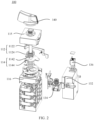
- the embodiments provide a rotary switch 100, including an operating mechanism 110, an on-off apparatus 120, and a tripping component 130, and the operating mechanism 110 includes an energy storage component 112 and a drive component 114.
- the drive component 114 is separately in driving connection with the energy storage component 112 and the on-off apparatus 120.
- the energy storage component 112 includes a latch 1122 and an energy storage spring 1124 that cooperates with the latch 1122.
- the energy storage spring 1124 can be separately connected to the latch 1122 and the drive component 114 in a snap-fit manner, the drive component 114 is rotated, so that the energy storage component 112 can store energy, and the drive component 114 is used to drive the on-off apparatus 120 to be switched on.
- the latch 1122 cooperates with the tripping component 130, so that the latch 1122 locks or unlocks the energy storage spring 1124.
- the energy storage spring 1124 drives the drive component 114 to rotate to a switch-off position of the on-off apparatus 120.
- the operating mechanism 110 is mainly used as an actuator for manual switch-on and remote automatic switch-off.
- switch-on is required, the drive component 114 is rotated.
- the energy storage spring 1124 completes energy storage, and the on-off apparatus 120 is driven to act, to switch on the on-off apparatus 120.
- remote control switch-off is required, the tripping component 130 is made to act, by sending an electrical signal control instruction to the tripping component 130.
- the latch 1122 When the tripping component 130 acts, the latch 1122 is driven to act, so that the latch 1122 and the energy storage spring 1124 are separated in a snap-fit position, elastic potential energy accumulated by the energy storage spring 1124 is released, and in a process of releasing the elastic potential energy and restoration from elastic deformation, the drive component 114 is driven to rotate to the switch-off position of the on-off apparatus 120 to implement a switch-off operation of the on-off apparatus 120.
- the energy storage component 112 and the on-off apparatus 120 are separately connected to the drive component 114
- the energy storage component 112 includes the latch 1122 and the energy storage spring 1124 that cooperates with the latch 1122
- the energy storage spring 1124 can be separately connected to the latch 1122 and the drive component 114 in a snap-fit manner, and when the drive component 114 moves, the energy storage spring 1124 is driven to act. Since the energy storage spring 1124 can be connected to the latch 1122 in a snap-fit manner, the energy storage spring 1124 can accumulate elastic potential energy.
- the drive component 114 may drive the on-off apparatus 120 to act, to switch on the on-off apparatus 120.
- the latch 1122 cooperates with the tripping component 130.
- the latch 1122 can be driven to act, so that the latch 1122 is no longer connected to the energy storage spring 1124 in a snap-fit manner and no longer locks the energy storage spring 1124.
- the energy storage spring 1124 is connected to the drive component 114 in a snap-fit manner in a process of restoration from elastic deformation, to drive the drive component 114 to rotate to the switch-off position of the on-off apparatus 120 to implement a switch-off operation of the on-off apparatus 120.
- This process does not require a continuous power output to be provided to switch off the on-off apparatus 120. This can improve reliability of a remote switch-off action of the rotary switch 100.
- the operating mechanism 110 further includes an upper cover 115 and a mounting base 116 connected to the upper cover 115.
- the drive component 114 includes a rotating shaft 1142 and a drive part 1144 connected to the rotating shaft 1142.
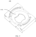
- a mounting slot 1162 is disposed in the mounting base 116.
- a rotating base 117 is disposed in the mounting slot 1162, the rotating base 117 is connected to the on-off apparatus 120, and a first elastic part 118 (shown in FIG. 7 ) is disposed in the rotating base 117.
- the rotating shaft 1142 is rotated, the rotating base 117 can be driven to rotate by using the first elastic part 118, to switch off or switch on the on-off apparatus 120.
- the rotating shaft 1142 passes through the upper cover 115 and extends to a position in which the mounting base 116 is located.
- the drive part 1144 connected to the rotating shaft 1142 is located in the position in which the mounting base 116 is located.
- the drive part 1144 is used to drive the first elastic part 118 to be elastically deformed, and an elastic force for the first elastic part 118 to restore from elastic deformation causes the rotating base 117 to rotate, to drive the on-off apparatus 120 to switch off or switch on. Because the rotating base 117 rotates in the mounting slot 1162, an outer ring of the rotating base 117 and an inner ring of the mounting slot 1162 are circular, to facilitate relative rotation.
- the embodiments do not impose a specific limitation on the first elastic part 118, provided that a required driving force for switching off or switching on the on-off apparatus 120 can be provided.
- the first elastic part 118 may be an elastic part such as a torsion spring or a clockwork spring, in a process in which when the rotating shaft 1142 is rotated so that the energy storage spring 1124 stores energy, the first elastic part 118 is driven to elastically deform, and the first elastic part 118 drives the rotating base 117 to rotate, to switch on the on-off apparatus 120. In a process of releasing the energy of the energy storage spring 1124, the first elastic part 118 is also restored from elastic deformation to perform work, and drives the rotating base 117 to rotate back, to switch off the on-off apparatus 120.
- a first push part 1144a and a second push part 1144b are disposed on the drive part 1144.
- the rotating base 117 includes a rotating base body 1172, and a first pawl 1174 and a second pawl 1176 disposed on the rotating base body 1172.
- the first pawl 1174 and the second pawl 1176 are disposed opposite to each other, and there is a preset space 1177 between an end face of the first pawl 1174 and an end face of the second pawl 1176.
- a first locking protrusion 1152 and a second locking protrusion 1154 are disposed on the upper cover 115 at a corresponding interval, and both the first locking protrusion 1152 and the second locking protrusion 1154 can be clamped in the preset space 1177.
- the first push part 1144a is capable of abutting against the first pawl 1174, so that the first pawl 1174 retracts towards the first gap 1178, to be released from locking of the first locking protrusion 1152.
- the second push part 1144b is capable of abutting against the second pawl 1176, so that the second pawl 1176 retracts towards the second gap 1179, to be released from locking of the second locking protrusion 1154.
- the drive part 1144 is rotated synchronously with the rotating shaft 1142.
- the first push part 1144a moves towards the first pawl 1174.
- the first push part 1144a abuts against the first pawl 1174 (as shown in FIG. 10 ), and continues to push the first pawl 1174 forward until the first push part 1144a presses the first pawl 1174 to deform towards the first gap 1178 (as shown in FIG. 11 ).
- the end face of the first pawl 1174 is misaligned with the first locking protrusion 1152, so that the rotating base 117 can be continuously rotated, to switch on the on-off apparatus 120.
- the preset space 1177 between the end face of the first pawl 1174 and the end face of the second pawl 1176 corresponds to the second locking protrusion 1154 to lock the rotating base 117 to prevent an unexpected action of the on-off apparatus 120. This helps to ensure stability of a state of the on-off apparatus 120.
- the tripping component 130 acts to make the latch 1122 unlock the energy storage spring 1124.
- elastic potential energy accumulated by the energy storage spring 1124 is released to drive the rotating shaft 1142 to rotate back.
- the drive part 1144 is rotated synchronously with the rotating shaft 1142, and the second push part 1144b moves towards the second pawl 1176.
- the second push part 1144b abuts against the second pawl 1176, and continues to push the second pawl 1176 forward until the second push part 1144b presses the second pawl 1176 to deform towards the second gap 1179.
- the end face of the second pawl 1176 is misaligned with the second locking protrusion 1154, so that the rotating base 117 can be continuously rotated, to switch off the on-off apparatus 120.
- the preset space 1177 between the end face of the first pawl 1174 and the end face of the second pawl 1176 corresponds to the first locking protrusion 1152, so that rotation of the rotating base 117 can be driven only by the operating mechanism 110 to prevent an unexpected action of the on-off apparatus 120. This helps to ensure stability of a state of the on-off apparatus 120.
- a first protrusion 1144c facing the rotating base 117 is further disposed on the drive part 1144, a stopper 1171 is further disposed in the rotating base 117, and in an optional embodiment of this application, the first elastic part 118 includes an elastic body 1182, and a first end part 1184 and a second end part 1186 separately connected to the elastic body 1182.
- the first end part 1184 abuts against the first protrusion 1144c, and the second end part 1186 abuts against the stopper 1171.
- the drive part 1144 is rotated, so that the first elastic part 118 is elastically deformed.
- the first push part 1144a abuts against the first pawl 1174, and continues to push the first pawl 1174 forward until the first push part 1144a presses the first pawl 1174 to deform towards the first gap 1178, so that the first pawl 1174 passes the first locking protrusion 1152.
- the first locking protrusion 1152 After the first pawl 1174 passes the first locking protrusion 1152, the first locking protrusion 1152 no longer plays a locking role on the rotating base 117, and the first elastic part 118 drives the rotating base 117 to switch on the on-off apparatus 120 through the stopper 1171.
- elastic potential energy accumulated by the energy storage spring 1124 is released to drive the rotating shaft 1142 to rotate back.
- the drive part 1144 is rotated synchronously with the rotating shaft 1142.
- the second push part 1144b abuts against the second pawl 1176, and continues to push the second pawl 1176 forward until the second push part 1144b presses the second pawl 1176 to deform towards the second gap 1179.
- the end face of the second pawl 1176 is misaligned with the second locking protrusion 1154, and the first elastic part 118 drives the rotating base 117 to rotate back by using the stopper 1171, to switch off the on-off apparatus 120.
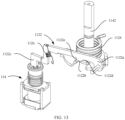
- the energy storage spring 1124 is disposed on the rotating shaft 1142, the energy storage spring 1124 includes an energy storage spring body 1124a, and a first torsion arm 1124b and a second torsion arm 1124c separately connected to the energy storage spring body 1124a, and a second protrusion 1144d away from the rotating base 117 is further disposed on the drive part 1144.
- the first torsion arm 1124b is connected to the upper cover 115 in a snap-fit manner, and the second torsion arm 1124c abuts against the second protrusion 1144d.
- the latch 1122 includes a hinged part 1122a hinged with the upper cover 115, a locking part 1122b for locking the second torsion arm 1124c, and a tripping part 1122c that cooperates with the tripping component 130.
- the latch 1122 cooperates with the tripping component 130 by using the tripping part 1122c.
- the second protrusion 1144d of the drive part 1144 drives the second torsion arm 1124c of the energy storage spring 1124 to move synchronously with the drive part 1144, and the first torsion arm 1124b of the energy storage spring 1124 is connected to the upper cover 115 in a snap-fit manner, so that the energy storage spring 1124 is elastically deformed in a movement process of the drive part 1144, thereby generating elastic potential energy and switching on the on-off apparatus 120 at the same time.
- the second protrusion 1144d of the drive part 1144 drives the second torsion arm 1124c of the energy storage spring 1124 to move synchronously with the drive part 1144, the second torsion arm 1124c of the energy storage spring 1124 is clamped to the locking part 1122b, so that elastic potential energy generated by the energy storage spring 1124 is maintained.
- the rotating shaft 1142 may be rotated back and forth to switch off or switch on the rotary switch 100.
- the tripping component 130 is configured to receive a control signal, and act based on the control signal, for example, exerting a force on the tripping part 1122c to move the tripping part 1122c away from a position in which the tripping component 130 is located.
- the hinged part 1122a of the latch 1122 and the upper cover 115 are rotated relative to each other, so that the locking part 1122b of the latch 1122 moves.
- the second torsion arm 1124c of the energy storage spring 1124 is no longer limited, and the energy storage spring 1124 can be restored from elastic deformation, to drive the drive part 1144 to rotate, so that the drive part 1144 is rotated to a switch-off position, thereby completing a switch-off operation of the on-off apparatus 120.
- a guide face 1122d is disposed between the hinged part 1122a and the locking part 1122b, and a locking face 1122e is disposed on a side, of the locking part 1122b, away from the guide face 1122d.
- the rotating shaft 1142 drives the drive part 1144 to rotate
- the second protrusion 1144d on the drive part 1144 drives the second torsion arm 1124c to rotate following the drive part 1144.
- the second torsion arm 1124c moves, the second torsion arm 1124c abuts against the guide face 1122d, and moves along the guide face 1122d to a position in which the locking part 1122b is located.
- the second torsion arm 1124c moves to a side, of the locking part 1122b, away from the guide face 1122d, that is, when the second torsion arm 1124c moves to a side, of the locking part 1122b, provided with the locking face 1122e, the second torsion arm 1124c is locked by the locking part 1122b. Even if the drive part 1144 no longer exerts a force on the second torsion arm 1124c, the second torsion arm 1124c cannot be restored to an initial state, so that an energy storage operation is performed on the energy storage spring 1124.
- the tripping component 130 When the tripping component 130 receives a tripping signal, the tripping component 130 acts to move the tripping part 1122c away from the position in which the tripping component 130 is located. In a movement process of the tripping part 1122c, a locking amount of the locking face 1122e for the second torsion arm 1124c of the energy storage spring 1124 is gradually reduced until the second torsion arm 1124c is released from a locking action of the locking part 1122b.
- the elastic potential energy accumulated by the energy storage spring 1124 is released, and the second protrusion 1144d is used to drive the drive part 1144 to rotate to a switch-off position, so that the on-off apparatus 120 is switched off.
- the tripping component 130 includes a housing 132 and a trip unit 134 disposed in the housing 132, the housing 132 is connected to the operating mechanism 110, and a reset button 136 is further disposed on the housing 132, to reset the trip unit 134 after the latch 1122 unlocks the energy storage spring 1124.
- the trip unit 134 may be any one of a magnetic flux converter, a shunt trip unit, an undervoltage trip unit, and an overvoltage trip unit.
- An action of the trip unit 134 is controlled by an electrical signal, so that the latch 1122 releases limit on the energy storage spring 1124, so that the rotary switch 100 responds quickly and implements a remote switch-off function.
- the trip unit 134 needs to be reset manually to facilitate a next action.
- the reset button 136 is used to make a reset operation of the trip unit 134 easier without using other auxiliary tools.
- the energy storage component 112 further includes a second elastic part 1126, and the second elastic part 1126 is connected to the latch 1122, so that the latch 1122 locks the energy storage spring 1124.
- the second elastic part 1126 is disposed between the latch 1122 and the upper cover 115, or the second elastic part 1126 is disposed between the latch 1122 and the mounting base 116.
- the second elastic part 1126 may be in a form of a compression spring or an elastic sheet, so that there is a repulsive force between the latch 1122 and the upper cover 115, and the tripping part 1122c tends to move towards the trip unit 134.
- the second elastic part 1126 When the second elastic part 1126 is disposed between the latch 1122 and the mounting base 116, the second elastic part 1126 may be in a form of a tension spring or an elastic rope, so that the tripping part 1122c tends to move towards the trip unit 134, to ensure that the locking part 1122b can stably lock the second torsion arm 1124c of the energy storage spring 1124.
- the on-off apparatus 120 includes a mounting housing 128, and a moving contact component 122, a fixed contact component 124, and a shaft coupler 126 disposed in the mounting housing 128.
- the moving contact component 122 is connected to the rotating base 117 through the shaft coupler 126, so that the rotating base 117 drives the moving contact component 122 to be in contact with or separate from the fixed contact component 124.
- a connection hole 1173 is correspondingly disposed on the rotating base 117, so that the shaft coupler 126 is connected to the rotating base 117, and the moving contact component 122 is also connected to the shaft coupler 126, so that the moving contact component 122 and the rotating base 117 are rotated synchronously.
- Connected conductors are disposed on the moving contact component 122, and there are two fixed contact components 124. Also, a conductor is disposed on each fixed contact component 124.
- the moving contact component 122 is rotated, so that the conductors on the moving contact component 122 are respectively connected to the conductors on the two fixed contacts to form a connected circuit. When the moving contact is rotated to another position, the conductors on the two fixed contact components 124 are disconnected to form an open circuit.
- a sealing ring is disposed on the rotating shaft 1142, and the sealing ring is located between the rotating shaft 1142 and the upper cover 115.
- a knob 140 is further disposed on the rotating shaft 1142, and the knob 140 is located on an end, of the rotating shaft 1142, away from the drive part 1144.
- a ring slot 1142a is disposed on the rotating shaft 1142, and the sealing ring is disposed on the outer ring of the ring slot 1142a, so that a position of the sealing ring and a position of the rotating shaft 1142 are relatively fixed.
- the sealing ring can play a seal role to enhance sealing performance of the rotary switch 100.
- the knob 140 disposed on the rotating shaft 1142 is used to make it more labor-saving when the rotary switch 100 is manually operated, which is convenient for operation.
Landscapes
- Breakers (AREA)
- Driving Mechanisms And Operating Circuits Of Arc-Extinguishing High-Tension Switches (AREA)
Priority Applications (1)
| Application Number | Priority Date | Filing Date | Title |
|---|---|---|---|
| EP25220723.8A EP4726761A2 (de) | 2020-07-20 | 2021-06-15 | Drehschalter |
Applications Claiming Priority (2)
| Application Number | Priority Date | Filing Date | Title |
|---|---|---|---|
| CN202010703233.3A CN113963978B (zh) | 2020-07-20 | 2020-07-20 | 一种旋转开关 |
| PCT/CN2021/100161 WO2022017076A1 (zh) | 2020-07-20 | 2021-06-15 | 一种旋转开关 |
Related Child Applications (2)
| Application Number | Title | Priority Date | Filing Date |
|---|---|---|---|
| EP25220723.8A Division EP4726761A2 (de) | 2020-07-20 | 2021-06-15 | Drehschalter |
| EP25220723.8A Division-Into EP4726761A2 (de) | 2020-07-20 | 2021-06-15 | Drehschalter |
Publications (4)
| Publication Number | Publication Date |
|---|---|
| EP4174893A1 true EP4174893A1 (de) | 2023-05-03 |
| EP4174893A4 EP4174893A4 (de) | 2024-01-10 |
| EP4174893B1 EP4174893B1 (de) | 2026-01-28 |
| EP4174893C0 EP4174893C0 (de) | 2026-01-28 |
Family
ID=79459944
Family Applications (2)
| Application Number | Title | Priority Date | Filing Date |
|---|---|---|---|
| EP21845663.0A Active EP4174893B1 (de) | 2020-07-20 | 2021-06-15 | Drehschalter |
| EP25220723.8A Pending EP4726761A2 (de) | 2020-07-20 | 2021-06-15 | Drehschalter |
Family Applications After (1)
| Application Number | Title | Priority Date | Filing Date |
|---|---|---|---|
| EP25220723.8A Pending EP4726761A2 (de) | 2020-07-20 | 2021-06-15 | Drehschalter |
Country Status (4)
| Country | Link |
|---|---|
| US (1) | US12315687B2 (de) |
| EP (2) | EP4174893B1 (de) |
| CN (1) | CN113963978B (de) |
| WO (1) | WO2022017076A1 (de) |
Families Citing this family (10)
| Publication number | Priority date | Publication date | Assignee | Title |
|---|---|---|---|---|
| CN112216567A (zh) * | 2020-10-30 | 2021-01-12 | 上海良信电器股份有限公司 | 旋转开关的操作装置及旋转开关 |
| USD1014443S1 (en) * | 2021-05-04 | 2024-02-13 | Schneider Electric Industries Sas | Part of a circuit breaker |
| CN116564746A (zh) * | 2022-01-27 | 2023-08-08 | 天津首瑞智能电气有限公司 | 一种隔离开关的搭接和脱离机构、操作机构及隔离开关 |
| CN117238702A (zh) * | 2022-06-06 | 2023-12-15 | 德力西电气有限公司 | 旋转开关及操作机构 |
| US12469657B2 (en) * | 2022-08-12 | 2025-11-11 | Ningbo Lingyue Intelligent Equipment Co., Ltd | Switch handle assembly and cutter control system containing same |
| CN117711850A (zh) * | 2022-09-07 | 2024-03-15 | 上海正泰智能科技有限公司 | 远程控制旋转隔离开关 |
| CN115410877B (zh) * | 2022-11-03 | 2023-03-24 | 东莞市中汇瑞德电子股份有限公司 | 开关装置和供电设备 |
| CN116631794B (zh) * | 2023-06-08 | 2025-09-23 | 上海思源低压开关有限公司 | 一种隔离开关的驱动转矩传递装置 |
| CN119446806A (zh) * | 2023-07-31 | 2025-02-14 | 施耐德电气(中国)有限公司 | 用于开关设备的双向操作机构及开关设备组件 |
| CN119542058A (zh) * | 2023-08-31 | 2025-02-28 | 上海良信电器股份有限公司 | 一种复位机构、转换开关及配电设备 |
Family Cites Families (23)
| Publication number | Priority date | Publication date | Assignee | Title |
|---|---|---|---|---|
| FR2517114A1 (fr) * | 1981-11-26 | 1983-05-27 | Alsthom Cgee | Commutateur electrique a commande rotative rappele automatiquement en l'absence de tension |
| DE102005037437B4 (de) * | 2005-08-09 | 2007-12-27 | Moeller Gmbh | Elektrischer Schutzschalter mit Schutzfunktion |
| CN200959299Y (zh) * | 2006-05-09 | 2007-10-10 | 黄冠雄 | 燃气炉具电子定时自动关闭开关 |
| CN201117519Y (zh) * | 2007-08-13 | 2008-09-17 | 崧腾企业股份有限公司 | 改良型旋转开关 |
| US7920037B2 (en) * | 2008-05-08 | 2011-04-05 | Cooper Technologies Company | Fault interrupter and load break switch |
| US20090277768A1 (en) * | 2008-05-08 | 2009-11-12 | Cooper Technologies Company | Low Oil Trip Assembly for a Fault Interrupter and Load Break Switch |
| CN101604601B (zh) * | 2009-06-05 | 2012-10-03 | 上海诺雅克电气有限公司 | 具有气压致动脱扣功能的快速跳闸断路器 |
| CN101923992B (zh) * | 2010-08-20 | 2012-12-12 | 上海电科电器科技有限公司 | 一种控制与保护开关电器操作机构 |
| CN204029742U (zh) * | 2014-07-16 | 2014-12-17 | 浙江天正电气股份有限公司 | 带远程控制的自动分闸机构及应用该分闸机构的断路器 |
| US9964189B2 (en) * | 2016-01-27 | 2018-05-08 | Schweitzer Engineering Laboratories, Inc. | Rotary actuation device |
| CN107045958B (zh) | 2016-02-05 | 2019-04-23 | 上海良信电器股份有限公司 | 一种旋转式开关的操作机构 |
| CN106057545B (zh) * | 2016-06-23 | 2018-06-01 | 常熟开关制造有限公司(原常熟开关厂) | 旋转开关操作机构 |
| CN108878224A (zh) | 2017-05-09 | 2018-11-23 | 人民电器集团上海有限公司 | 一种带隔离断路器 |
| CN108648970B (zh) * | 2018-07-02 | 2024-04-26 | 亚洲电力设备(深圳)有限公司 | 一种断路器的脱扣机构 |
| CN209401499U (zh) * | 2018-09-18 | 2019-09-17 | 上海良信电器股份有限公司 | 一种改良的旋转开关操作机构 |
| CN110911187B (zh) | 2018-09-18 | 2024-07-16 | 上海良信电器股份有限公司 | 一种旋转式开关操作机构 |
| CN110911186B (zh) * | 2018-09-18 | 2024-10-22 | 上海良信电器股份有限公司 | 一种改良的旋转开关操作机构 |
| CN112750643B (zh) * | 2019-10-31 | 2025-03-18 | 上海良信电器股份有限公司 | 一种具有远程控制切换功能的旋转开关 |
| CN211376497U (zh) * | 2019-10-31 | 2020-08-28 | 上海良信电器股份有限公司 | 一种具有远程控制切换功能的旋转开关 |
| CN210607020U (zh) * | 2019-12-02 | 2020-05-22 | 浙江思创电力科技股份有限公司 | 一种带防误合闸装置的断路器 |
| CN113963979B (zh) * | 2020-07-20 | 2023-01-10 | 上海良信电器股份有限公司 | 一种远程分闸机构及旋转开关 |
| CN111863496A (zh) * | 2020-07-20 | 2020-10-30 | 上海良信电器股份有限公司 | 一种储能状态监测结构及旋转开关 |
| CN114093732B (zh) * | 2021-10-18 | 2024-06-25 | 华为数字能源技术有限公司 | 开关、功率变换装置和供电系统 |
-
2020
- 2020-07-20 CN CN202010703233.3A patent/CN113963978B/zh active Active
-
2021
- 2021-06-15 EP EP21845663.0A patent/EP4174893B1/de active Active
- 2021-06-15 WO PCT/CN2021/100161 patent/WO2022017076A1/zh not_active Ceased
- 2021-06-15 EP EP25220723.8A patent/EP4726761A2/de active Pending
-
2023
- 2023-01-20 US US18/157,672 patent/US12315687B2/en active Active
Also Published As
| Publication number | Publication date |
|---|---|
| CN113963978B (zh) | 2023-01-10 |
| US20230154702A1 (en) | 2023-05-18 |
| EP4174893A4 (de) | 2024-01-10 |
| EP4726761A2 (de) | 2026-04-15 |
| EP4174893B1 (de) | 2026-01-28 |
| CN113963978A (zh) | 2022-01-21 |
| EP4174893C0 (de) | 2026-01-28 |
| US12315687B2 (en) | 2025-05-27 |
| WO2022017076A1 (zh) | 2022-01-27 |
Similar Documents
| Publication | Publication Date | Title |
|---|---|---|
| EP4174893B1 (de) | Drehschalter | |
| US12500051B2 (en) | Energy storage status monitoring structure and rotary switch | |
| CN205531813U (zh) | 一种电子挂锁 | |
| CN212365820U (zh) | 一种储能状态监测结构及旋转开关 | |
| US12300447B2 (en) | Remote switch-off mechanism and rotary switch | |
| EP1487002A2 (de) | Elektrische Fernbedienung | |
| KR20050003982A (ko) | 회로 차단기의 외부조작 핸들장치 | |
| CN113257595B (zh) | 一种应用于双电源自动转换开关的切换机构 | |
| CN1881495B (zh) | 带有可转动锁定装置的电开关设备的致动器 | |
| CN115101388B (zh) | 一种具有机械锁的断路器附件及断路器 | |
| CN112151336B (zh) | 一种操作机构及断路器 | |
| CN213401058U (zh) | 断路器的控制电路及断路器 | |
| CN119446806A (zh) | 用于开关设备的双向操作机构及开关设备组件 | |
| CN109545630B (zh) | 一种断路器附件的操作机构、断路器附件及组合式断路器 | |
| CN113871246A (zh) | 一种储能脱扣装置和旋转开关 | |
| CN220456330U (zh) | 一种脱扣机构及断路器 | |
| CN113327824A (zh) | 剩余电流动作断路器操作机构和剩余电流动作断路器 | |
| CN222581069U (zh) | 一种漏电断路器的漏电故障指示机构 | |
| CN215299128U (zh) | 带有分闸结构的断路器 | |
| CN212725073U (zh) | 一种双电源开关的执行机构 | |
| JP2672632B2 (ja) | 回路しや断器の電動操作装置 | |
| CN211376563U (zh) | 剩余电流动作断路器操作机构和剩余电流动作断路器 | |
| CN210182251U (zh) | 操作手柄 | |
| CN121862632A (zh) | 操作机构及隔离开关 | |
| CN121709490A (zh) | 组合操作手柄、操作机构及断路器 |
Legal Events
| Date | Code | Title | Description |
|---|---|---|---|
| STAA | Information on the status of an ep patent application or granted ep patent |
Free format text: STATUS: THE INTERNATIONAL PUBLICATION HAS BEEN MADE |
|
| PUAI | Public reference made under article 153(3) epc to a published international application that has entered the european phase |
Free format text: ORIGINAL CODE: 0009012 |
|
| STAA | Information on the status of an ep patent application or granted ep patent |
Free format text: STATUS: REQUEST FOR EXAMINATION WAS MADE |
|
| 17P | Request for examination filed |
Effective date: 20230125 |
|
| AK | Designated contracting states |
Kind code of ref document: A1 Designated state(s): AL AT BE BG CH CY CZ DE DK EE ES FI FR GB GR HR HU IE IS IT LI LT LU LV MC MK MT NL NO PL PT RO RS SE SI SK SM TR |
|
| DAV | Request for validation of the european patent (deleted) | ||
| DAX | Request for extension of the european patent (deleted) | ||
| A4 | Supplementary search report drawn up and despatched |
Effective date: 20231212 |
|
| RIC1 | Information provided on ipc code assigned before grant |
Ipc: H01H 71/12 20060101ALI20231206BHEP Ipc: H01H 71/10 20060101ALI20231206BHEP Ipc: H01H 19/02 20060101ALI20231206BHEP Ipc: H01H 19/10 20060101AFI20231206BHEP |
|
| STAA | Information on the status of an ep patent application or granted ep patent |
Free format text: STATUS: EXAMINATION IS IN PROGRESS |
|
| 17Q | First examination report despatched |
Effective date: 20250317 |
|
| GRAP | Despatch of communication of intention to grant a patent |
Free format text: ORIGINAL CODE: EPIDOSNIGR1 |
|
| STAA | Information on the status of an ep patent application or granted ep patent |
Free format text: STATUS: GRANT OF PATENT IS INTENDED |
|
| INTG | Intention to grant announced |
Effective date: 20250918 |
|
| GRAS | Grant fee paid |
Free format text: ORIGINAL CODE: EPIDOSNIGR3 |
|
| GRAA | (expected) grant |
Free format text: ORIGINAL CODE: 0009210 |
|
| STAA | Information on the status of an ep patent application or granted ep patent |
Free format text: STATUS: THE PATENT HAS BEEN GRANTED |
|
| AK | Designated contracting states |
Kind code of ref document: B1 Designated state(s): AL AT BE BG CH CY CZ DE DK EE ES FI FR GB GR HR HU IE IS IT LI LT LU LV MC MK MT NL NO PL PT RO RS SE SI SK SM TR |
|
| REG | Reference to a national code |
Ref country code: CH Ref legal event code: F10 Free format text: ST27 STATUS EVENT CODE: U-0-0-F10-F00 (AS PROVIDED BY THE NATIONAL OFFICE) Effective date: 20260128 Ref country code: GB Ref legal event code: FG4D |
|
| REG | Reference to a national code |
Ref country code: IE Ref legal event code: FG4D |
|
| U01 | Request for unitary effect filed |
Effective date: 20260128 |
|
| U07 | Unitary effect registered |
Designated state(s): AT BE BG DE DK EE FI FR IT LT LU LV MT NL PT RO SE SI Effective date: 20260203 |